1900 MITSUBISHI DIAMANTE battery location
[x] Cancel search: battery locationPage 151 of 408
.
4-8 DRIVEABILITYAND EMISSIONS CONTROLS
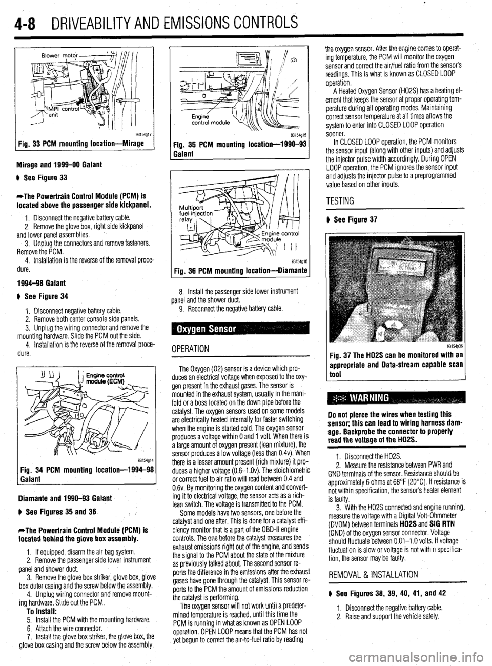
93154g17 Fig. 33 PCM mounting location-Mirage
Mirage and 1999-00 Galant
) See Figure 33
*The Powertrain Control Module (PCM) is
located above the passenger side kickpanel.
1. Disconnect the negative battery cable.
2. Remove the @love box, right side kickpanel
and lower panel assemblies.
3. Unplug the connectors and remove fasteners.
Remove the PCM.
4. Installation is the reverse of the removal proce-
dure.
1994-98 Galant
+ See Figure 34
1, Disconnect negative battery cable.
2. Remove both center console side panels.
3. Unplug the wiring connector and remove the
mounting hardware. Slide the PCM out the side.
4. installation is the reverse of the removal proce-
dure.
Diamante and 1990-93 Galant
) See Figures 35 and 38
*The Powertrain Control Module (PCM) is
located behind the glove box assembly.
1, If equipped, disarm the air bag system
2. Remove the passenger side lower instrument
panel and shower duct.
3. Remove the glove box striker, glove box, glove
box outer casing and the screw below the assembly.
4. Unplug wiring connector and remove mount-
ing hardware. Slide out the PCM.
To install: 5. Install the PCM with the mounting hardware.
6. Attach the wire connector.
7. Install the glove box striker, the glove box, the
glove box casing and the screw below the assembly.
Q3154g15 Fig. 35 PCM mounting location-1990-93
Galant
93154g16 Fig. 38 PCM mounting location-Diamante
8. Install the passenger side lower instrument
panel and the shower duct.
9. Reconnect the negative battery cable
OPERATION
The Oxygen (02) sensor is a device which pro-
duces an electrical voltage when exposed to the oxy-
gen present in the exhaust gases. The sensor is
mounted in the exhaust system, usually in the mani-
fold or a boss located on the down pipe before the
catalyst. The oxygen sensors used on some models
are electrically heated internally for faster switching
when the engine is started cold. The oxygen sensor
produces a voltage within 0 and 1 volt. When there is
a large amount of oxygen present (lean mixture), the
sensor produces a low voltage (less than 0.4~). When
there is a lesser amount present (rich mixture) it pro-
duces a higher voltage (0.6-I .Ov). The stoichiometric
or correct fuel to air ratio will read between 0.4 and
0.6~. By monitoring the oxygen content and convert-
ing it to electrical voltage, the sensor acts as a rich-
lean switch. The voltage is transmitted to the PCM.
Some models have two sensors, one before the
catalyst and one after. This is done for a catalyst eff i-
ciency monitor that is a part of the OBD-II engine
controls. The one before the catalyst measures the
exhaust emissions right out of the engine, and sends
the signal to the PCM about the state of the mixture
as previously talked about. The second sensor re-
ports the difference in the emissions after the exhaust
gases have gone through the catalyst. This sensor re-
ports to the PCM the amount of emissions reduction
the catalyst is performing.
The oxygen sensor will not work until a predeter-
mined temperature is reached, until this time the
PCM is running in what as known as OPEN LOOP
operation. OPEN LOOP means that the PCM has not
yet begun to correct the air-to-fuel ratio by reading the oxygen sensor. After the engine comes to operat-
ing temperature, the PCM will monitor the oxygen
sensor and correct the air/fuel ratio from the sensor’s
readings. This is what is known as CLOSED LOOP
operation.
A Heated Oxygen Sensor (H02S) has a heating el-
ement that keeps the sensor at proper operatmg tem-
perature during all operating modes. Maintaining
correct sensor temperature at all times allows the
system to enter into CLOSED LOOP operation
sooner.
In CLOSED LOOP operation, the PCM monitors
the sensor input (along with other inputs) and adjusts
the injector pulse width accordingly. During OPEN
LOOP operation, the PCM ignores the sensor input
and adjusts the injector pulse to a preprogrammed
value based on other inputs.
TESTING
# See Figure 37
93154p36 Fig. 37 The HD2S can be monitored with an
appropriate and Data-stream capable scan
tool
Do not pierce the wires when testing this
sensor; this can lead to wiring harness dam-
age. Backprobe the connector to properly
read the voltage of the HD2S.
1. Disconnect the H02S.
2. Measure the resistance between PWR and
GND terminals of the sensor. Resistance should be
approximately 6 ohms at 68°F (20°C) If resistance is
not within specification, the sensor’s heater element
is faulty.
3. With the H02S connected and engine running,
measure the voltage with a Digital Volt-Ohmmeter
(DVOM) between terminals
HD2S and SIG RTN (GND) of the oxygen sensor connector. Voltage
should fluctuate between 0.01-l .O volts. If voltage
fluctuation is slow or voltage is not within specifica-
tion, the sensor may be faulty.
REMOVAL &INSTALLATION
) See Figures 38, 39, 40, 41, and 42
1. Disconnect the negative battery cable
2. Raise and support the vehicle safely.
Page 192 of 408
FUEL SYSTEM 5-5,
21. Connect the negative battery cable. Refill the
cooling system.
REMOVAL & INSTALLATION
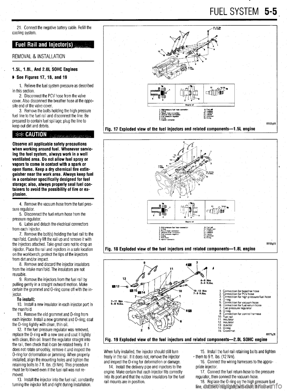
1.5L, 1.8L, And 2.OL SOHC Engines
ti See Figures 17, 18, and 19
1. Relieve the fuel system pressure as described
in this section.
2. Disconnect the PCV hose from the valve
cover. Also disconnect the breather hose at the oppo-
site end of the valve cover.
3. Remove the bolts holding the high pressure
fuel line to the fuel rail and disconnect the line. Be
prepared to contain fuel spillage; plug the line to
keep out dirt and debris.
Observe all applicable safety precautions
when working around fuel. Whenever servic-
ing the fuel system, always work in a well
ventilated area. 00 not allow fuel spray or
vapors to come in contact with a spark or
open flame. Keep a dry chemical fire extin-
guisher near the work area. Always keep fuel
in a container specifically designed for fuel
storage; also, always properly seal fuel con-
tainers to avoid the possibility of fire or ex-
plosion.
4. Remove the vacuum hose from the fuel pres-
sure regulator.
5. Disconnect the fuel return hose from the
pressure regulator.
6. Label and detach the electrical connectors
from each injector.
7. Remove the bolt(s) holding the fuel rail to the
manifold. Carefully lift the rail up and remove it with
the injectors attached. Take great care not to drop an
injector Place the rail and Injectors in a safe location
on the workbench; protect the tips of the injectors
from dirt and/or Impact.
8. Remove and discard the injector rnsulators
from the intake manifold. The insulators are not
reusable.
9. Remove the injectors from the fuel rail by
pulling gently in a straight outward motion. Make
certain the grommet and O-ring come off with the in-
jector.
To install: 10. Install a new insulator in each injector port in
the manifold.
11. Remove the old grommet and O-ring from
each injector Install a new grommet and O-ring; coat
the O-ring lightly with clean, thin oil.
12. If the fuel pressure regulator was removed,
replace the O-ring with a new one and coat it lightly
with clean, thin oil Insert the regulator straight into
the rail, then check that it can be rotated freely. If It
does not rotate smoothly, remove it and inspect the
O-ring for deformation or jamming. When properly
installed, align the mounting holes and tighten the
retaining bolts to 7 ft. Ibs. (9 Nm). This procedure
must be followed even if the fuel rail was not re-
moved.
13. Install the injector into the fuel rail, constantly
turning the injector left and right during installation.
1Hilt4naunfu(norc e Fu(l
:E%!,,.,.- 1: IEE
: Efgz tz!z? :: %%I
;P&.xmeaw 13 m
Fig. 17 Exploded view of the fuel injectors and related components-l .5L engine
I
.xs.
1 Connection for breather hose
2 Connection for PCV hose
3 Connection for high tm?ss”re fuel hose
4 0-ring
5 Connection for vacuum hose
6 Connecr~on for fuel return hose
7 Fuel pressure regulator
8 0-ring
9 Connection for control harness
10 Fuel ml
11 Insulator
12 insulator
13 lnlector
14 O-ring
15 Grommet
89575026
Fig. 19 Exploded view of the fuel injectors and related components-2.01 SOHC engine
When fully installed, the injector should still turn
freely in the rail. If it does not, remove the injector
and inspect the O-ring for deformation or damage.
14. Install the delivery pipe and injectors to the
engine. Make certain that each injector fits correctly
into its port and that the rubber insulators for the fuel
rail mounts are in position. 15. Install the fuel rail retaining bolts and tighten
* them to 9 ft. Ibs. (12 Nm).
16. Connect the wiring harnesses to the appro-
priate injector.
17. Connect the fuel return hose to the pressure
regulator, then connect the vacuum hose.
18. Replace the O-ring on the high pressure fuel
line, coat the O-ring lightly with clean, thin oil and
Page 194 of 408
FUELSYSTEM 5-7
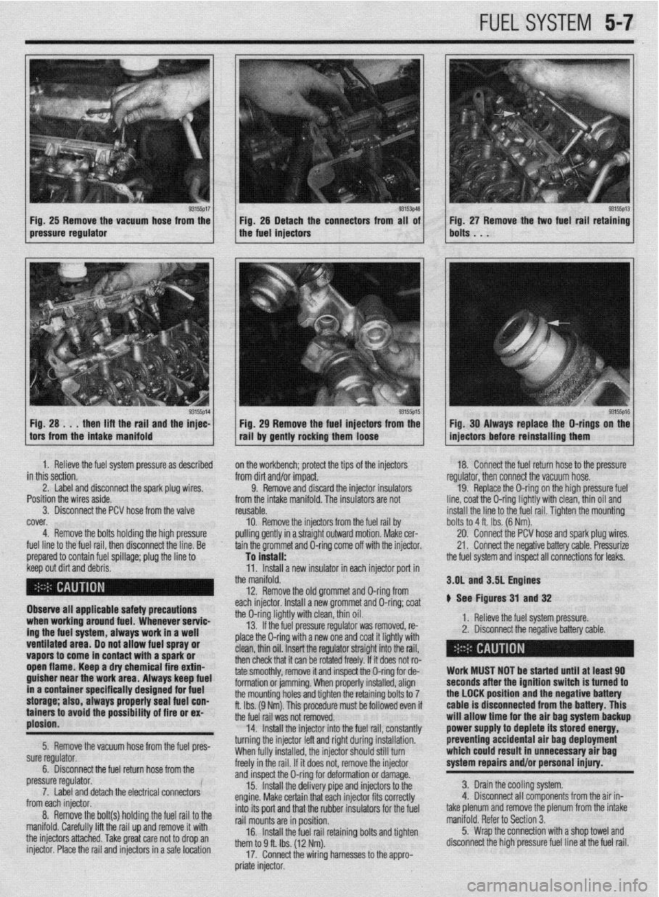
Fig, 25 Remove the vacuum hose from the Fig. 25 Detach the connectors from all of
pressure regulator the fuel injectors
1 H; :A ..;lt;;aft~rgi,i~;yl the ;F: 1 / . 93155p15 1 Fig 29 Remove the fuel injectors from the
tall by gently rocking them loose Fig. 27 Remove the two fuel rail retaining
bolts . . .
93155ps Fig. 30 Always replace the O-rings on the
injectors before reinstalling them
1. Relieve the fuel system pressure as described
in this section.
2. Label and disconnect the spark plug wires. ’
Position the wires aside.
3. Disconnect the PCV hose from the valve
cover,
4. Remove the bolts holding the high pressure
fuel line to the fuel rail, then disconnect the line. Be
prepared to contain fuel spillage; plug the line to on the workbench; protect the tips of the injectors
from dirt and/or impact.
9. Remove and discard the injector insulators
from the intake manifold. The insulators are not
reusable.
10. Remove the injectors from
pulling gently in a straight outwarc the fuel rail by
I motion. Make cer-
tain the grommet and O-ring come off with the injector. 18. Connect the fuel return hose to the pressure
regulator, then connect the vacuum hose.
19. Replace the O-ring on the high pressure fuel
line, coat the O-ring lightly with clean, thin oil and
install the line to the fuel rail. Tiahten the mountina
To install: -
the fuel system and inspect all connections for leaks. bolts to 4 ft. Ibs. (6 Nm).
20. Connect the PCV hose and spark plug wires.
21. Connect the negative battery cable. Pressurize
1. neneve me rueI system pressure.
2. Disconnect the negative battery cable. 3.OL and 3.5L Engines
# See Figures 31 and 32
> - ,. .* , ,
I
I
Work MUST NOT be started until at least 90
seconds after the ignition switch is turned to
the LOCK position and the negative battery
cable is disconnected from the battery. This
will allow time for the air bag system backup
power supply to deplete its stored energy,
preventing accidental air bag deployment
which could result in unnecessary air bag
system repairs and/or personal injury.
3. Drain the cooling system.
4. Disconnect all components from the air in-
take plenum and remove the plenum from the intake
manifold. Refer to Section 3.
5. Wrap the connection with a shop towel and
disconnect the high pressure fuel line at the fuel rail. keep out dirt and debris.
Observe all applicable safety precautions
when working around fuel. Whenever servic-
ing the fuel system, always work in a well
ventilated area. Do not allow fuel spray or
vapors to come in contact with a spark or
open flame. Keep a dry chemical fire extin-
guisher near the work area. Always keep fuel
in a container specifically designed for fuel
storage; also, always properly seal fuel con-
tainers to avoid the possfbility of fire or ex-
plosion.
5. Remove the vacuum hose from the fuel pres-
sure regulator.
6. Disconnect the fuel return hose from the
pressure regulator.
7. Label and detach the electrical connectors
from each injector.
8. Remove the bolt(s) holding the fuel rail to the
manifold. Carefully lift the rail up and remove it with
the injectors attached. Take great care not to drop an
injector. Place the rail and injectors in a safe location 11. Install a new insulator in each injector port in
the manifold.
12. Remove the old grommet and D-ring from
each injector. Install a new grommet and O-ring; coat
the O-ring lightly with clean, thin oil.
13. If the fuel pressure regulator was removed, re-
place the O-ring with a new one and coat it lightly with
clean, thin oil. Insert the regulator straight into the rail,
then check that it can be rotated freely. If it does not ro-
tate smoothly, remove it and inspect the O-ring for de-
formation or jamming. When properly installed, align
the mounting holes and tighten the retaining bolts to 7
ft. Ibs. (9 Nm). This procedure must be followed even if
the fuel rail was not removed.
14. Install the injector into the fuel rail, constantly
turning the injector left and right during installation.
When fully installed, the injector should still turn
freely in the rail. If it does not, remove the injector
and inspect the O-ring for deformation or damage.
15. Install the delivery pipe and injectors to the
engine. Make certain that each injector fits correctly
into its port and that the rubber insulators for the fuel
rail mounts are in position.
16. Install the fuel rail retaining bolts and tighten
them to 9 ff. Ibs. (12 Nm).
17. Connect the wiring harnesses to the appro-
priate injector.
Page 197 of 408
5-10 FUELSYSTEM
1. _
Fuel tank pressure
-
relef vdive
REMOVAL &INSTALLATION
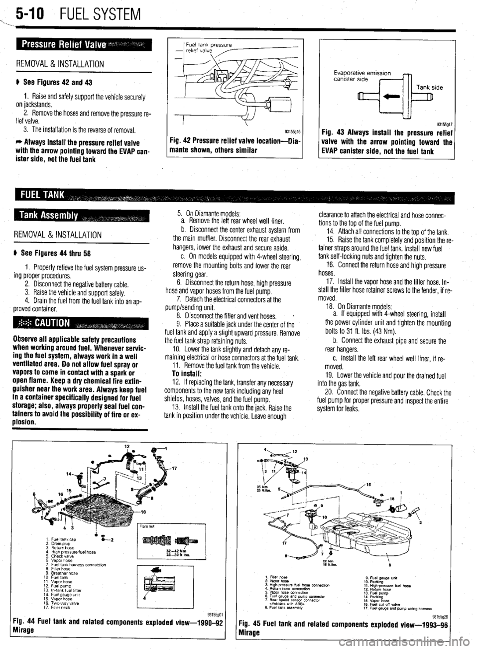
p See Figures 42 and 43
1. Raise and safely support the vehicle securely
on jackstands.
2. Remove the hoses and remove the pressure re-
lief valve.
3. The installation is the reverse of removal.
c, Always install the pressure relief valve
with the arrow pointing toward the EVAP can-
ister side, not the fuel tank 1 mame shown, others similar g3155g” Fig 42 Pressure relief valve location-llia
I I
Evaporatwe emlsslon
canister side
Tank side
+k
93155gt7 Fig. 43 Always install the pressure relief
valve with the arrow pointing toward the
EVAP canister side, not the fuel tank
REMOVAL&INSTALLATION
p See Figures 44 thru 58
1. Properly relieve the fuel system pressure us-
ing proper procedures.
2. Disconnect the negative battery cable.
3. Raise the vehicle and support safelv.
4. Drain the fuel from the fuel tank into an
ap- proved container.
Observe all applicable safety precautions
when working around fuel. Whenever servic-
ing the fuel system, always work in a well
ventilated area. Do not allow fuel spray or
vapors to come in contact with a spark or
open flame. Keep a dry chemical fire extin-
guisher near the work area. Always keep fuel
in a container specifically designed for fuel
storage; also, always properly seal fuel con-
tainers to avoid the possibility of fire or ex-
plosion.
5. On Diamante models:
a. Remove the left rear wheel well liner.
b Disconnect the center exhaust system from
the main muffler. Disconnect the rear exhaust
hangers, lower the exhaust and secure aside.
c. On models equipped with 4-wheel steering,
remove the mounting bolts and lower the rear
steering gear.
6. Disconnect the return hose, high pressure
hose and vapor hoses from the fuel pump.
7. Detach the electrical connectors at the
pump/sending unit.
8. Disconnect the filler and vent hoses.
s
9. Place a suitable jack under the center of the
fuel tank and apply a slight upward pressure. Remove
the fuel tank strap retaining nuts.
10. Lower the tank slightly and detach any re-
maining electrical or hose connectors at the fuel tank.
11. Remove the fuel tank from the vehicle.
To install: 12. If replacing the tank, transfer any necessary
components to the new tank including any heat
shields, hoses, valves, and the fuel pump.
13. Install the fuel tank onto the jack. Rarse the
tank in position under the vehicle. Leave enough
Tg. 44 Fuel tank and related components exploded view-1990-92
mirage
clearance to attach the electrical and hose connec-
tions to the top of the fuel pump.
14. Attach all connectrons to the top of the tank.
15. Raise the tank completely and position the re-
tainer straps around the fuel tank. Install new fuel
tank self-locking nuts and tighten the nuts.
16. Connect the return hose and high pressure
hoses.
17. Install the vapor hose and the filler hose. In-
stall the filler hose retainer screws to the fender, if re-
moved.
18. On Diamante models:
a. If equipped with 4-wheel steering, install
the power cylinder unit and tighten the mounting
bolts to 31 ft. Ibs. (43 Nm).
b. Connect the exhaust pipe and secure the
rear hangers.
c. Install the left rear wheel well liner, if re-
moved.
19. Lower the vehicle and pour the drained fuel
into the gas tank.
20. Connect the negative battery cable. Check the
fuel pump for proper pressure and inspect the entire
system for leaks.
:ig. 45
vlirage Fuel tank and related 93155(12E components exploded view-1993-96
Page 207 of 408
I
6-4 CHASSIS ELECTRICAL
I
printed circuit is sandwiched between two sheets of
plastic for more protection and flexibility. A complete l Weatherproof-these connectors are most the jumper wire is of too small a gauge, it
printed circuit, consisting of conductors, insulating commonly used where the connector is exposed to
may overheat and possibly melt. Never use
material and connectors for lamps or other compo- the elements. Terminals are protected against mois-
nents is called a printed circuit board. Printed cir- ture and dirt by sealing rings which provide a weath- jumpers to bypass high resistance loads in a
et-tight seal. All repairs require the use of a special circuit. Bypassing resistances, in effect, cre-
cuitry is used in place of individual wires or har- ates a short circuit. This may, in turn, cause
nesses in places where space is limited, such as terminal and the tool required to service it. Unlike
behind instrument panels. standard blade type terminals, these weatherproof damage and fire. Jumper wires should only
be used to bypass lengths of wire or to simu-
Since automotive electrical systems are very sen- terminals cannot be straightened once they are bent. late switches.
sitive to changes in resistance, the selection of prop- ‘Make certain that the connectors are properly seated
erly sized wires is critical when systems are repaired, and all of the sealing rings are in place when con-
netting leads. Jumper wires are simple, yet extremely valuable,
A loose or corroded connection or a replacement wire pieces of test equipment. They are basically test wires
that is too small for the circuit will add extra resis-
l Molded-these connectors require complete which are used to bypass sections of a circuit. Al-
replacement of the connector if found to be defective.
tance and an additional voltage drop to the circuit. though jumper wires can be purchased, they are usu-
The wire gauge number is an expression of the This means splicing a new connector assembly into ally fabricated from lengths of standard automotive
cross-section area of the conductor. Vehicles from the harness. All splices should be soldered to insure
proper contact. Use care when probing the connec- wire and whatever type of connector (alligator clip,
countries that use the metric system will typically de- spade connector or pin connector) that is required for
scribe the wire size as its cross-sectional area in tions or replacing terminals in them, as it is possible
square millimeters. In this method, the larger the to create a short circuit between opposite terminals. If the particular application being tested. In cramped,
hard-to-reach areas, it is advisable to have insulated
wire, the greater the number. Another common sys- this happens to the wrong terminal pair, it is possible
to damage certain components. Always use jumper boots over the jumper wire terminals in order to pre-
tern for expressing wire size is the American Wire vent accidental grounding. It is also advisable to in-
Gauge (AWG) system. As gauge number increases, wires between connectors for circuit checking and
NEVER probe through weatherproof seals. elude a standard automotive fuse in any jumper wire.
area decreases and the wire becomes smaller. An 18
gauge wire is smaller than a 4 gauge wire. A wire
l Hard Shell-unlike molded connectors, the This is commonly referred to as a “fused jumper”. By
inserting an in-line fuse holder between a set of test
terminal contacts in hard-shell connectors can be re-
with a higher gauge number will carry less current
placed. Replacement usually involves the use of a leads, a fused jumper wire can be used for bypassing :
than a wire with a lower gauge number. Gauge wire open circuits. Use a 5 amp fuse to provide protection
size refers to the size of the strands of the conductor, special terminal removal tool that depresses the lock- against voltage spikes.
not the size of the complete wire with insulator. It is ing tangs (barbs) on the connector terminal and al-
lows the connector to be removed from the rear of the Jumper wires are used primarily to locate open
possible, therefore, to have two wires of the same
shell. The connector shell should be replaced if it electrical circuits, on either the ground (-) side of the
gauge with different diameters because one may have
thicker insulation than the other. shows any evidence of burning, melting, cracks, or circuit or on the power (+) side. If an electrical corn-
breaks. Replace individual terminals that are burnt, ponent fails to operate, connect the jumper wire be-
It is essential to understand how a circuit works
corroded, distorted or loose. tween the component and a good ground. If the corn-
before trying to figure out why it doesn’t. An electrical ponent operates only with the jumper installed, the
schematic shows the electrical current paths when a ground circuit is open. If the ground circuit is good,
circuit is operating properly. Schematics break the but the component does not operate, the circuit be-
entire electrical system down into individual circuits. tween the power feed and component may be open. ’
In a schematic, usually no attempt is made to repre- Pinpointing the exact cause of trouble in an elec- By moving the jumper wire successively back from
trical circuit is most times accomplished by the use the component toward the power source, you can
; : sent wiring and components as they physically ap-
pear on the vehicle; switches and other components of special test equipment. The following describes isolate the area of the circuit where the open is lo-
are shown as simply as possible. Face views of har- different types of commonly used test equipment and cated. When the component stops functioning, or the f
j
ness connectors show the cavity or terminal locations briefly explains how to use them in diagnosis. In ad- power is cut off, the open is in the segment of wire j
in all multi-pin connectors to help locate test points. dition to the information covered below, the tool between the jumper and the point previously tested.
! manufacturer’s instructions booklet (provided with You can sometimes connect the jumper wire di-
the tester) should be read and clearly under.$ood be- rectly from the battery to the “hot” terminal of the I
CONNECTORS 1 fore attempting any test procedures. component, but first make sure the component uses 1
# See Figures 5 and 6 JUMPER WIRES 12 volts in operation. Some electrical components, i
such as fuel injectors or sensors, are designed to op-
Three types of connectors are commonly used in erate on about 4 to 5 volts, and running 12 volts di- j
)
automotive applications-weatherproof, molded and rectly to these components will cause damage.
hard shell.
Never use jumper wires made from a thinner TEST LIGHTS I
gauge wire than the circuit being tested. If
# See Figure 7
The test light is used to check circuits and compo-
I nents while electrical current is flowing through
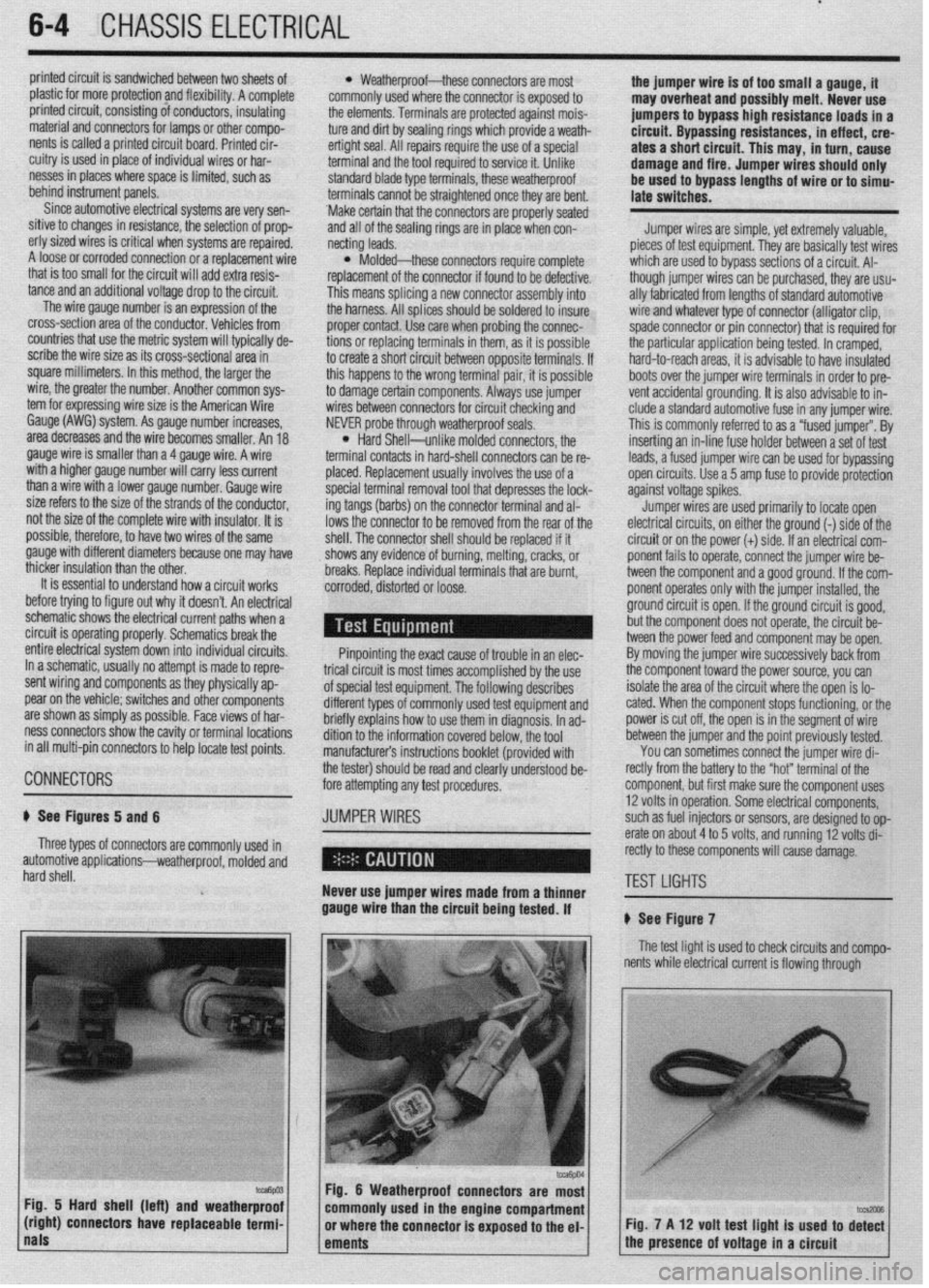
Fig. 5 Hard shell (left) and weatherproof
(right) connectors have replaceable termi- Fig. 7 A 12 volt test light is used to di%
nals
ements 1 the presence of voltage in a circuit
Page 223 of 408
.
6-20 CHASSIS ELECTRICAL
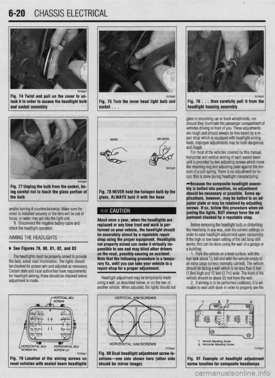
Fig. 74 Twist and pull on the cover to un-
lock it in order to access the headlight bulb
and socket assembly 93Mm Fig, 75 Turn the inner head light bulb and then carefully pull’ it from the
NO 0000 . glare in oncoming car or truck windshields, nor
should they illuminate the passenger compartment of
vehicles driving in front of you. These adjustments
are rough and should always be fine-tuned by a re-
pair shop which is equipped with headlight aiming
tools. Improper adjustments may be both dangerous
and illegal.
Fig. 77 Unplug the bulb from the socket, be-
L
ing careful not to touch the glass portion of
the bulb
I
6957Q39
Fig. 78 NEVER hold the halogen bulb by the
glass, ALWAYS hold it with the base
,
About once a year, when the headllgftts are
replaced or any time front end work is per-
formed on your vehicle, the headlight should
be accurately aimed by a reputable repair
shop uslng the proper equipment. Headlights
not properly aimed can make it virtually im-
possible to see ar Id may blind other drivers
ibly causing an accident.
Note that the’following procedure is a tempo-
rary fix, until you can take your vehicle to a
repair shop for a proper adjustment.
Headlight adjustment may be temporarily made
using a wall, as described below, or on the rear of
another vehicle. When adjusted, the lights should not For most of the vehicles covered by this manual,
horizontal and vertical aiming of eachsealed beam
unit is provided by two adjusting screws which move
the retaining ring and adjusting plate against the ten-
sion of a coil spring. There is no adjustment for fo-
cus; this is done during headlight manufacturing.
*Because the composite headlight assem-
bly is bolted into position, no adjustment
should be necessary or possible. Some ap-
plications, however, may be bolted to an ad-
juster plate or may be retained by adjusting
screws. If so, follow this procedure when ad-
@sting the lights, BUT always have the ad-
justment checked by a reputable shop.
Before removing the headlight bulb or disturbing
the headlamp in any way, note the current settings in
order to ease headlight adjustment upon reassembly.
If the high or low beam setting of the old lamp still
works, this can be done using the wall of a garage or
a building:
1. Park the vehicle on a level surface, with the
fuel tank about r/a full and with the vehicle empty of
all extra cargo (unless normally carried). The vehicle
should be facing a wall which is no less than 6 feet
(1.8m) high and 12 feet (3.7m) wide. The front of the
vehicle should be about 25 feet from the wall.
2. If aiming is to be performed outdoors, it is ad-
visable to wait until dusk in order to properly see the
% and/or turning it counterclockwise. Make sure the
cover is installed securely or the lens will be out of
focus, or water may get into the light unit.
9. Disconnect the negative battery cable and
check the headlight operation.
AIMINGTHE HEADLIGHTS
$ See Figures 79, 88, 81, 82, and 83
The headlights must be proper’ ’ ’ ’
the best, safest road illumination. ’ ’
ly armea IO provrae
The lights should
:.__1__1 __ - -___-_-. on the road, POSSI
be checked for proper aim and adfusreu as IlweSYdly. Certain state and local authorities have requirements
for headlight aiming; these should be checked before
adjustment is made.
SCFEWRH
ScFlEwLn
TCcAssa
Fig. 79 Location of the aiming screws on
most vehicles with sealed beam headlights
TCCAE@ Fig. 88 Dual headlight adjustment screw lo-
cations--one side shown here (other side
should be mirror image)
2.
TCC&z3
Fig. 81 Example of headlight adjustment
screw location for composite headlamps
Page 281 of 408
7-2 'DRIVETRAIN
Because of the way an internal combustron engine
breathes, it can produce torque, or twisting force,
only within a narrow speed range. Most modern,
overhead valve pushrod engines must turn at about
2500 rpm to produce their peak torque By 4500 rpm
they are producrng so lrttle torque that contrnued in-
creases in engine speed produce no power increases.
The torque peak on overhead camshaft engines IS
generally much higher, but much narrower.
The manual transaxle and clutch are employed to
vary the relationship between engine speed and the
speed of the wheels so that adequate engine power can
be produced under all crrcumstances. The clutch al-
lows engine torque to be applied to the transaxle input
shaft gradually, due to mechanical slippage. Conse-
quently, the vehicle may be started smoothly from a
full stop The transaxle changes the ratio between the
rotating speeds of the engine and the wheels by the
use of gears. The gear ratios allow full engine power to
be applied to the wheels during acceleration at low
speeds and at highway/passing speeds.
In a front wheel drive transaxle, power is usually
transmitted from the input shaft to a mainshaft or out-
put shaft located slightly beneath and to the side of
the input shaft. The gears of the mainshaft mesh with
gears on the input shaft, allowing power to be carried
from one to the other. All forward gears are in con-
stant mesh and are free from rotating with the shaft
unless the synchronizer and clutch IS engaged. Shaft-
ing from one gear to the next causes one of the gears
to be freed from rotating with the shaft and locks an-
other to it. Gears are locked and unlocked by internal
dog clutches which slide between the center of the
gear and the shaft. The forward gears employ syn-
chronizers; friction members which smoothly bring
gear and shaft to the same speed before the toothed
dog clutches are engaged.
SHIFT LINKAGE
1. Disconnect the shift linkage from the transaxle.
2. On the transaxle, put select lever in N and
move the shift lever in
4th gear. Depress the clutch,
if necessary, to shift.
3. Move the shift lever in the vehicle to the
4th gear position until it contacts the stop.
4. Turn the adjuster turnbuckle so the shift cable
eye aligns with the eye in the gear shift lever. When
installing the cable eye, make sure the flange side of
the plastic bushing at the shift cable end is on the
cotter pin side.
5 The cables should be adjusted so the clear-
ance between the shift lever and the 2 stoppers are
equal when the shift lever IS moved to 3rd and 4th
gear. Move the shift lever to each positron and check i
that the shifting is smooth
REMOVAL &INSTALLATION
1, Disconnect the negative battery cable 2. Remove any components necessary to access
the back-up light switch.
3. Unplug the back-up light switch connector.
4. Remove the switch from the case using the ap-
propriate size socket and drive tool.
To install: 5. Install the switch and tighten it to 22-25 ft. Ibs.
(30-35 Nm).
6. Attach the back-up light switch connector
7. Install any components removed to access the
back-up light switch
8. Connect the negative battery cable.
REMOVAL & INSTALLATION
Mirage
*If the vehicle is going to be roiled while the
halfshafts are out of the vehicle, obtain 2 outer
CV-joints or proper equivalent tools and install
to the hubs. If the vehicle is rolled without the
proper torque applied to the front wheel bear-
ings, the bearings will no longer be usable.
*The suspension components should not be
tightened until the vehicles weight is resting
on the ground.
1. Remove the battery and battery tray.
2. Remove the air cleaner assembly and vacuum
hoses.
3. Note the locations and disconnect the shifter
cables.
4. If equipped with 1.61 engine, remove the ten-
sion rod.
5. Detach the backup lamp switch connector,
speedometer cable connection and remove the starter
motor.
6. Raise the vehicle and support safely.
7. Remove the front wheels and the inner wheel
panels.
8. Remove the undercover and splash pan.
9. Drain the transaxle oil into a suitable con-
tainer
10. Support the engine and remove the cross-
member.
11. Remove the upper transaxle mounting bolt
and bracket.
12 Disconnect the stabilizer bar, tie rod ends and
the lower ball joint connections.
13 Remove the clutch release cylinder and clutch
oil line bracket. Do not disconnect the fluid lines and
secure the slave cylinder with wire.
14 Disconnect the clutch cable, if equipped with
cable controlled clutch system.
15. Remove the halfshafts by inserting a prybar
between the transaxle case and the driveshaft and
prying the shaft from the transaxle. Do not pull on the
driveshaft Doing so damages the inboard joint. Do
not insert the prybar so far the oil seal in the case is
damaged.
*It is not necessary to disconnect the half-
shafts from the steering knuckle. Remove the
shaft with the hub and knuckle as an assem-
bly. Tie the shafts aside. Note the circle clip
on the end of the inboard shafts should not
be reused.
16. Remove the bellhousing lower cover.
17 Remove the transaxle to engine bolts and
lower the transaxle from the vehrcle.
To install:
*When installing the transaxle, be sure to
align the splines of the transaxle with the
clutch disc.
18 Install the transaxle to the engine and install
the mounting bolts. Tighten the bolts to 31-40 ft. Ibs.
(43-55 Nm) on 1990-92 models and 35 ft. Ibs. (48
Nm) on 1993-00 models.
19 Install the bellhousing cover.
*When installing the halfshafts, use new
circlips on the axle ends. Care must be taken
to ensure that the oil seal lip of the transaxle
is not damaged by the serrated part of the
driveshaft.
20. Install and fully seat the halfshafts into the
transaxle.
21. Install the slave cylinder.
22. Connect the ball joints, tie rod ends and the
stabilizer bar connections.
23. Install the upper transaxle mounting bracket
and bolt.
24. Install the crossmember.
25. Install the undercover.
26. Install the upper transaxle-to-engine mount-
ing bolts, Tighten the bolts to 31-40 ft. Ibs. (43-55
Nm) on 199C-92 models and 35 ff. Ibs. (48 Nm) on
1993-00 models.
27. Install the starter motor.
28 Connect the backup light switch connector
and speedometer cable.
29 Connect and adjust the shifter cables.
30 Install the air cleaner assembly.
31. Install the front wheels.
32 Make sure the vehicle is level when refilling
the transaxle Use Hypoid gear oil or equivalent, GL-
4 or higher.
33. Connect the negative battery cable and check
the transaxle for proper operation. Make sure the re-
verse lights operate when in reverse.
Galant
1999-93 MODELS
rlf the vehicle is going to be rolled on its
wheels while the halfshafts are out of the ve-
hicle, obtain two outer CV-joints or proper
equivalent tools and install to the hubs. If the
vehicle is rolled without the proper torque
applied to the front wheel bearings, the bear-
ings will no longer be usable.
1. Remove the battery and the air intake hoses.
2. If equipped with Active-ECS, unplug the
compressor wiring.
3. Remove the auto-cruise actuator and under-
hood bracket, located on the passenger side inner
fender well.
4. Drain the transaxle and transfer case fluid, if
equipped, into a suitable waste container.
5. Remove the retainer bolt and pull the
speedometer cable from the transaxle assembly.
6. Remove the cotter pin securing the select and
shift cables and remove the cable ends from the
transaxle.
Page 290 of 408
DRIVETRAIN 7-11
Fig. 45 location of 4-wheel steering oil
l Park/neutral switch electrical harness l Kickdown servo switch l Pulse generator l Oil temperature sensor electrical harness l Shift control solenoid valve harness.
19. Support the transaxle and remove the
transaxle mounting bracket.
20. Remove the three upper transaxle-to-engine
mounting bolts.
21. For vehicles with 4WS, remove the heat
shield for the 4WS oil pump and remove the pump.
Do not allow the pump to hang from the oil hoses.
22. For vehicles equipped with Active-ECS, dis-
connect the height sensor rod from the lower control
arm.
23. Remove the bolt that secures the Heated Oxy-
gen (HOaS) sensor harness to the right side cross-
member.
’ 24. Remove the starter assembly.
25. Remove the mounting brackets for access to
the bell housing cover,
26. Remove the bell housing/oil pan covers as-
sembly. 27. Remove the bolts holding the flexplate to the
torque converter.
28. Remove the lower transaxle to engine bolts
and remove the transaxle assembly.
To install: 29. Install the transaxle assembly to the engine
block, install the mounting bolts and tighten to 54 ft.
tbs. (75 Nm).
30. Install the bolts that secure the torque con-
verter to the driveplate. Tighten the bolts to 34-38 ft.
Ibs (4653 Nm).
31. Install the bell housing/oil pan covers.
32. Install the transaxle stay brackets that were
removed for access to the bell housing cover.
33. Install the starter assembly and connect the
wiring.
34. Install the bolt that secures the HO& sensor
harness to the right side crossmember and tighten
the bolt to 7-9 ft. Ibs. (X-12 Nm).
35. For vehicles equipped with Active-ECS, con-
nect the height sensor rod from the lower control’
arm. Check the height sensor rod for a length (A) of
10.59-10.63 in. (269-270mm)
36. If removed, install the 4WS oil pump and
tighten the mounting bolts to 17 ft. Ibs. (24 Nm).
37. If removed, install the 4WS oil pump heat
shield and tighten the mounting bolts to 17 ft. Ibs.
(24 Nm).
38. Install the three upper transaxle-to-engine
mounting bolts. Tighten the mounting bolts to 54 ft.
Ibs. (75 Nm).
*One of the upper bolts has a grounding
strap to secure under the bolt.
39. Install and connect the transaxle mounting
bracket. Tighten the mounting nut and bolts to 51 ft.
Ibs. (70 Nm).
40. Connect the shift control solenoid valve har-
ness
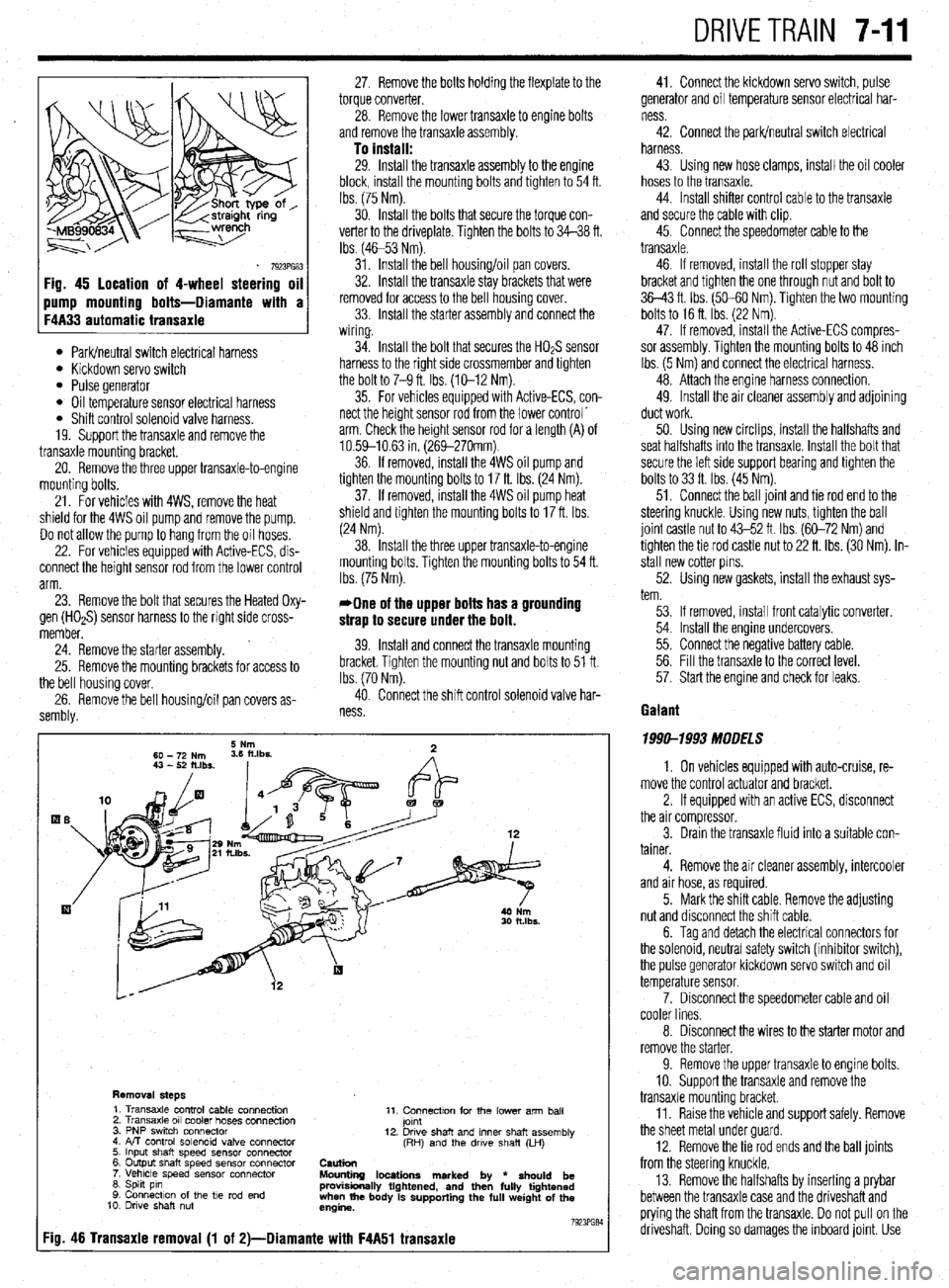
Removal steps 1. Transaxle control cable connection
2. Transaxle 011 cooler hoses connection
3. PNP swrtch connector
4. FvT control solenoid valve connector
5. Input shaft speed sensor connector
6. Output shaft speed sensor connector
7. Vehicle speed sensor connector
6. Spht pin
9. Connection of the tie rod end
10. Drwe shaft nut 11. Connectton for the lower arm ball
jomt
12. Drwe shaft and inner shaft assembly
(RH) and the drwe shaft (LH)
Caution
Mounting locations marked by
l should be
provisionally tightened, and then fully tightened
when the body is supporting the full weight of the
engine.
7923PG84
:io. 46 Transaxie removal (1 of 2)-Diamante with F4A51 transaxie
41. Connect the kickdown servo switch, pulse
generator and oil temperature sensor electrical har-
ness
42. Connect the park/neutral switch electrical
harness.
43. Using new hose clamps, install the oil cooler
hoses to the transaxle.
44. Install shifter control cable to the transaxle
and secure the cable with clip.
45. Connect the speedometer cable to the
transaxle.
46. If removed, install the roll stopper stay
bracket and tighten the one through nut and bolt to
36-43 ft. Ibs. (50-60 Nm). Tighten the two mounting
bolts to 16 ft. Ibs. (22 Nm).
47. If removed, install the Active-ECS compres-
sor assembly. Tighten the mounting bolts to 48 inch
Ibs. (5 Nm) and connect the electrical harness.
48. Attach the engine harness connection.
49. Install the air cleaner assembly and adjoining
duct work.
50. Using new circlips, install the halfshafts and
seat halfshafts into the transaxle. Install the bolt that
secure the left side support bearing and tighten the
bolts to 33 ft. Ibs. (45 Nm).
51. Connect the ball joint and tie rod end to the
steering knuckle. Using new nuts, tighten the ball
joint castle nut to 43-52 ft. Ibs. (60-72 Nm) and
tighten the tie rod castle nut to 22 ft. ibs. (30 Nm). in-
stall new cotter pins.
52. Using new gaskets, install the exhaust sys-
tem.
53. If removed, install front catalytic converter.
54. Install the engine undercovers.
55. Connect the negative battery cable.
56. Fill the transaxle to the correct level.
57. Start the engine and check for leaks.
Gaiant
1999-1993 MODELS
1. On vehicles equipped with auto-cruise, re-
move the control actuator and bracket.
2. If equipped with an active ECS, disconnect
the air compressor.
3. Drain the transaxle fluid into a suitable con-
tainer.
4. Remove the air cleaner assembly, intercooler
and air hose, as required.
5. Mark the shift cable. Remove the adjusting
nut and disconnect the shift cable.
6. Tag and detach the electrical connectors for
the solenoid, neutral safety switch (inhibitor switch),
the pulse generator kickdown servo switch and oil
temperature sensor.
7. Disconnect the speedometer cable and oil
cooler lines.
8. Disconnect the wires to the starter motor and
remove the starter.
9. Remove the upper transaxle to engine bolts.
10. Support the transaxle and remove the
transaxle mounting bracket.
11. Raise the vehicle and support safely. Remove
the sheet metal under guard
12. Remove the tie rod ends and the bail joints
from the steering knuckle.
13. Remove the halfshafts by inserting a prybar
between the transaxle case and the driveshaft and
prying the shaft from the transaxle. Do not pull on the
driveshaft. Doing so damages the inboard joint. Use