1900 MITSUBISHI DIAMANTE battery location
[x] Cancel search: battery locationPage 84 of 408
ENGlNEANDENGlNEOVERHAiL 3-23
8. Remove the camshaft and silent shaft timing
belts. Refer to the timing belt procedure in this sec-
tion
9. Remove the A/C belt idler pulley and pulley
bracket.
10. Remove the alternator brace,
11. Remove the water pump, gasket and O-ring
where the water inlet pipe(s) joins the pump.
To install:
12. Thoroughly clean both gasket surfaces of the
water pump and block.
13. Install a new O-ring into the groove on the
front end of the water inlet pipe and wet with clean
antifreeze only. Do not apply oils or grease to the O-
ring.
14. Using a new gasket, install the water pump
assembly. Tighten bolts with the head mark 4 to 10
ft Ibs. (14 Nm) and bolts with the head mark 7 to 18
ft. Ibs. (24 Nm).
15. Install the A/C pulley and pulley bracket,
16. Install the timing belts. Refer to the timing
belt procedure in this section.
17. Install the engine drive belts.
18. Install the engine mount bracket.
19. Install the engine undercover,
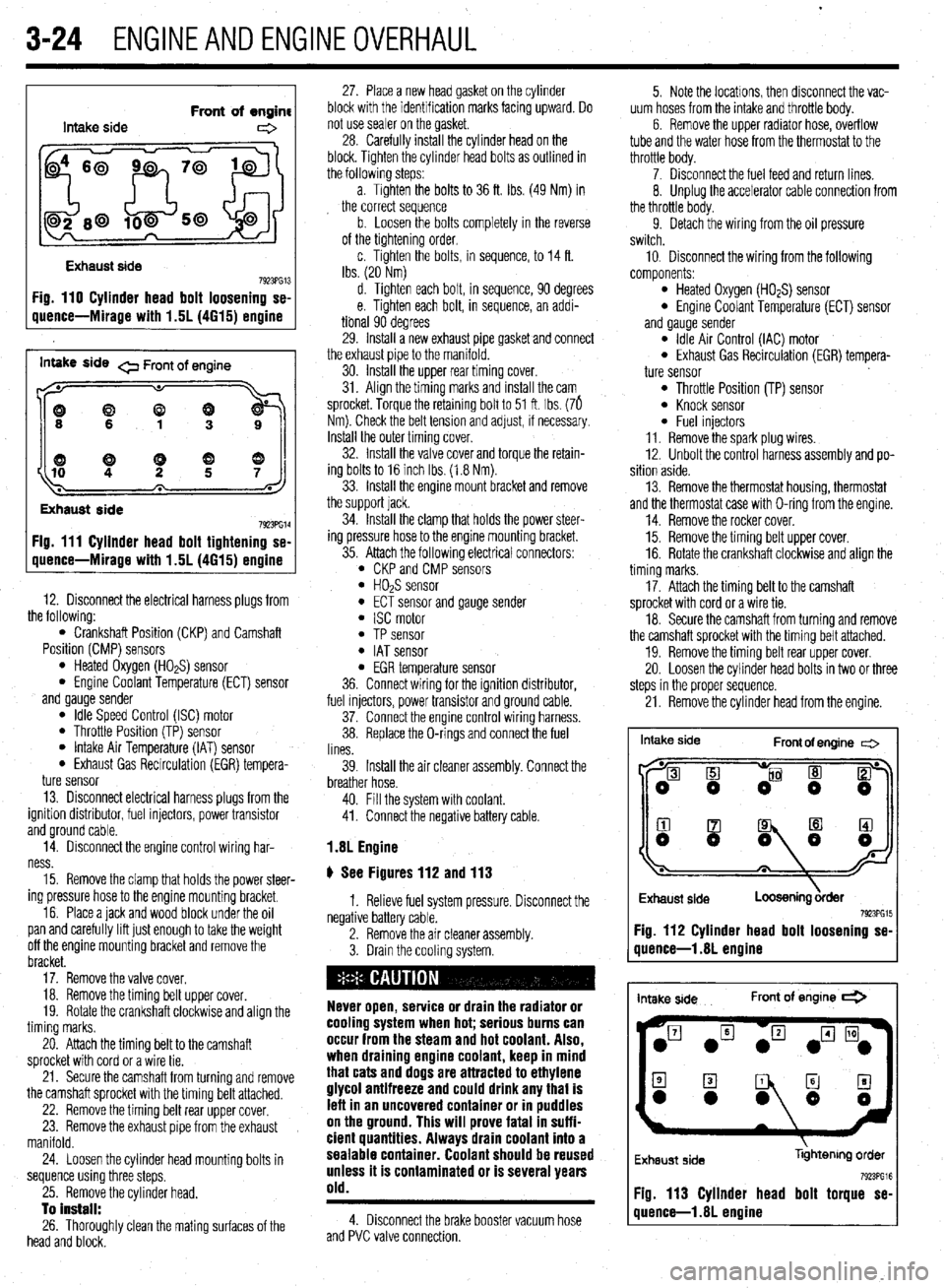
20. Fill the system with coolant.
21. Connect the negative battery cable, run the
vehicle until the thermostat opens and fill the radiator
completely.
22. Once the vehicle has cooled, recheck the
coolant level.
3.OL and 3.5L Engines
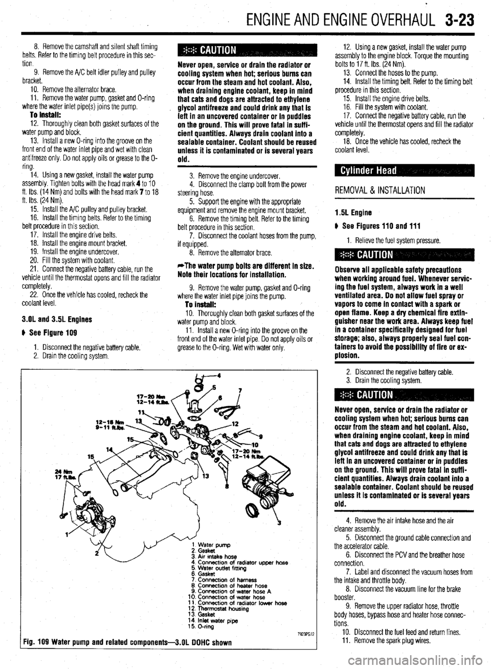
# See Figure 109
1. Disconnect the negative battery cable,
2. Drain the cooling system.
Never open, service or drain the radiator or
cooling system when hot; serious burns can
occur from the steam and hot coolant. Also,
when draining engine coolant, keep in mind
that cats and dogs are attracted to ethylene
glycol antifreeze and could drink any that is
left in an uncovered container or in puddles
on the ground. This will prove fatal in suffi-
cient quantities. Always drain coolant into a
sealable container. Coolant should be reused
unless it is contaminated or is several years
old.
3. Remove the engine undercover.
4. Disconnect the clamp bolt from the power
steering hose.
5. Support the engine with the appropriate
equipment and remove the engine mount bracket.
6. Remove the timing belt. Refer to the timing
belt procedure in this section.
7. Disconnect the coolant hoses from the pump,
if equipped.
8. Remove the alternator brace.
*The water pump bolts are different in size.
Note their locations for installation.
9. Remove the water pump, gasket and O-ring
where the water inlet pipe joins the pump.
To install: 10. Thoroughly clean both gasket surfaces of the
water pump and block.
11. Install a new O-ring into the groove on the
front end of the water inlet pipe. Do not apply oils or
grease to the O-ring. Wet with water only.
Atr Intake hose
Connactlon of’ radlator upper hose
5 Water outlet fming
6. Gasket
7 Connacmn of harness
8 Connection of heater hose
9. Connection of water hose A
10. ConnectIon of water hose
11. Connection of radiator Iowar hose
1 f Thn&ostat housing
14 Inlet water pye
15 O-ring
7923Fw :ig. 109 Water pump and related components-3.01 DOHC shown
12. Using a new gasket, install the water pump
assembly to the engine block. Torque the mounting
bolts to 17 ft. Ibs. (24 Nm).
13. Connect the hoses to the pump.
14. Install the timing belt. Refer to the timing belt
procedure in this section.
15. Install the engine drive belts.
16. Fill the system with coolant.
17. Connect the negative battery cable, run the
vehicle until the thermostat opens and fill the radiator
completely.
18. Once the vehicle has cooled, recheck the
coolant level.
REMOVAL & INSTALLATION
1.5L Engine
u See Figures 110 and 111
1. Relieve the fuel system pressure.
Observe all applicable safety precautions
when working around fuel. Whenever servic-
ing the fuel system, always work in a well
ventilated area. Do not allow fuel spray or
vapors to come in contact with a spark or
open flame. Keep a dry chemical fire extin-
guisher near the work area. Always keep fuel
in a container specifically designed for fuel
storage; also, always properly seal fuel con-
tainers to avoid the possibility of fire or ex-
plosion.
2. Disconnect the negative battery cable.
3. Drain the cooling system.
Never open, service or drain the radiator or
cooling system when hot; serious burns can
occur from the steam and hot coolant. Also,
when draining engine coolant, keep in mind
that cats and dogs are attracted to ethylene
glycol antifreeze and could drink any that is
left in an uncovered container or in puddles
on the ground. This will prove fatal in suffi-
cient quantities. Always drain coolant into a
sealable container. Coolant should be reused
unless it is contaminated or is several years
old.
4. Remove the air intake hose and the air
cleaner assembly.
5. Disconnect the ground cable connection and
the accelerator cable.
6. Disconnect the PCV and the breather hose
connection.
7. Label and disconnect the vacuum hoses from
the intake and throttle body.
8. Disconnect the vacuum line for the brake
booster.
9. Remove the upper radiator hose, throttle
body hoses, bypass hose and heater hose connec-
tions
10. Disconnect the fuel feed and return lines.
11. Remove the spark plug wires.
Page 85 of 408
3-24 ENGINEANDENGINEOVERHAUL
Intake side Front of engine
e
Exhaust side
7923PG13 Fig. 110 Cylinder head bolt loosening se-
uuence-Mirage with 1.5L (4615) ermine
inwe side 0 Front of engine
((9
Exhaust side
7923PG14 Fig. 111 Cyllnder head bolt tightening se-
quence-Mirage with 1.5L (4615) engine
12. Disconnect the electrical harness plugs from
the following:
l Crankshaft Position (CKP) and Camshaft
Position (CMP) sensors
l Heated Oxygen (HO*S) sensor l Engine Coolant Temperature (ECT) sensor
and gauge sender
l Idle Speed Control (ISC) motor l Throttle Position (TP) sensor l Intake Air Temperature (IAT) sensor l Exhaust Gas Recirculation (EGR) tempera-
ture sensor
13. Disconnect electrical harness plugs from the
ignition distributor, fuel injectors, power transistor
and ground cable.
14. Disconnect the engine control wiring har-
ness.
15. Remove the clamp that holds the power steer-
ing pressure hose to the engine mounting bracket.
16. Place a jack and wood block under the oil
pan and carefully lift just enough to take the weight
off the engine mounting bracket and remove the
bracket.
17. Remove the valve cover.
18. Remove the timing belt upper cover.
19. Rotate the crankshaft clockwise and align the
timing marks.
20. Attach the timing belt to the camshaft
sprocket with cord or a wire tie.
21. Secure the camshaft from turning and remove
the camshaft sprocket with the timing belt attached.
22. Remove the timing belt rear upper cover.
23. Remove the exhaust pipe from the exhaust
manifold.
24. Loosen the cylinder head mounting bolts in
sequence using three steps.
25. Remove the cylinder head.
To install:
26. Thoroughly clean the mating surfaces of the
head and block. 27. Place a new head gasket on the cylinder
block with the identification marks facing upward. Do
not use sealer on the gasket.
28. Carefully install the cylinder head on the
block. Tighten the cylinder head bolts as outlined in
the followlng steps:
a. Tighten the bolts to 36 ft. Ibs. (49 Nm) in
the correct sequence
b. Loosen the bolts completely in the reverse
of the tightening order,
c. Tighten the bolts, in sequence, to 14 ft.
Ibs. (20 Nm)
d. Tighten each bolt, in sequence, 90 degrees
e. Tighten each bolt, in sequence, an addi-
tional 90 degrees
29. Install a new exhaust pipe gasket and connect
the exhaust pipe to the manifold.
30. Install the upper rear timing cover.
31. Align the timing marks and install the cam
sprocket. Torque the retaining bolt to 51 ft. Ibs. (76
Nm). Check the belt tension and adjust, if necessary.
Install the outer timing cover.
32. Install the valve cover and torque the retain-
ing bolts to 16 inch Ibs. (1.8 Nm).
33. Install the engine mount bracket and remove
the support jack.
34. Install the clamp that holds the power steer-
ing pressure hose to the engine mounting bracket.
35. Attach the following electrical connectors:
l CKP and CMP sensors l HOPS sensor l ECT sensor and gauge sender l ISC motor l TP sensor l IAT sensor l EGR temperature sensor
36. Connect wiring for the ignition distributor,
fuel injectors, power transistor and ground cable.
37. Connect the engine control wiring harness.
38. Replace the O-rings and connect the fuel
lines.
39. Install the air cleaner assembly. Connect the
breather hose.
40. Fill the system with coolant.
41. Connect the negative battery cable.
1.8L Engine
# See Figures 112 and 113
1. Relieve fuel system pressure. Disconnect the
negative battery cable.
2. Remove the air cleaner assembly.
3. Drain the cooling system.
Never open, service or drain the radiator or
cooling system when hot; serious burns can
occur from the steam and hot coolant. Also,
when draining engine coolant, keep in mind
that cats and dogs are attracted to ethylene
glycol antifreeze and could drink any that is
lefl in an uncovered container or in puddles
on the ground. This will prove fatal in suffi-
cient quantities. Always drain coolant into a
sealable container. Coolant should be reused
unless it is contaminated or is several years
old.
4. Disconnect the brake booster vacuum hose
and PVC valve connection. 5. Note the locations, then disconnect the vac-
uum hoses from the intake and throttle body.
6. Remove the upper radiator hose, overflow
tube and the water hose from the thermostat to the
throttle body.
7. Disconnect the fuel feed and return lines.
8. Unplug the accelerator cable connection from
the throttle body.
9. Detach the wiring from the oil pressure
switch.
10, Disconnect the wiring from the following
components:
l Heated Oxygen (HO*S) sensor l Engine Coolant Temperature (ECT) sensor
and gauge sender
l Idle Air Control (IAC) motor l Exhaust Gas Recirculation (EGR) tempera-
ture sensor
l Throttle Position (TP) sensor l Knock sensor l Fuel injectors
11. Remove the spark plug wires.
12. Unbolt the control harness assembly and po-
sition aside.
13. Remove the thermostat housing, thermostat
and the thermostat case with O-ring from the engine.
14. Remove the rocker cover.
15. Remove the timing belt upper cover.
16. Rotate the crankshaft clockwise and align the
timing marks.
17. Attach the timing belt to the camshaft
sprocket with cord or a wire tie.
18. Secure the camshaft from turning and remove
the camshaft sprocket with the timing belt attached.
19. Remove the timing belt rear upper cover.
20. Loosen the cylinder head bolts in two or three
steps in the proper sequence.
21. Remove the cylinder head from the engine.
Intake side
Front of engine c=>
I
Exhaust side
Loosening &der 7923PG15 Fig. 112 Cylinder head bolt loosening se-
quence-l .8L engine
intake side Front of engine *
Exhaust side libhtenng order
Fig. 113 Cylinder head bolt torque se-
quence-l .8L engine
Page 86 of 408
ENGINEANDENGINEOVERHAUL 3-25
When removina the cvlinder head. take care
not to bend or iamag;! the plug guide. The
plug guide can not be replaced.
To install:
22. Thoroughly clean the mating surfaces of the
head and block.
23. Place a new head gasket on the cylinder
block with the identification marks facing upward. Do
not use sealer on the gasket.
24. Carefully install the cylinder head on the
block.
25. Measure the cylinder head bolts prior to in-
stallation Replace any that exceed 3.795 in.
(96.4mm)
26. Apply a small amount of engine oil to the
thread section of the bolt and install so the chamfer
of the washer faces upward.
27. Tighten the cylinder head bolts as follows:
a. In the proper tightening sequence, torque
bolts to 54 ft. Ibs. (75 Nm).
b. In the reverse order of the tightening se-
quence, fully loosen all bolts.
c In the proper trghtening sequence, torque
bolts to 14 ft. Ibs. (20 Nm).
d. In the proper tightening sequence, tighten
bolts 1/4 turn (90 degrees).
e. In the proper tightening sequence, tighten
bolts an additional 1/4 turn (90 degrees).
28. Install the camshaft sprocket and tighten the
bolt to 65 ft. Ibs (90 Nm), while holding the sprocket
in place using the appropriate wrench. Confirm
proper timing mark alignment.
29. Install the upper timing belt cover and rocker
cover. Torque the rocker cover bolts to 29 inch Ibs.
(3 Nm).
30. Loosen the water pipe mounting bolt for ease
of thermostat housing installation.
31. Apply a thin bead of sealant MD970389 or
equivalent, to the water tube connection on the ther-
mostat case.
32. Apply a small amount of water to the O-ring
of the water inlet pipe and press the thermostat case
assembly onto the water inlet pipe. Install the ther-
mostat case assembly mounting bolt tightening to 16
ff. Ibs. (22 Nm).
l ECT sensor and gauge sender l IAC motor 33. Tighten the water pipe mounting bolt.
34. Install the thermostat into the housing so the
jiggle valve is located at the top. Tighten the housing
bolts to 10 ft. Ibs (14 Nm).
35. Attach the wiring to the following compo-
nents:
l HO& sensor
l EGR temperature sensor l TP sensor l Knock sensor l Fuel injectors
36. Connect the upper radiator hose to the ther-
mostat housing.
37. Connect the accelerator cable connection to
the throttle body.
38. Connect the oil pressure switch.
39. Install the spark plug wires,
40. Connect the control harness assembly.
41. Replace the O-ring for the high pressure hose
and install a new clamp on the return hose and re-
connect the fuel lines. 42. Install the air intake hose. Connect the
breather hose and air cleaner case cover
43. Reconnect the brake booster and the PCV
vacuum hoses.
44. Fill the system with coolant.
45. Connect the negative battery cable
2.01 SOHC Engine
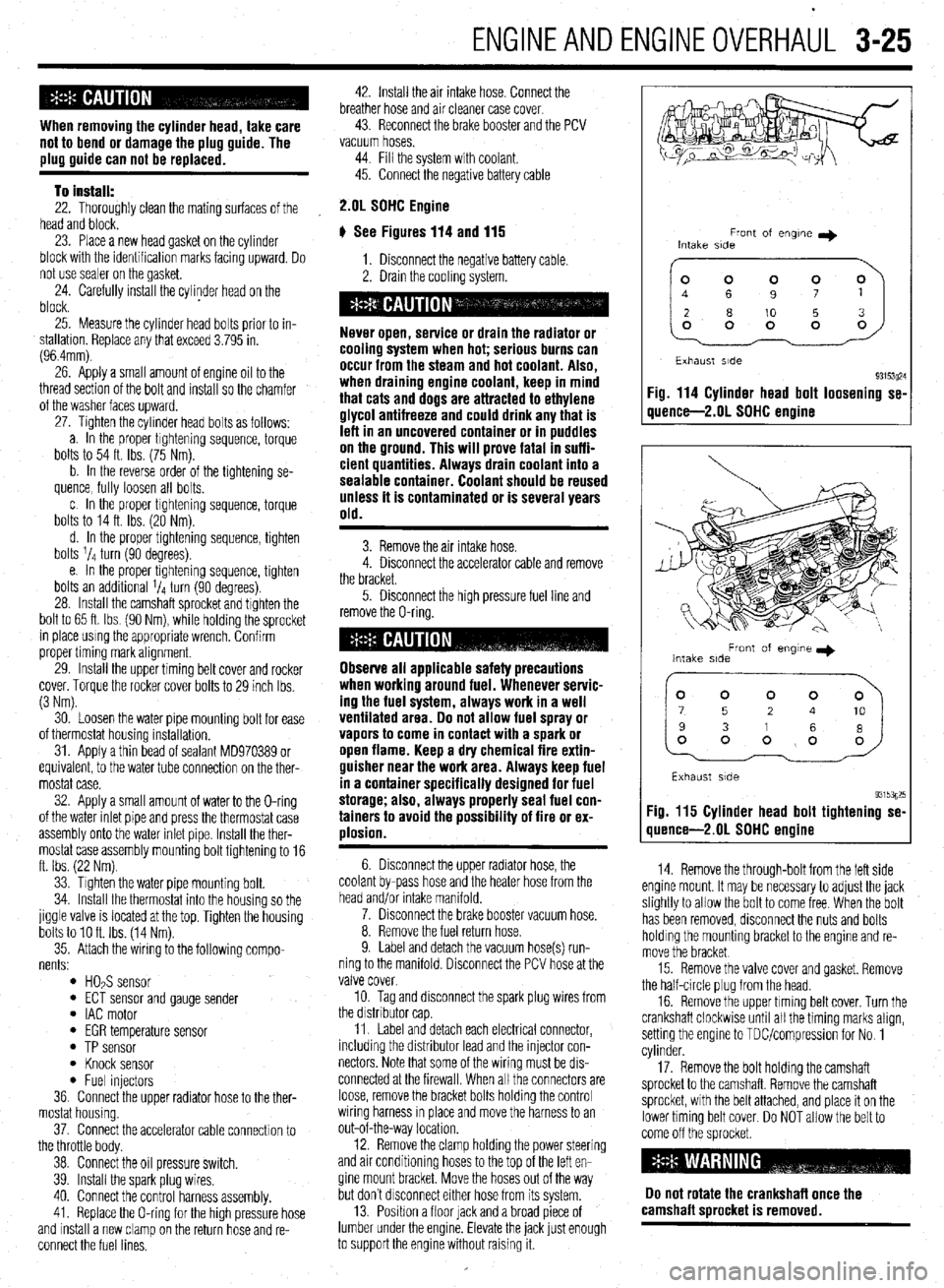
# See Figures 114 and 115
1. Disconnect the negative battery cable.
2. Drain the coolrng system.
Never open, service or drain the radiator or
cooling system when hot; serious burns can
occur from the steam and hot coolant. Also,
when draining engine coolant, keep in mind
that cats and dogs are attracted to ethylene
glycol antifreeze and could drink any that is
left in an uncovered container or in puddles
on the ground. This will prove fatal in suffi-
cient quantities. Always drain coolant into a
sealable container. Coolant should be reused
unless it is contaminated or is several years
old.
3. Remove the air intake hose.
4. Disconnect the accelerator cable and remove
the bracket.
5. Disconnect the high pressure fuel line and
remove the O-ring.
Observe all applicable safety precautions
when working around fuel. Whenever servic-
ing the fuel system, always work in a well
ventilated area. Do not allow fuel spray or
vapors to come in contact with a spark or
open flame. Keep a dry chemical fire extin-
guisher near the work area. Always keep fuel
in a container specifically designed for fuel
storage; also, always properly seal fuel con-
tainers to avoid the possibility of fire or ex-
plosion.
6. Disconnect the upper radiator hose, the
coolant by-pass hose and the heater hose from the
head and/or intake manifold.
7. Disconnect the brake booster vacuum hose.
8. Remove the fuel return hose.
9. Label and detach the vacuum hose(s) run-
ning to the manifold. Disconnect the PCV hose at the
valve cover.
10. Tag and disconnect the spark plug wires from
the drstnbutor cap
11. Label and detach each electrical connector,
including the distributor lead and the injector con-
nectors Note that some of the wiring must be drs-
connected at the firewall. When all the connectors are
loose, remove the bracket bolts holding the control
wiring harness rn place and move the harness to an
out-of-the-way location.
12. Remove the clamp holding the power steering
and air conditioning hoses to the top of the left en-
gine mount bracket. Move the hoses out of the way
but don’t drsconnect either hose from its system.
13. Position a floor lack and a broad piece of
lumber under the engine. Elevate the jack lust enough
to support the engine without raising it.
Front of engne I)
Intake side
~~
Exhaust side
93153~24 Fig. 114 Cylinder head bolt loosening se-
quence-2.01 SOHC engine
Front of engme I)
Intake side
Exhaust side
93153g25 Fig. 115 Cylinder head bolt tightening se-
quence-2.01 SDHC engine
14. Remove the through-bolt from the left side
engine mount. It may be necessary to adjust the jack
slightly to allow the bolt to come free When the bolt
has been removed, disconnect the nuts and bolts
holding the mounting bracket to the engine and re-
move the bracket
15. Remove the valve cover and gasket. Remove
the half-circle plug from the head.
16. Remove the upper timing belt cover. Turn the
crankshaft clockwise until all the timing marks align,
setting the engine to TDUcompression for No. 1
cylinder.
17. Remove the bolt holding the camshaft
sprocket to the camshaft. Remove the camshaft
sprocket, with the belt attached, and place it on the
lower timing belt cover. Do NOT allow the belt to
come off the sprocket
Do not rotate the crankshaft once the
camshaft sorocket is removed.
Page 87 of 408
3-26 ENGINEANDENGINEOVERHAUL
18. Remove the self-locking nuts and the small
retaining bolt holding the exhaust pipe to the bottom
of the exhaust manifold. Separate the pipe from the
manifold and remove the gasket.
19. Remove the bolts holding the support brace
to the bottom of the intake manifold.
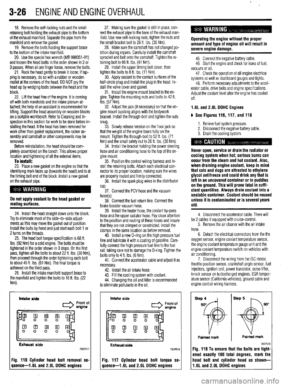
20. Use the special hex wrench (MB 998051-01)
and loosen the head bolts in the order shown in 2 or
3 passes. When all are finger loose, remove the bolts.
21. Rock the head gently to break it loose; if tap-
ping is necessary, do so with a rubber or wooden
mallet at the corners of the head. DO NOT pry the
head up by wedging tools between the head and the
block.
22. Lift the head free of the engine. It is coming
off with both manifolds and the intake plenum at-
tached; the help of an assistant is recommended for
lifting. Support the head assembly on wooden blocks
on a suitable workbench. Refer to Cleaning and In-
spection in this section for work to be done before in-
stalling the head. If the head has been removed for
work other than gasket replacement, the rocker as-
sembly and camshaft or other components may be
removed.
Before reinstallation, the head should be com-
pletely assembled on the bench. This allows proper
location and tightening of all the external items.
To install: 23. Place a new gasket on the engine so that the
identifying mark faces up (towards the head) and is at
the timing belt end of the block. Install a new gasket
on the exhaust pipe.
Do not apply sealant to the head gasket or
mating surfaces.
24. Install the head straight down onto the block.
Try to eliminate most of the side-to-side adjust-
ments as this may move the gasket out of position.
Install the bolts by hand and just start each bolt 1 or
2 turns on the threads.
25. The head bolt torque specification is 68 ft.
Ibs. (92 Nm) for a cold engine. The bolts must be
tightened in the order shown in 3 steps. On the first
pass, tighten all the bolts to about 22 ft. Ibs. (30 Nm),
then proceed through the order tightening each bolt
to about 45 ft. Ibs. (61 Nm). The final torque is
achieved on the third pass.
26. Install the intake manifold support brace to
the manifold and tighten the bolts to 16 ft. Ibs. (22
Nm). 27. Making sure the gasket is still in place, con-
nect the exhaust pipe to the base of the exhaust man-
ifold. Use new self-locking nuts; tighten the nuts and
the small bracket bolt to 26 ft. Ibs. (35 Nm).
28. Make sure the camshaft has not changed po-
sition during repalrs. Carefully install the camshaft
sprocket and belt onto the camshaft. Tighten the re-
taining bolt to 66 ft. Ibs. (91 Nm).
29. Install the upper timing belt cover, then
tighten the bolts to 8 ft. Ibs. (11 Nm).
30. Apply sealant to the contact surfaces of the
half-circle plug and install the plug in the head In-
stall the valve cover and gasket.
31. Install the engine mount bracket to the en-
gine. Tighten the mounting nuts and bolts to 42 ft.
Ibs. (57 Nm).
32. Adjust the jack (if necessary) so that the en-
gine mount bushing aligns with the bodywork
bracket. Install the through-bolt and tighten the nuts
snug.
33. Slowly release tension on the floor jack so
that the weight of the engine bears fully on the
mount. Tighten the through-bolt to 52 ft. Ibs. (71
Nm) and the small safety nut to 26 ft. tbs. (36 Nm).
34. Install the bracket holding the power steering
hose and air conditioning hose to the top of the en-
gine mount.
35. Position the control wiring harness and in-
stall the retaining bolts. Attach each electrical con-
nector to its proper location, making sure the wires
are properly routed and firmly connected.
36. Install the spark plug wires in the distributor
cap.
37. Connect the PCV hose and the vacuum
hose(s).
38. Connect the fuel return line. Connect the
brake booster vacuum hose.
39. Install the heater hose, the coolant by-pass
hose and.the upper radiator hose. Pay close attention
to the position and routing of these hoses and insure
that they are not crimped or constricted. Install the
clamps in the same location as before removal.
40. Install a new O-ring on the high pressure fuel
line and lubricate it with a coating of gasoline. Care-
fully connect the high pressure fuel line to the fuel
rail, taking care not to damage the O-ring. Tighten the
bolts only to 4 ft. Ibs. (6 Nm).
41. Connect the accelerator cable and adjust it as
necessary.
42. Install the air intake hose.
43. Fill the cooling system with coolant.
44. Changing the oil and filter is recommended
to eliminate pollutants in the oil.
Intake side
I Front of
engine
Exhaust side
Fig. 116 Cylinder head bolt removal se-
quence-l .6L and 2.OL DDHC engines intake
side
Front of
entine
Exhaust side 7923PG18
Fig. 117 Cylinder head bolt torque se-
quence-l .6L and 2.OL DDHC engines Operating the engine without the proper
amount and type of engine oil will result in
severe engine damage.
45. Connect the negative battery cable.
46. Start the engine and check for leaks of fuel,
vacuum or oil.
47. Check the operation of all engine electrical
systems as well as dashboard gauges and lights.
48. Perform necessary adjustments to the accel-
erator cable, drive belts and engine specifications.
Adjust the coolant level after the engine has cooled
Off.
1.6L and 2.OL DDHC Engines
ti See Figures 116,117, and 116
1. Relieve fuel system pressure.
2. Disconnect the negative battery cable.
3. Drain the cooling system.
Never open, service or drain the radiator or
cooling system when hot; serious burns can
occur from the steam and hot coolant. Also,
when draining engine coolant, keep in mind
that cats and dogs are attracted to ethylene
glycol antifreeze and could drink any that is
left in an uncovered container or in puddles
on the ground. This will prove fatal in suffi-
cient quantities. Always drain coolant into a
sealable container. Coolant should be reused
unless it is contaminated or is several years
old.
4. Disconnect the accelerator cable. There will
be 2 cables if equipped with cruise-control.
5. Remove the air cleaner with the air intake
hose.
6. Detach the electrical connectors from the the
oxygen sensor, engine coolant temperature sensor,
the engine coolant temperature gauge unit and the
engine coolant temperature switch on vehicles with
air conditioning.
7. Disconnect the wiring from the ISC motor,
throttle position sensor, crankshaft angle sensor, fuel
injectors, ignition coil, power transistor, noise filter,
knock sensor on turbocharged engines, EGR temper-
ature sensor (California vehicles), ground cable and
engine control wiring harness.
Painted mark Painted mark
Fig. 116 To ensure that the bolts are tight-
ened exactly 160 total degrees, mark the
11.6L and 2.OL DDHC engines head bolt and cylinder head as shown-
Page 107 of 408
3-46 ENGINEANDENGINEOVERHAUL
29. Install the engine support bracket and secure
using mounting bolts in their original location. Lubri-
cate the reaming area of the reamer bolt and tighten
slowly.
30. Install the idler pulley.
31. Install the engine mount bracket. Remove the
engine support fixture.
32. Make sure all pieces of packing are posi-
tioned in the inner grooves of the upper cover and in-
stall.
33. Connect the brake fluid level sensor.
34. Install the crankshaft pulley. Tighten the bolt
to 130-137ft. Ibs. (180-190 Nm).
35. install the belt tensioner assembly and the
power steering belt.
36 install the air hose and pipe.
37 Install the alternator.
38. Install the cruise control actuator.
39. Install the engine undercover.
40. Connect the negative battery cable.
199546 MODELS
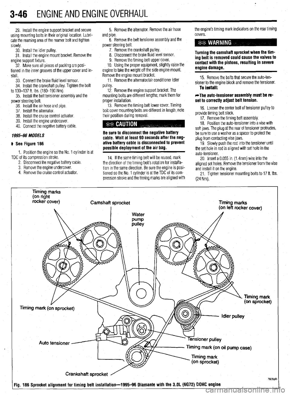
# See Figure 186
1, Position the engine so the No. 1 cylinder is at
TDC of its compression stroke.
2. Disconnect the negative battery cable.
3. Remove the engine undercover.
4 Remove the cruise control actuator. 5. Remove the alternator, Remove the air hose the engine’s timing mark indicators on the rear timing
and pipe.
6. Remove the belt tensioner assembly and the
power steering belt.
7. Remove the crankshaft pulley.
8. Disconnect the brake fluid level sensor.
9. Remove the timing belt upper cover.
10. Using the proper equipment, slightly raise the
engine to take the weight off the side engine mount.
Remove the engine mount bracket.
11, Remove the alternator/air conditioner idler
..,,ll^,. covers.
Turning the camshaft sprocket when the tim-
ing belt is removed could cause the valves to
contact with the pistons, resulting in severe
engine damage.
15. Remove the bolts that secure the auto-ten-
sioner to the engine block and remove the tensioner.
pu,ey. 12. Remove the engine support bracket. The To install:
mounting bolts are different lengths; mark them for
orooer installation. *The auto-tensioner assembly must be re-
set to correctlv adiust belt tension. , . 13. Remove the timing belt lower cover. Timing
bolt cover mounting bolts are different in length, note
their position during removal.
Be sure to disconnect the negative battery
cable. Wait at least 90 seconds after the neg-
ative battery cable is disconnected to prevent
possible deployment of the air bag.
14. If the same timing belt WIII be reused, mark
the direction of the trming belts rotation for installa-
tion In the same direction, Be sure the engine is posi-
tioned so the No. 1 cylinder is at the TDC of its com-
pression stroke and the timing marks are aligned with _ -
16. Loosen the center bolt of tensioner pulley to
provide timing belt slack.
17. Remove the timing belt assembly.
18. Posrtion the auto-tensioner into a vise with
soft iaws. The olua at the rear of tensioner protrudes,
be sure to usea v&her as a spacer to protect the
plug from contacting vise jaws.
19. Slowly push the rod mto the tensioner until
the set hole in rod is aligned with set hole in the
auto-tensioner.
20. Insert a 0.055 in. (1.4mm) wire into the
aligned set holes, Remove the tensioner from the vise
and install it on the engine.
21. Tighten tensioner mounting bolts to 17 ft. Ibs.
(24 Nm).
Timing marks
(on right
rocker cover)
Camshaft sprocket
Timing marks
mark (on oil pump case)
Crankshaft sprocket
Fig. 186 Sprocket alignment for timing belt installation-1995116 Diamante with the 3.N (6672) DDDD engine
Page 112 of 408
ENGlNEANDENGlNEOVERHALiL 3-51
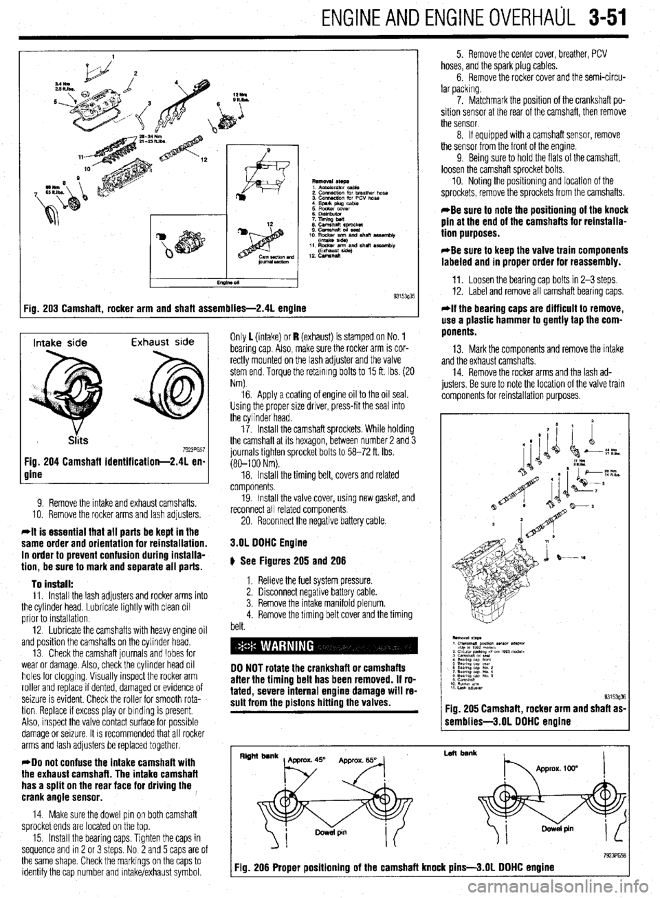
:ig. 203 Camshaft, rocker arm and shaft assemblies-2.41 engine 9315393'
Intake side Exhaust side
7923PG57 Fig. 204 Camshaft identification-2.41 en-
gine
9. Remove the intake and exhaust camshafts.
10. Remove the rocker arms and lash adjusters
*It is essential that all parts be kept in the
same order and orientation for reinstallation.
In order to prevent confusion during installa-
tion, be sure to mark and separate all parts.
To install:
11. Install the lash adjusters and rocker arms into
the cylinder head. Lubricate lightly with clean oil
prior to installation.
12. Lubricate the camshafts with heavy engine oil
and position the camshafts on the cylinder head.
13 Check the camshaft journals and lobes for
wear or damage. Also, check the cylinder head oil
holes for clogging. Visually inspect the rocker arm
roller and replace if dented, damaged or evidence of
seizure is evident. Check the roller for smooth rota-
tion. Replace If excess play or binding is present.
Also, inspect the valve contact surface for possible
damage or seizure. It is recommended that all rocker
arms and lash adjusters be replaced together.
*Do not confuse the intake camshaft with
the exhaust camshaft. The intake camshaft
has a split on the rear face for driving the ,
crank angle sensor.
14. Make sure the dowel pin on both camshaft
sprocket ends are located on the top.
15. Install the bearing caps. Tighten the caps in
sequence and rn 2 or 3 steps. No 2 and 5 caps are of
the same shape. Check the markings on the caps to
identify the cap number and intake/exhaust symbol. Only 1 (intake) or I? (exhaust) is stamped on No. 1
bearing cap Also, make sure the rocker arm is cor-
rectly mounted on the lash adjuster and the valve
stem end. Torque the retaining bolts to 15 ft. Ibs. (20
Nm).
16. Apply a coating of engine oil to the oil seal.
Using the proper size driver, press-fit the seal into
the cylinder head.
17. Install the camshaft sprockets. While holding
the camshaft at its hexagon, between number 2 and 3
journals tighten sprocket bolts to 58-72 ft. Ibs.
(80-l 00 Nm).
18. Install the timing belt, covers and related
components.
19. Install the valve cover, using new gasket, and
reconnect all related components
20. Reconnect the negative battery cable.
3.OL DOHC Engine
# See Figures 205 and 206
1. Relieve the fuel system pressure.
2. Disconnect negative battery cable.
3. Remove the intake manifold plenum.
4. Remove the timing belt cover and the timing
belt.
DO NOT rotate the crankshaft or camshafts
after the timing belt has been removed. If ro-
tated, severe internal engine damage will re-
sult from the pistons hitting the valves.
5. Remove the center cover, breather, PCV
hoses, and the spark plug cables.
6. Remove the rocker cover and the semi-circu-
lar packing.
7. Matchmark the position of the crankshaft po-
sition sensor at the rear of the camshaft, then remove
the sensor.
8. If equipped with a camshaft sensor, remove
the sensor from the front of the engine.
9 Being sure to hold the flats of the camshaft,
loosen the camshaft sprocket bolts.
10. Noting the positionmg and location of the
sprockets, remove the sprockets from the camshafts.
*Be sure to note the positioning of the knock
pin at the end of the camshafts for reinstalla-
tion purposes.
*Be sure to keep the valve train components
labeled and in proper order for reassembly.
11. Loosen the bearing cap bolts in 2-3 steps.
12. Label and remove all camshaft bearing caps.
*If the bearing caps are difficult to remove,
use a plastic hammer to gently tap the com-
ponents.
13. Mark the components and remove the intake
and the exhaust camshafts.
14. Remove the rocker arms and the lash ad-
justers. Be sure to note the location of the valve train
components for reinstallation purposes.
1 semblies-3.01 DOHC engine
I
Left bank
7923PG58 Fig. 206 Proper positioning of the camshaft knock pins-3.01 DOHC engine
Page 148 of 408
,
DRIVEABILITYAND EMISSIONS CONTROLS 4-5
Fig. 16 Remove the canister retaining bolts
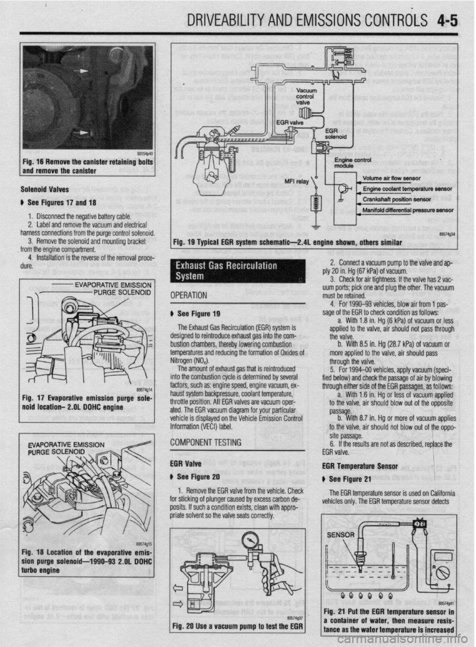
and remove the canister
Solenoid Valves
u See Figures 17 and 18
1 b Disconnect the negative battery cable.
2. Label and remove the vacuum and electrical
harness connections from the purge control solenoid.
3. Remove the solenoid and mounting bracket
from the engine compartment.
4. Installation is the reverse of the removal proce-
dure.
I
- EVAPORATIVE EMISSION
Fig. 18 location of the evaporative emis-
purge solenoid-1990-93 2.OL DDHC
Volume air flow seneftr I
I Manifold diierential pressure m
&a$34
Fig. 19 Typical EGR system schematie-2.4L engine shown, others similar
IPERATION uum ports; pick one and plug the other. The vacuum
must be retained.
1 See Figure 19
The Exhaust Gas Recirculation (EM) system is
lesigned to reintroduce exhaust gas into the com-
ttii valve.
rustion chambers, thereby lowering combustion b. With 8.5 in. Hg (28.7 kPa) of vacuum or
emperatures and reducing the formation of Oxides of more applied to the valve, air should pass 4. For 1990-93 vehicles. blow air from 1 oas-
sage of the EGR to check condition as foffows--
a. With 1.8 in. Hg (6 kPa) of vacuum or less
aoolied to the valve. air should not oass throuah
litrogen (NO,).
The amount of exhaust gas that is reintroduced
Ito the combustion cycle is determined by several
actors, such as: engine speed, engine vacuum, ex-
raust system backpressure, coolant temperature,
Irottle position. All EGR valves are vacuum oper-
ted. The EGR vacuum diagram for your particular
chicle is displayed on the Vehicle Emission Control
iformation (VECI) label. through the valve.
5. For 1994-00 vehicles, apply vacuum (speci-
fied below) and check the passage of air by blowing
through either side of the EGR passages, as follows:
a. With 1 .?I in. Hg or less of vacuum applied
to the valve, air should blow out of the opposite
passa e.
b. %ith 8.7 in. Hg or more of vacuum applies
to the valve, air should not blow out of the oppo-
:OMPONENTTESTiNG site passage.
6. If the results are not as described, replace the
EGR valve.
iGR Valve
t See Figure 20
1. Remove the EGR valve from the vehicle. Check
I”..““.
:or sticking of plunger caused by excess carbon de-
losits. If such a condition exists, clean with appro- EGR Temperature Lan*nr
u See Figure 21
The EGR temperature sensor is used on California
vehicles only. The EGR temperature sensor detects
Fig. 20 Use a vacuum pump to test the EGR
I I
a coni tance i of water. then measure resis-
I ms the water temperature is increased
Page 150 of 408
.
DRIVEABILITYAND EMISSIONS CONTROLS 4-7
6. Clean the mating surfaces on the valve and
the engine. Make sure to remove all gasket material.
7. Inspect the valve for a sticking plunger,
caused by excess carbon deposits. If such a condi-
tion exists, clean with appropriate solvent so valve
seats correctly.
To install:
8. Install EGR valve with a new gasket in place.
9. Install the mounting bolts and tighten as fol- EGR Solenoid
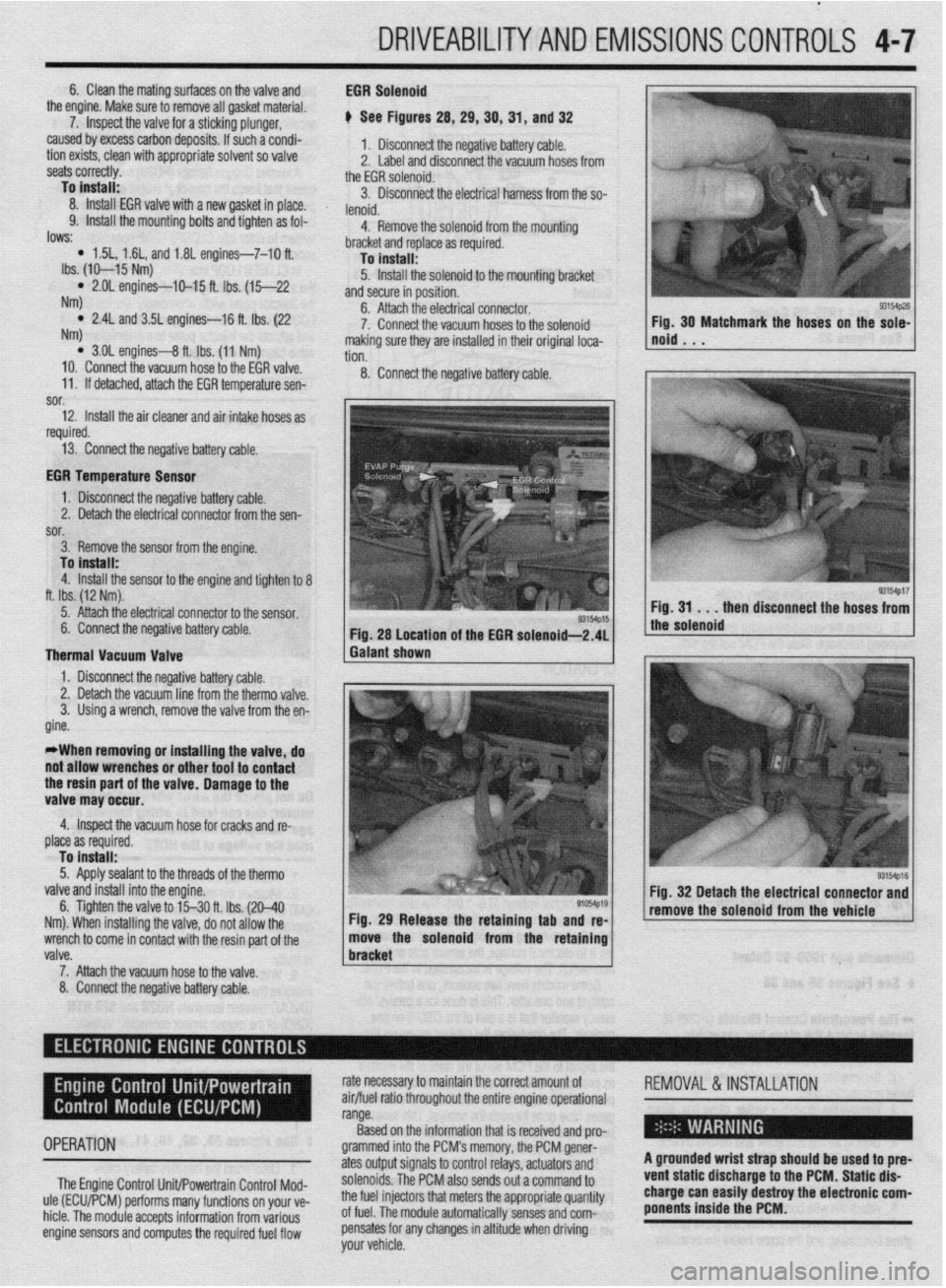
e See Figures 28, 29, 39, 31, and 32
1. Disconnect the negative battery cable.
2. Label and disconnect the vacuum hoses from
the EGR solenoid.
3. Disconnect the electrical harness from the so-
lenoid.
4. Remove the solenoid from the mountino
lows: * 1.5L, 1.6L, and 1.81 engines-7-10 ft.
Ibs. (IO-15 Nm)
l 2.OL engines-IO-15 ft. Ibs. (15-22
NW
l 2.4L and 3.5L engines-16 ft. Ibs. (22
NW
l 3.01 engines-8 ft. Ibs. (11 Nm)
10. Connect the vacuum hose to the EGR valve.
11. If detached, attach the EGR temperature sen- -
bracket and replace as required.
To install:
5. Install the solenoid to the mounting bracket
and secure in position.
6. Attach the electrical connector.
7. Connect the vacuum hoses to the solenoid
making sure they are installed in their original loca-
tion.
8. Connect the negative battery cable.
sor.
12. Install the air cleaner and air intake hoses as
I
required.
13. Connect the negative battery cable.
EGR Temperature Sensor
1. Disconnect the negative battery cable.
2. Detach the electrical connector from the sen-
sor.
3. Remove the sensor from the engine.
To install:
4. Install the sensor to the engine and tighten to 8
ft. Ibs. (12 Nm).
5. Attach the electrical connector to the sensor.
6. Connect the negative battery cable.
Thermal Vacuum Valve
1. Disconnect the negative battery cable. Fig. 28 Location of the EGR solenoid-2.41
Galant shown
valve.
7. Attach the vacuum hose to the valve 1 bracket 6. Tighten the valve to l‘j30 ft. Ibs. (20-40
91054p19
Nm). When installing the valve, do not allow the Fig. 29 Release the retaining tab and re-
wrench to come in contact with the resin part of the move the solenoid from the retaining Fig, 30 Matchmark the hoses on the sole-
noid . . .
8. Connect the negative battery cable.