1900 MITSUBISHI DIAMANTE clutch
[x] Cancel search: clutchPage 6 of 408
GENERALINFORMATIONAND MAlNTENAiCE I-7
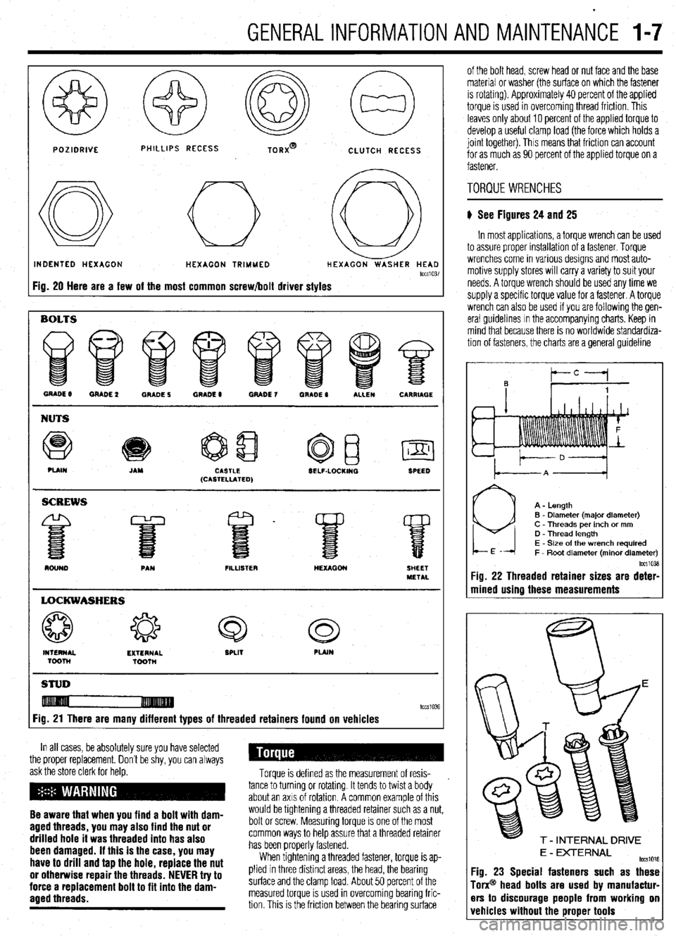
POZIDRIVE PHILLIPS RECESS
TORX@
CLUTCH RECESS
INDENTED HEXAGON HEXAGON TRIMMED HEXAGON WASHER HEAD
tccs1037
Fig. 20 Here are a few of the most common screw/bolt driver styles
GRADE 8 MADE 2 GRADE 5 QRADE 8 GRADE 7 WADE 0 ALLEN CARRIAGE
NUTS
Q e
PUIN JAM CASTLE
(CASTELLATED) SELF-LOCKINQ
SPEED
FILLISTER
LOCKWASHERS
4% 43 Q c3
INTERNAL EXTERNAL SPLIT PLAIN
Toonl
TQonl
STUD
Fig. 21 There are many different types of threaded retainers found on vehicles
In all cases, be absolutely sure you have selected
the proper replacement. Don’t be shy, you can always
ask the store clerk for helo.
Be aware that when you find a bolt with dam-
aged threads, you may also find the nut or
drilled hole it was threaded into has also
been damaged. If this is the case, you may
have to drill and tap the hole, replace the nut
or otherwise repair the threads. NEVER try to
force a replacement bolt to fit into the dam-
aaed threads.
Torque is defined as the measurement of resis-
.
tance to turning or rotating. It tends to twist a body
about an axis of rotation. A common example of this
would be tightening a threaded retainer such as a nut,
bolt or screw. Measuring torque is one of the most
common ways to help assure that a threaded retainer
has been properly fastened.
When tightening a threaded fastener, torque is ap-
plied in three distinct areas, the head, the bearing
surface and the clamp load. About 50 percent of the
measured torque is used in overcoming bearing fric-
tion This is the friction between the bearing surface of the bolt head, screw head or nut face
and the base
material or washer (the surface on which the fastener
is rotating). Approximately 40 percent of the applied
torque is used in overcoming thread friction. This
leaves only about 10 percent of the applied torque to
develop a useful clamp load (the force which holds a
joint together). This means that friction can account
for as much as 90 percent of the applied torque on a
fastener.
TORQUE WRENCHES
ti See Figures 24 and 25
In most applications, a torque wrench can be used
to assure proper installation of a fastener. Torque
wrenches come in various designs and most auto-
motive supply stores will carry a variety to suit your
needs. A torque wrench should be used any time we
supply a specific torque value for a fastener. A torque
wrench can also be used if you are following the gen-
eral guidelines In the accompanying charts. Keep in
mind that because there is no worldwide standardiza-
tion of fasteners, the charts are a general guideline
A - Length
B - Diameter (major diameter)
C - Threads per inch or mm
D - Thread length
E - Size of the wrench required
F - Root diameter (minor diameter)
IccSlO3l
Fig. 22 Threaded retainer sizes are deter
mined using these measurements
E - DCTERNAL tm1016 Yg. 23 Special fasteners such as these
font@’ head bolts are used by manufactur-
?rs to discourage people from working on
rehicles without the proper tools
Page 11 of 408
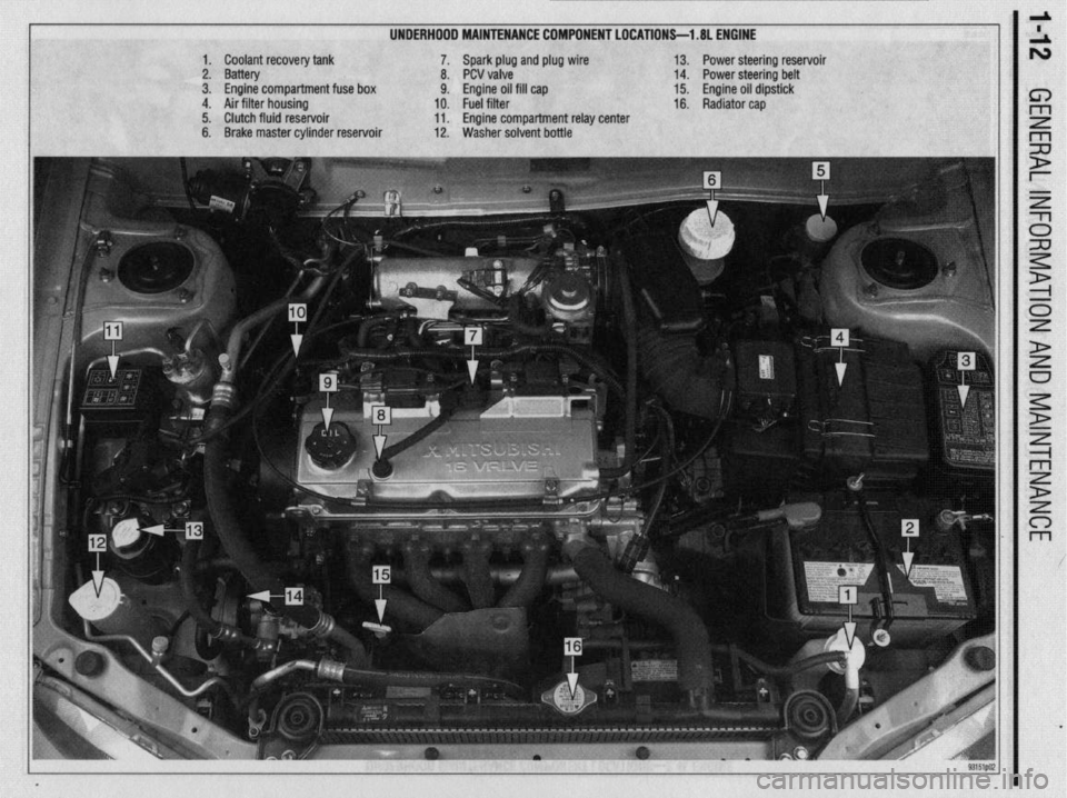
UNDERHOOD MAINTENANCE COMPONENT LOCATIONS-l .8L ENGINE
1. Coolant recovery tank
2. Battery
3. Engine compartment fuse box
4. Air filter housing
5. Clutch fluid reservoir
6. Brake master cylinder reservoir 7. Spark plug and plug wire
8. PCV valve
9. Engine oil fill cap
10. Fuel filter
11. Engine compartment relay center
12. Washer solvent bottle 13. Power steering reservoir
14. Power steering belt
15. Engine oil dipstick
16. Radiator cap
Page 28 of 408
GENERALINFORMATIONAND MAlNTENANdE 1-29
i
*Bug screens which are mounted in front of
the condenser (unless they are original
equipment) are regarded as obstructtons.
l The condensation drain tube expels any water
which accumulates on the bottom of the evaporator
housing into the engine compartment. If this tube is
obstructed, the air conditioning performance can be
restricted and condensation buildup can spill over
onto the vehicle’s floor.
l Make sure the air passage selection lever is
operating correctly. Start the engine and warm it to
normal operating temperature, then make sure the
temperature selection lever is operating correctly.
-w
~1 ELEMENT(REFILL)CARE& REPLACEMENT
SYSTEM INSPECTION
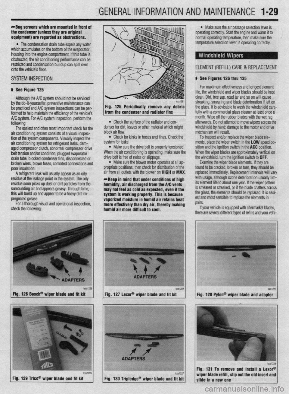
b See Figure 125 b See Figures 126 thru 135
For maximum effectiveness and longest element
Although the A/C system should not be serviced
by the do-it-yourselfer, preventive maintenance can
be practiced and A/C system inspections can be per-
formed to help maintain the efficiency of the vehicle’s
A/C system. For A/C system inspection, perform the
following:
The easiest and often most important check for the
air conditioning system consists of a visual inspec-
tion of the system components. Visually inspect the
air conditioning system for refrigerant leaks, dam-
aged compressor clutch, abnormal compressor drive
belt tension and/or condition, plugged evaporator
drain tube, blocked condenser fins, disconnected or
broken wires, blown fuses, corroded connections and
poor insulation.
A refrigerant leak will usually appear as an oily
residue at the leakage point in the system. The oily
residue soon picks up dust or dirt particles from the
surrounding air and appears greasy. Through time,
this will build up and appear to be a heavy dirt im-
pregnated grease.
For a thorough visual and operational inspection,
check the following: * Check the surface of the radiator and con-
denser for dirt, leaves or other material which might
block air flow.
l Check for kinks in hoses and lines. Check the
system for leaks.
l Make sure the drive belt is properly tensioned.
When the air conditioning is operating, make sure the
drive belt is free of noise or slippage.
l Make sure the blower motor operates at all ap-
propriate positions, then check for distribution of the
air from all outlets with the blower on HIGH or MAX.
*Keep in mind that under conditions of high
humidity, air discharged from the A/C vents
may not feel as cold as expected, even if the
system is working properly. This is because
vaporized moisture in humid air retains heat
more effectively than dry air, thereby making
humid air more difficult to cool.
lifp thp winrkhi&i nnri winor hlarlP~ shmM hP kmt . ..“. .I.” . . * ““I.. “.” I..” ...r”* “.“““” “, ,““,” “” ,~“r~ clean. Dirt, tree sap, road tar and so on will cause
streaking, smearing and blade deterioration if left on
the glass. It is advisable to wash the windshield care-
fully with a commercial glass cleaner at least once a
month. Wipe off the rubber blades with the wet rag
afterwards. Do not attempt to move wipers across the
windshield by hand; damage to the motor and drive
mechanism will result.
To inspect and/or replace the wiper blade ele-
ments, place the wiper switch in the LOW speed po-
sition and the ignition switch in the ACC position.
When the wiper blades are approximately vertical on
the windshield, turn the ignition switch to OFF.
Examine the wiper blade elements. If they are
found to be cracked, broken or torn, they should be
replaced immediately. Replacement intervals will vary
with usage, although ozone deterioration usually lim-
its element life to about one year. If the wiper pattern
is smeared or streaked, or if the blade chatters across
the glass, the elements should be replaced. It is easi-
est and most sensible to replace the elements in
pairs.
If your vehicle is equipped with aftermarket blades,
there are several different types of refills and your vehi-
tcca-23 Fig. 126 Bosch@ wiper blade and fft kit
Fig. 129 T&o* wioer blade and fit kit tCS1224
lW1Z?5 Fig. 127 LexoP wiper blade and fit kit
Fig. 128 Pylon@ wiper blade and adapter
Fig. 131 To remove and install a LexoP
Fig, 130 Tripledge@ wiper blade and fit kit wiper blade refill, slip out the old insert and
slide in a new one
Page 41 of 408
1-42 GENERAL~INFORMATION AND MAINTENANCE
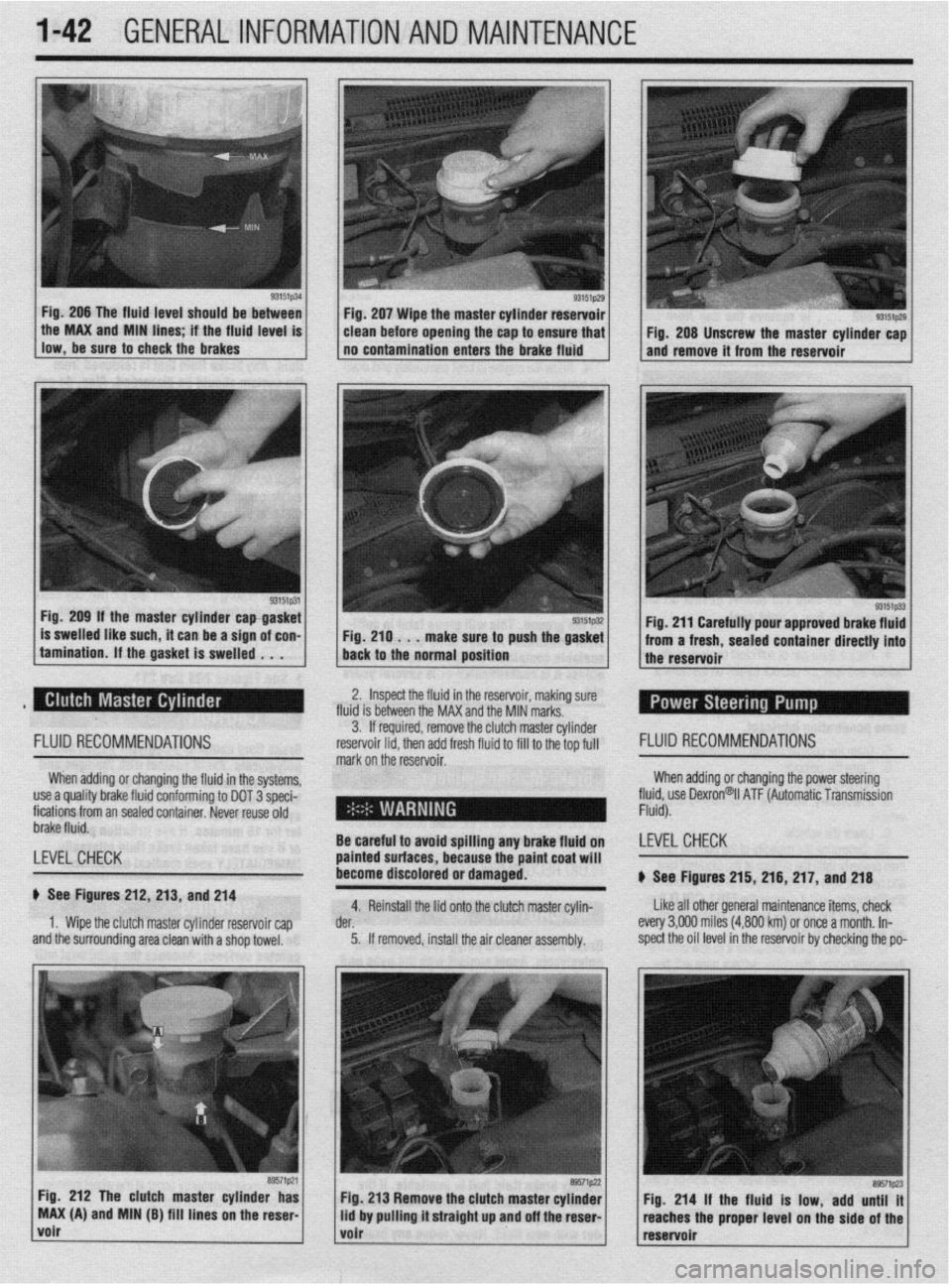
Fig. 206 The fluid level should be between
llow,be*“retoch~ckiebrake~ . the MAX and MIN hnes if the fhud level IS
93151p31 Fig. 209 If the master cylinder capgasket
is swelled like such, it can be a sign of con-
tamination. If the gasket is swelled . . . Fig. 207 Wipe the master cylinder reservoir
clean before opening the cap to ensure that
no contamination enters the brake fluid
Fig. 210 . . .
make sure to push the gasket
back to the normal position
93151p29 I Fig. 208 Unscrew the master cylinder cap
and remove it from the reservoir
Fig. 211 Carefully pour approved brake fluid
from a fresh, sealed container directly into
the reservoir
2. Inspect the fluid in the reservoir, making sure
fluid is between the MAX and the MIN marks.
FLUID RECOMMENDATIONS
When adding or changing the fluid in the systems,
use a quality brake fluid conforming to DOT 3 speci-
fications from an sealed container. Never reuse old
brake fluid.
LEVEL CHECK
b See Figures 212, 213, and 214
1. Wipe the clutch master cylinder reservoir cap
and the surrounding area clean with a shop towel. 3. If required, remove the clut ch master cylinder
reservoir lid. then add fresh fluid I FLUID RECOMMENDATIONS
mark on the’reservoir. to fill to the top full
When adding or changing the power steering
fll$,“” Dexron@il ATF (Automatic Transmission
-
- .
Be careful to avoid sf Billing any brake fluid on LEVELCHECK
painted surfaces, bet
:ause the paint coat will
become discolored or damaged.
b See Figures 215, 216, 217, and 218
4. Reinstall the lid onto the clutch master cylin- Like all other general maintenance items, check
der. every 3,OOfl miles (4,800 km) or once a month. In-
5. If removed, install the air cleaner assembly. spect the oil level in the reservoir by checking the po-
Fig. 212 The clutch master cylinder has
MAX (A) and MIN (B) fill lines on the reser
volr
Page 58 of 408
ENGINE ELECTRICAL 2-11
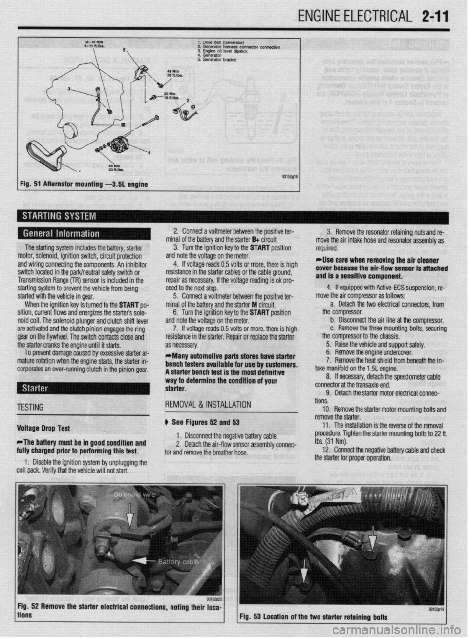
l.unVeMlil(GSflWtWJ
2.Gwwator harness con- connectk,,,
3. Engme OS, level d,pst,&
4 Generator
Fig. 51 Alternator mounting -3.51 engine
The starting system includes the battery, starter
motor, solenoid, ignition switch, circuit protection
and wiring connecting the components. An inhibitor
switch located in the park/neutral safety switch or
Transmission Range (TR) sensor is included in the
starting system to prevent the vehicle from being
started with the vehicle in gear.
When the ignition key is turned to the START po-
sition, current flows and energizes the starters sole-
noid coil. The solenoid plunger and clutch shift lever
are activated and the clutch pinion engages the ring
gear on the flywheel. The switch contacts close and
the starter cranks the engine until it starts.
To prevent damage caused by excessive starter ar-
mature rotation when the engine starts, the starter in-
corporates an over-running clutch in the pinion gear. 2. Connect a voltmeter between the positive ter-
minal of the battery and the starter B+ circuit.
3. Turn the ignition key to the START position
and note the voltage on the meter.
4. If voltage reads 0.5 volts or more, there is high
resistance in the starter cables or the cable ground,
repair as necessary. If the voltage reading is ok pro-
teed to the next step.
5. Connect a voltmeter between the positive ter-
minal of the battery and the starter M circuit,
6. Turn the ignition key to the START position
and note the voltage on the meter.
7. If voltage reads 0.5 volts or more, there is high
resistance in the starter. Repair or replace the starter
as necessary.
*Many automotive parts stores have starter
bench testers available for use by customers.
A starter bench test is the most definitive
way to determine the condition of your
starter. 3. Remove the resonator retaining nuts and re-
move the air intake hose and resonator assembly as
required.
rllse care when removing the air cleaner
cover because the air-flow sensor is attached
and is a sensitive component.
4. If equipped with Active-ECS suspension, re-
move the air compressor as follows:
a. Detach the two electrical connectors, from
the compressor.
b. Disconnect the air line at the compressor.
c. Remove the three mounting bolts, securing
the compressor to the chassis.
5. Raise the vehicle and support safely.
6. Remove the engine undercover.
7. Remove the heat shield from beneath the in-
take manifold on the 1.5L engine.
8. If necessary, detach the speedometer cable
connector at the transaxle end.
9. Detach the starter motor electrical connac-
TESTING
Voltage Drop Test
*The battery must be in good condition and
fully charged prior to performing this test. REMOVAL&INSTALLATION
# See Figures 52 and 53
1. Disconnect the negative battery cable.
2. Detach the air-flow sensor assembly connec-
tor and remove the breather hose.
1. Disable the ignition system by unplugging the
coil pack. Verify that the vehicle will not start. tions.
10. Remove the starter motor mounting bolts and
remove the starter.
11. The installation is the reverse of the removal
procedure. Tighten the starter mounting bolts to 22 ft.
Ibs. (31 Nm).
12. Connect the negative battery cable and check
the starter for proper operation.
9315zp19 Fig. 53 Location of the two starter retaining bolts
Page 116 of 408
ENGINEANDENGINEOVERHAUL 3-55
8. Run a bead of sealer along any seams be-
tween the seal case and block. Install the seal case
with a new gasket.
9. Install the flywheel/driveplate and transaxle.
10. Connect the negative battery cable and check
for leaks.
11. Adjust oil level as necessary.
REMOVAL &INSTALLATION To lnstell:
7. Coat the threads of the driveplate/flywheel re-
taining bolts with thread locking compound.
8. Position the driveplatelflywheel on the crank-
shaft flange.
9. On automatic transaxle equipped models, in-
stall the driveplate adapter.
10. Install and tighten the bolts, in a alternating
star pattern, to the following specifications:
l 1.5L engine: 98 ft. Ibs. (135 Nm) l 1.6L, 2.01 and 2.4L engines: 94-101 ft.
Ibs. (130-140 Nm)
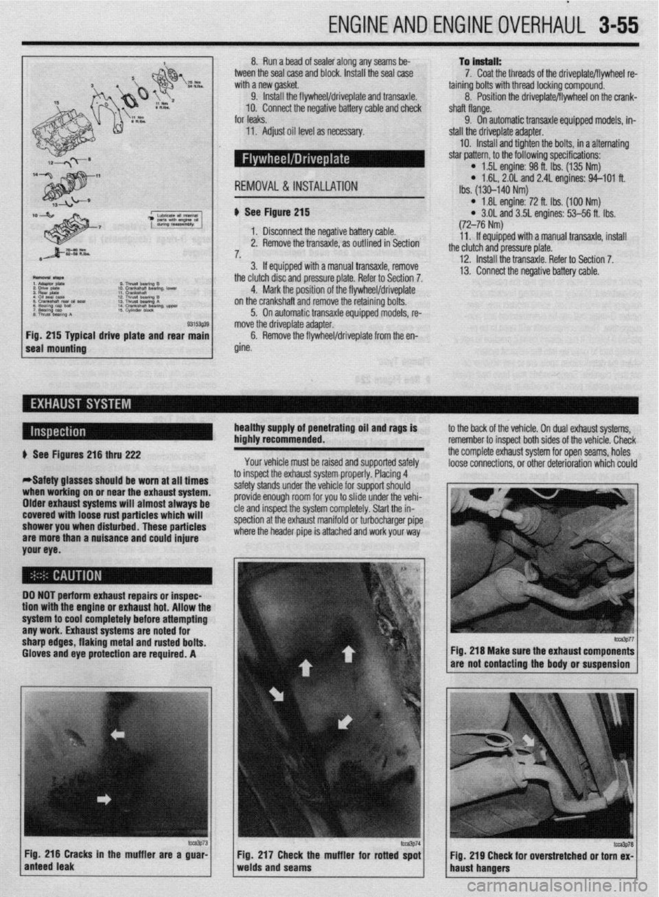
al drive plate and rear b See Figure 215
1. Disconnect the negative battery cable.
2. Remove the transaxle, as outlined in Section
7,
3. If equipped with a manual transaxle, remove
the clutch disc and pressure plate. Refer to Section 7.
4. Mark the position of the flywheel/driveplate
on the crankshaft and remove the retaining bolts.
5. On automatic transaxle equipped models, re-
move the driveplate adapter.
6. Remove the flywheel/driveplate from the en-
gine.
l 1.81 engine: 72 ft. Ibs. (100 Nm) l 3.OL and 3.5L engines: 53-56 ft. Ibs.
(72-76 Nm)
11. If equipped with a manual transaxle, install
the clutch and pressure plate.
12. Install the transaxle. Refer to Section 7.
13. Connect the negative battery cable.
healthy supply of penetrating oil and rags is
highly recommended.
Your vehicle must be raised and supported safely to the back of the vehicle. On dual exhaust systems,
remember to insoect both sides of the vehicle. Check
the complete exhaust system for open seams, holes
loose connections, or other deterioration which could + See Figures 216 thru 222
*Safety glasses should be worn at all times
when working on or near the exhaust system.
Older exhaust systems will almost always be
covered with loose rust particles which will
shower you when disturbed. These particles
are more than a nuisance and could injure
your eye. to inspect the exhaust system properly. Placing 4
safety stands under the vehicle for support should
provide enough room for you to slide under the vehi-
cle and inspect the system completely. Start the in-
spection at the exhaust manifold or turbocharger pipe
where the header pipe is attached and work your way
DO NOT perform exhaust repairs or inspec-
tion wtth the engine or exhaust hot. Allow thr
system to cool completely before attempting
any work. Exhaust systems are noted for
sharp edges, flaking metal and rusted bolts.
Gloves and eye protection are required. A
m3p73 Fig. 216 Cracks in the muffler are a guar-
anteed leak Fig 217 Check the muffler for rotted spot
Fig. 219 Cheek for overstretched or torn ex-
welds and seams
haust hangers
fm3p77 Fig. 216 Make sure the exhaust components
are not contacting the body or suspension
lcca3P78
Page 161 of 408
.
4-18 DRIVEABILITYAND EMISSIONS CONTROLS
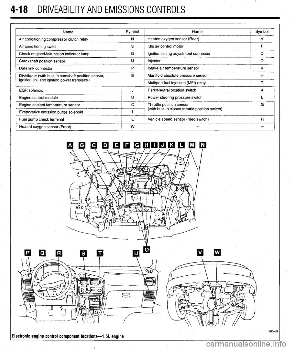
Name ; Symbol Name j Symbol
I
Arr conditioning compressor clutch relay ; N Heated oxygen sensor (Rear)
j ”
Air condrtioning swatch , s 1 Idle air control motor
/ F
/
Check engrne/Malfunction Indicator lamp
/ Q lgnrtion trmrng adjustment connector
j D
Crankshaft position sensor / M Injector
! O
Data link connector
j p Intake air temperature sensor / K
Distributor (wrth bulk-in camshaft position sensor, , B Manifold absolute pressure sensor
ignition coil and rgnrtron power transistor) I 1 H
Multrport fuel in]ectron (MFI) relay
i T
EGR solenord
i J PaWNeutral positron switch j A
Engine control module
I u I Power steering pressure switch
Engine coolant temperature sensor c / Throttle position sensor
Evaporative emission purge solenoid
I I I (with burl&In closed throttle position switch) / L _
/ G
I
I
- Fuel pump check terminal /
I j E i Vehicle speed sensor (reed switch)
/ R
Heated oxygen sensor (Front)
I w I
i -
Ilectronic engine control component locations-l 51 engine 93154go1
Page 163 of 408
4-20 , DRIVEABILITYAND EMISSIONS CONTROLS
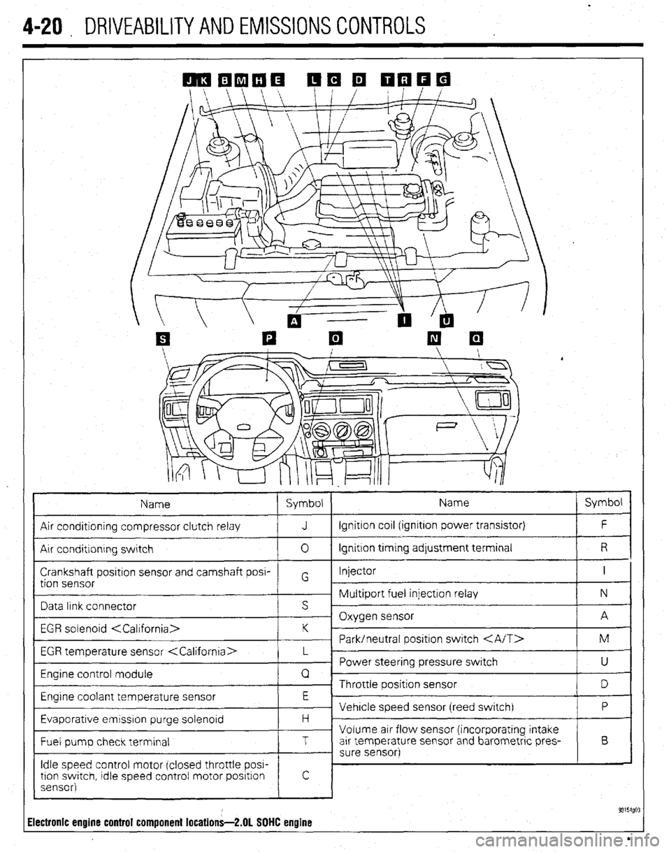
Name Symbol Name Symbol
Air conditioning compressor clutch relay J Ignition coil (ignition power transistor) F
Air conditlonrng switch 0 Ignition trming adjustment terminal R
Crankshaft positron sensor and camshaft posi- Injector I
tion sensor G
~ Multiport fuel injection relay N
Data link connector s ’
- Oxygen sensor A
EGR solenoid
~ Park/neutral positron switch M
EGR temperature sensor
_ Power steering pressure switch
U
Engine control module Q
~ Throttle position sensor
D
Engrne coolant temperature sensor E
Vehicle speed sensor (reed switch) P
Evaporative emrsslon purge solenoid H -
Volume air flow sensor (incorporating intake
Fuel pump check terminal T arr temperature sensor and barometric pres- B
- sure sensor)
Idle speed control motor (closed throttle POW
tron swatch, tdle speed control motor positron
sensor)
! c
93154go: Electronic engine control component locations-2.01 SOHC engine