1900 MITSUBISHI DIAMANTE clutch
[x] Cancel search: clutchPage 281 of 408
7-2 'DRIVETRAIN
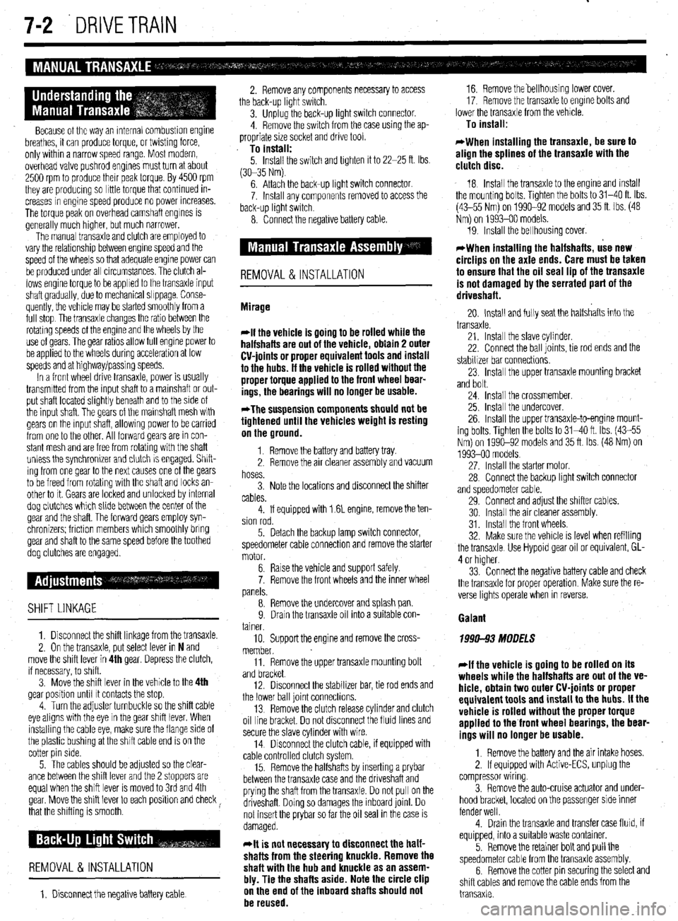
Because of the way an internal combustron engine
breathes, it can produce torque, or twisting force,
only within a narrow speed range. Most modern,
overhead valve pushrod engines must turn at about
2500 rpm to produce their peak torque By 4500 rpm
they are producrng so lrttle torque that contrnued in-
creases in engine speed produce no power increases.
The torque peak on overhead camshaft engines IS
generally much higher, but much narrower.
The manual transaxle and clutch are employed to
vary the relationship between engine speed and the
speed of the wheels so that adequate engine power can
be produced under all crrcumstances. The clutch al-
lows engine torque to be applied to the transaxle input
shaft gradually, due to mechanical slippage. Conse-
quently, the vehicle may be started smoothly from a
full stop The transaxle changes the ratio between the
rotating speeds of the engine and the wheels by the
use of gears. The gear ratios allow full engine power to
be applied to the wheels during acceleration at low
speeds and at highway/passing speeds.
In a front wheel drive transaxle, power is usually
transmitted from the input shaft to a mainshaft or out-
put shaft located slightly beneath and to the side of
the input shaft. The gears of the mainshaft mesh with
gears on the input shaft, allowing power to be carried
from one to the other. All forward gears are in con-
stant mesh and are free from rotating with the shaft
unless the synchronizer and clutch IS engaged. Shaft-
ing from one gear to the next causes one of the gears
to be freed from rotating with the shaft and locks an-
other to it. Gears are locked and unlocked by internal
dog clutches which slide between the center of the
gear and the shaft. The forward gears employ syn-
chronizers; friction members which smoothly bring
gear and shaft to the same speed before the toothed
dog clutches are engaged.
SHIFT LINKAGE
1. Disconnect the shift linkage from the transaxle.
2. On the transaxle, put select lever in N and
move the shift lever in
4th gear. Depress the clutch,
if necessary, to shift.
3. Move the shift lever in the vehicle to the
4th gear position until it contacts the stop.
4. Turn the adjuster turnbuckle so the shift cable
eye aligns with the eye in the gear shift lever. When
installing the cable eye, make sure the flange side of
the plastic bushing at the shift cable end is on the
cotter pin side.
5 The cables should be adjusted so the clear-
ance between the shift lever and the 2 stoppers are
equal when the shift lever IS moved to 3rd and 4th
gear. Move the shift lever to each positron and check i
that the shifting is smooth
REMOVAL &INSTALLATION
1, Disconnect the negative battery cable 2. Remove any components necessary to access
the back-up light switch.
3. Unplug the back-up light switch connector.
4. Remove the switch from the case using the ap-
propriate size socket and drive tool.
To install: 5. Install the switch and tighten it to 22-25 ft. Ibs.
(30-35 Nm).
6. Attach the back-up light switch connector
7. Install any components removed to access the
back-up light switch
8. Connect the negative battery cable.
REMOVAL & INSTALLATION
Mirage
*If the vehicle is going to be roiled while the
halfshafts are out of the vehicle, obtain 2 outer
CV-joints or proper equivalent tools and install
to the hubs. If the vehicle is rolled without the
proper torque applied to the front wheel bear-
ings, the bearings will no longer be usable.
*The suspension components should not be
tightened until the vehicles weight is resting
on the ground.
1. Remove the battery and battery tray.
2. Remove the air cleaner assembly and vacuum
hoses.
3. Note the locations and disconnect the shifter
cables.
4. If equipped with 1.61 engine, remove the ten-
sion rod.
5. Detach the backup lamp switch connector,
speedometer cable connection and remove the starter
motor.
6. Raise the vehicle and support safely.
7. Remove the front wheels and the inner wheel
panels.
8. Remove the undercover and splash pan.
9. Drain the transaxle oil into a suitable con-
tainer
10. Support the engine and remove the cross-
member.
11. Remove the upper transaxle mounting bolt
and bracket.
12 Disconnect the stabilizer bar, tie rod ends and
the lower ball joint connections.
13 Remove the clutch release cylinder and clutch
oil line bracket. Do not disconnect the fluid lines and
secure the slave cylinder with wire.
14 Disconnect the clutch cable, if equipped with
cable controlled clutch system.
15. Remove the halfshafts by inserting a prybar
between the transaxle case and the driveshaft and
prying the shaft from the transaxle. Do not pull on the
driveshaft Doing so damages the inboard joint. Do
not insert the prybar so far the oil seal in the case is
damaged.
*It is not necessary to disconnect the half-
shafts from the steering knuckle. Remove the
shaft with the hub and knuckle as an assem-
bly. Tie the shafts aside. Note the circle clip
on the end of the inboard shafts should not
be reused.
16. Remove the bellhousing lower cover.
17 Remove the transaxle to engine bolts and
lower the transaxle from the vehrcle.
To install:
*When installing the transaxle, be sure to
align the splines of the transaxle with the
clutch disc.
18 Install the transaxle to the engine and install
the mounting bolts. Tighten the bolts to 31-40 ft. Ibs.
(43-55 Nm) on 1990-92 models and 35 ft. Ibs. (48
Nm) on 1993-00 models.
19 Install the bellhousing cover.
*When installing the halfshafts, use new
circlips on the axle ends. Care must be taken
to ensure that the oil seal lip of the transaxle
is not damaged by the serrated part of the
driveshaft.
20. Install and fully seat the halfshafts into the
transaxle.
21. Install the slave cylinder.
22. Connect the ball joints, tie rod ends and the
stabilizer bar connections.
23. Install the upper transaxle mounting bracket
and bolt.
24. Install the crossmember.
25. Install the undercover.
26. Install the upper transaxle-to-engine mount-
ing bolts, Tighten the bolts to 31-40 ft. Ibs. (43-55
Nm) on 199C-92 models and 35 ff. Ibs. (48 Nm) on
1993-00 models.
27. Install the starter motor.
28 Connect the backup light switch connector
and speedometer cable.
29 Connect and adjust the shifter cables.
30 Install the air cleaner assembly.
31. Install the front wheels.
32 Make sure the vehicle is level when refilling
the transaxle Use Hypoid gear oil or equivalent, GL-
4 or higher.
33. Connect the negative battery cable and check
the transaxle for proper operation. Make sure the re-
verse lights operate when in reverse.
Galant
1999-93 MODELS
rlf the vehicle is going to be rolled on its
wheels while the halfshafts are out of the ve-
hicle, obtain two outer CV-joints or proper
equivalent tools and install to the hubs. If the
vehicle is rolled without the proper torque
applied to the front wheel bearings, the bear-
ings will no longer be usable.
1. Remove the battery and the air intake hoses.
2. If equipped with Active-ECS, unplug the
compressor wiring.
3. Remove the auto-cruise actuator and under-
hood bracket, located on the passenger side inner
fender well.
4. Drain the transaxle and transfer case fluid, if
equipped, into a suitable waste container.
5. Remove the retainer bolt and pull the
speedometer cable from the transaxle assembly.
6. Remove the cotter pin securing the select and
shift cables and remove the cable ends from the
transaxle.
Page 282 of 408
DRIVETRAIN 7-3
7. Remove the connection for the clutch release
38. Install the battery.
bolt to 54 ft. Ibs. (73 Nm). Install the front engine roll
cylinder and without disconnecting the hydraulic line,
39. If equipped with Active-ECS, connect the air
stopper through-bolt and hand-tighten. Once the full
and secure it aside.
compressor.
weight of the engine is on the mounts, tighten the
8. Disconnect the backup light switch harness
40. Make sure the vehicle is level when refilling
bolt to 42 ft. Ibs. (57 Nm).
and position aside.
the transaxle. Use Hypoid gear oil or equivalent, GL-
30.
Install the triangular stay bracket and tighten
9. Detach the starter electrical connections, if
4 or higher.
the mounting bolts to 65 ft. Ibs. (88 Nm).
necessary, remove the starter motor and position
41. Check the transaxle and transfer case for
31. Connect the clutch release cylinder.
aside.
proper operation. Make sure the reverse lights come
32. Install the halfshafts, using new circlips on
10. Remove the transaxle mount bracket.
on when in reverse.
the axle ends.
11. Remove the upper transaxle mounting bolts.
12.
Raise the vehicle and support safely on jack-
1!I94-Ol? MODELS
stands.
13. Remove the undercover and the front wheels. 1. Disconnect the negative battery cable and When histalling the axleshaft, keep the in-
14.
Remove the cotter pin and disconnect the tie wait at least 90 seconds before performing any work. board joint straight in relation to the axle, so
rod end from the steering knuckle. 2. Remove the air cleaner and intake hoses. not to damage the oil seal lip of the
15. Remove the self-locking nut from the half- 3. Drain the transaxle into a suitable waste con- transaxle, with the serrated part of the half-
ShaftS. tainer. shaft.
16.
Disconnect the lower arm ball joint from the 4. Remove the cotter pins and clips securing the
steering knuckle. select and shift cables and remove the cable ends 33. Connect the tie rod and ball joints to the steer-
17. Remove the halfshafts from the transaxle. from the transaxle. ing knuckle. Tighten the ball joint self-locking nuts to
18. On AWD models, disconnect the front ex- 5. If equipped with Active-ECS, disconnect the 48 ft. Ibs. (65 Nm). Tighten the tie rod end nut to 21 ft.
haust pipe. air compressor. Ibs. (28 Nm) and secure with a new cotter pin.
19.
On AWD ‘models, remove the transfer case by 6. Disconnect the backup light switch harness 34.
Connect the damper fork to the lower control
removing the attaching bolts, moving the transfer and position aside. arm and tighten the through-bolt to 65 ft. Ibs. (88 Nm).
case to the left and lowering the front side. Remove it 7. Disconnect the speedometer electrical con- 35.
Connect the stabilizer link to the damper fork,
from the rear driveshaft. Be careful of the oil seal. Do nectar, from the transaxle assembly. and tighten the self-locking nut to 29 ft. Ibs. (39 Nm).
not allow the driveshaft to hang; once the front is re- 8. Remove the starter motor and position aside. 36. Install the underpan.
moved from the transfer, tie it up. Cover the transfer 9. Using special tool M2203827 or equivalent, 37. Install wheels and lower vehicle.
case openings to keep out dirt. support the engine assembly. 38. Install the transaxle mount bracket to the
20.
Remove the cover from the transaxle bell- 10. Remove the rear roll stopper mounting transaxle, and tighten the mounting nuts to 32 ft. Ibs.
housing. bracket. (43 Nm).
21. On AWD models, remove the crossmember 11. Remove the transaxle mount bracket. 39. install the rear roll stopper mounting bracket.
and the triangular gusset. 12. Remove the upper transaxle mounting bolts. 40.
Remove the engine support. Tighten the
22. Remove the transaxle lower coupling bolt. It 13. Raise and safely support the vehicle. transaxle mount through-bolt to 51 ft. Ibs. (69 Nm)
is just above the halfshaft opening on FWD or trans- 14. Remove the front wheel assemblies. and tighten the front engine roll stopper through-bolt.
fer case opening on AWD. 15. Remove the right hand undercover. 41. Install the upper transaxle mounting bolts
23.
Support the weight of the engine from above 16. Remove the cotter pin and disconnect the tie and tighten to 35 ft. Ibs. (48 Nm).
(chain hoist). Support the transaxle using a transmis- rod end, from the steering knuckle. 42. Install the starter motor.
sion jack and remove the remaining lower mounting 17. Disconnect the stabilizer bar link, from the 43. Attach the backup light switch and the
bolts. damper fork. speedometer connector.
24. On turbocharged vehicle, be careful not to 18. Disconnect the damper fork, from the lateral 44.
Connect the select and shift cables and install
damage the lower radiator hose with the transaxle lower control arm. new cotter pins.
housing during removal. Wrap tape on both the lower 19. Disconnect the later lower arm, and the com- 45.
Install the air cleaner and the air intake hose.
hose and the transaxle housing to prevent damage. pression arm, lower ball joints, from the steering 46. Connect the negative battery cable.
Move the transaxle assembly to the right and care- knuckle. 47. Make sure the vehicle is level, and refill the
fully lower it from the vehicle. 20. Pry the halfshafts from the transaxle, and se- transaxle.
To install: cure aside. 48.
Check the transaxle for proper operation. Make
25.
Install the transaxle to the engine and install 21. Remove the connection for the clutch release sure the reverse lights come on when in reverse.
the mounting bolts, Tighten the bolts to 35 ft. Ibs. (48 cylinder and without disconnecting the hydraulic line,
Nm). Install the transaxle lower coupling bolt. secure aside.
26.
Install the underpan, crossmember and the 22. Remove the cover from the transaxle bell-
triangular gusset. housing.
27.
Install the transfer case on AWD models and 23. Remove the engine front roll stopper REMOVAL&INSTALLATION
connect the exhaust pipe. through-bolt.
28.
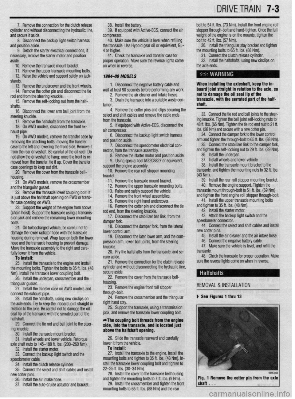
Install the halfshafts, using new circlips on 24. Remove the crossmember and the triangular ) See Figures 1 thru 13
the axle ends. Try to keep the inboard joint straight in right hand stay.
relation to the axle. Be careful not to damage the oil 25. Support the transaxle, using a transmission
seal lip of the transaxle with the serrated part of the jack, and remove the transaxle lower coupling bolt.
halfshaft.
29. Connect the tie rod and ball joint to the steer- *The coupling bolt threads from the englne
side, into the transaxle, and is located just
ing knuckle.
30. Install the transaxle mount bracket. above the halfshaft opening.
31. Install wheels and lower vehicle. Retorque 26. Slide the transaxle rearward and carefully
axle shaft nuts to 145-188 ft. Ibs. (200-260 Nm). lower it from the vehicle.
32. Install the starter motor. To install:
33. Connect the backup light switch and the 27. Install the transaxle to the engine. Install the
speedometer cable. mounting bolts and tighten to 35 ft. Ibs. (48 Nm). In-
34. Install the clutch release cylinder. stall the transaxle lower coupling bolt and tighten to
35.
Connect the select and shift cables and install 22-25 ft. Ibs. (30-34 Nm).
new cotter pins. 28. Install the cover to the transaxle bellhousing
36. Install the air intake hose. and tighten the mounting bolts to 7 ft. Ibs. (9 Nm).
37. Install the auto-cruise actuator and bracket. 29. Install the crossmember and tighten the front
mounting bolts to 65 ft. Ibs. (88 Nm) and the rear
Page 286 of 408
DRlVETRilN 7-7
bansaxle. When the pedal is pushed inward, the disc
and plate separate (the clutch is disenqaqed) discon-
necti
M no the enoine from the transaxie.- .
The clutch driven disc mav comam asoestos.
Galant and Mirage
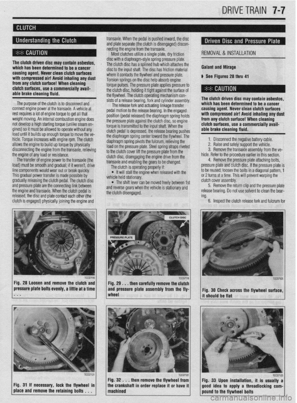
b See Figures 28 thru 41 ost clutches utilize a single plate, dry friction REMOVAL &INSTALLATION
.* * _ disc with a diaphragm-style spring pressure plate.
which has been determined to be a cancer ’ The clutch disc has a splined hub which attaches the
causing agent. Never clean clutch surfaces disc to the input shaft. The disc has friction material
with compressed air! Avoid inhaling any dust where it contacts the flywheel and pressure plate.
from any clutch surface! When cleaning Torsion springs on the disc help absorb engine
clutch surfaces, use a commercially avail- torque pulses. The pressure plate applies pressure to
able brake cleaning fluid. the clutch disc, holding it tight againstthe surface of
the flywheel. The clutch operating mechanism con-
sists of a release bearing, fork and cylinder assembly. The clutch driven disc may contain asbestos,
The purpose of the clutch is to disconnect and
The release fork and actuating linkage transfer which has been determined to be a cancer
connect engine power at the tram&e. A vehicle at
pedal motion to the release bearing. In the engaged causing agent. Never clean clutch surfaces
rest requires a lot of engine torque to get all that
weight moving. An internal combustion engine does position (pedal released) the diaphragm spring holds with compressed air! Avoid inhaling any dust
the pressure plate against the clutch disc, so engine from any clutch surface! When cleaning
not develop a high starting torque (unlike steam en-
torque is transmitted to the input shaft. When the clutch surfaces, use a commercially avail-
gines) so it must be allowed to operate without any
clutch pedal is depressed, the release bearing pushes able brake cleaning fluid.
load until it builds up enough torque to move the ve-
hicle. Torque increases with engine rpm. The clutch the diaphragm spring center toward the flywheel. The
diaphragm spring pivots the fulcrum, relieving the 1. Disconnect the negative battery cable.
allows the engine to build up torque by physically
disconnecting the engine from the transaxle, relieving load on the pressure plate. Steel spring straps riveted 2. Raise and safely support the vehicle.
the engine of any load or resistance. to the clutch cover lift the pn--“-- -I-‘^ I--- ‘!-- 3. Remove the transaxle assemblv from the ve-
The transfer of engine power to the transaxle (the clutch disc, disengaging the Gllyl,lo UllVc IIVIII II1c
4. Remove the oressure elate attachina bolts.
load) must be smooth and gradual; if it weren’t, drive transaxle and enabling the gc”-- +,, h,n -‘----’
line components would wear out or break quickly. The clutch is operating pryV’uV,J ,,.
l to be reused, loosen the bolts in a diagonal pattern 1
This gradual power transfer is made possible by It will stall the engine when released with the
vehicle held stationary. or 2 turns at a time. This will prevent warping the
gradually releasing the clutch pedal. The clutch disc
l The shift lever can be moved freely between 1st clutch cover assembly.
and pressure plate are the connecting link between
and reverse gears when the vehicle is stationary and 5. Remove the return clip and the pressure plate
the engine and transaxle. When the clutch pedal is
the clutch disengaged. release bearing. Do not use solvent to clean the bear-
released, the disc and plate contact each other (the ing.
clutch is engaged) ohvsicallv ioinina the enaine and 6. lnsoect the clutch release fork and fulcrum for hicle. Refer to the procedure earlier in this section.
pressure plate and clutch disc. If the pressure plate is
TCCS7118 Fig. 28 Loosen and remove the clutch and
. . . then carefully remove the clutch
essure plate bolts evenly, a little at a time
1~~~~~ -1 [it&ouldbeflat and pressure plate assembly from the fly
- ‘(
1 .
Fig. 33 Upon installation, it is usually a 7 1 / F@%!,d . then remove the flywhee;;:! 1 1 pound’to the flywheel bolts . Tccs7’z3~
Ftg. 31 If necessary, lock the flywheel III
the crankshaft m order replace d or have d
place and remove the retaining bolts . . . good Idea to apply a threadlockmg com-
Page 287 of 408
7-8 DRIVETRAIN
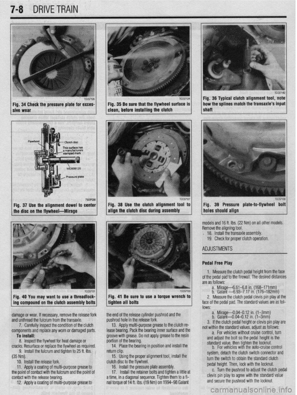
/ sive Wear TCCS7124 1 Fig 34 Check the pressure plate for exces- TCCS7126 j / . Fig 38 Be sure that the flywheel surface is
clean, before installing the clutch
Fig. 38 Use the clutch alignment tool to
align the
clutch disc during assembly
Fig. 40 You may want to use a threadlock- Fig, 41 Be sure to use a torque wrench to
ing compound on the clutch assembly bolts
tighten all bolts
damage or wear. If necessary, remove the release fork the end of the release cylinder pushrod and the
and unthread the fulcrum from the transaxle. pushrod hole in the release fork.
7. Carefully inspect the condition of the clutch 13. Apply multi-purpose grease to the clutch re-
components and replace any worn or damaged parts.
lease bearing. Pack the bearing inner surface and the r Fig. 36 Typical clutch alignment tool, note
shaft ,,, 1 how the splines match the transaxle’s input
TCCS7130 Fig. 39 Pressure plate-to-flywheel bolt
holes should align
nodels and 16 ft. Ibs. (22 Nm) on all other models.
3emove the aligning tool.
. 18. Install the transaxle assembly.
19. Check for proper clutch operation.
4DJUSTMENTS
Pedal Free Play
1. Measure the clutch pedal height from the face
of the pedal pad to the firewall. The desired distances
are as follows:
a. Mirage--&6148 in. (168-171mm)
b. Galant -6.93-7.17 in. (176182mm)
2. Measure the clutch pedal clevis pin play at the
ace of the pedal pad. The standard values are as fol-
DWS: a. Mirage--0.04--0.12 in. (l-3mm)
b. Galant4.04-0.12 in. (l-3mm)
3. If the clutch pedal height or clevis pin play are
rot within the standard values, adjust as follows:
Page 288 of 408
DRIVETRAIN 7-9
*When adjusting the clutch pedal height or
the clutch pedal clevis pin play, be careful
not to push the pushrod toward the master
cylinder.
d. Check that when the clutch pedal is de-
pressed all the way, the interlock switch switches
over from ON to OFF.
ADJUSTMENT
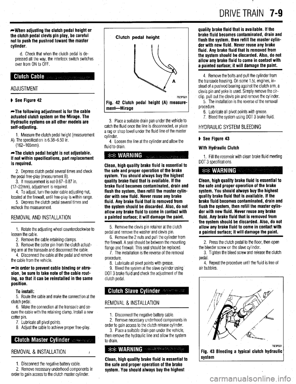
# See Figure 42
*The following adjustment is for the cable
actuated clutch system on the Mirage. The
Hydraulic systems on all other models are
self-adjusting.
1. Measure the clutch pedal height (measurement
A). The specificatron is 6.38-6.50 in.
(162-165mm).
*The clutch pedal height is not adjustable.
If not within specifications, part replacement
is required.
2. Depress clutch pedal several times and check
the pedal free-play (measurement B).
3. If measurement is not 0.67-0.87 in.
(17-22mm), adjustment is required.
4. To adjust, turn the outer cable adjusting nut,
located at the firewall, until free-play is within range.
5. Depress the clutch pedal several times and
recheck the measurement.
REMOVALANDINSTALLATION
1. Rotate the adjusting wheel counterclockwise to
loosen the cable.
2. Remove the cable retaining clamps.
3. Remove the cotter pin from the clutch actuat-
ing arm at the transaxle and disconnect the cable.
4. Disconnect the cable at the pedal and remove
the cable from the vehicle.
rln order to prevent cable binding or abra-
sion, be sure to take note of the cable rout-
ing, so that it can be reinstalled in the same
position.
To install:
5. Route the cable and make the connection at the
clutch pedal.
6. Make the connection at the transaxle and se-
cure the cable with the retaining clamp. Install a new
cotter pin.
7. Lubricate all pivot points.
8 Adjust the cable to achieve proper free-play.
REMOVAL &INSTALLATION
I
1. Disconnect the negative battery cable.
2. Remove necessary underhood components in
order to gain access to the clutch master cylinder.
Clutch pedal height
Fig. 42 Clutch pedal height (A) measure-
ment-Mirage
7923PGDl
3. Place a suitable drain pan under the vehicle to
catch the fluid once the line IS drsconnected, or place
a rag or shop towel under the fluid line of the master
cylinder.
4. Loosen the line at the cylinder and allow the
fluid to drain.
Clean, high quality brake fluid is essential to
the safe and proper operation of the brake
system. You should always buy the highest
quality brake fluid that is available. If the
brake fluid becomes contaminated, drain and
flush the system, then refill the master cylin-
der with new fluid. Never reuse any brake
fluid. Any brake fluid that is removed from
the system should be discarded. Also, do not
allow any brake fluid to come in contact with
a oainted surface; it will damage the paint.
5. Remove the clevis pin retainer at the clutch
pedal and remove the washer and clevis pm.
6. Remove the 2 nuts and pull the cylinder from
the firewall. A seal should be between the mounting
flange and firewall. This seal should be replaced.
7. The installation is the reverse of the removal
procedure.
8. Lubricate all pivot points with grease.
9. Bleed the system at the slave cylinder using
DOT 3 brake fluid and check the adjustment of the
clutch pedal.
REMOVAL &INSTALLATION
1. Disconnect the negative battery cable
2. Remove necessary underhood components in
order to gain access to the clutch release cylinder.
3. Place a suitable drain pan under the vehicle,
then remove the hydraulic line and allow the system
to drain.
Clean, high quality brake fluid is essential to
the safe and proper operation of the brake
system. You should always buy the highest quality brake fluid that is available. If the
brake fluid becomes contaminated, drain and
flush the system, then refill the master cylin-
der with new fluid. Never reuse any brake
fluid. Any brake fluid that is removed from
the system should be discarded. Also, do not
allow any brake fluid to come in contact with
a uainted surface; it will damage the paint.
4. Remove the bolts and pull the cylinder from
the transaxle housing. On some 1.5L engines, in-
stead of a pushrod bearing against the clutch arm, a
clevis pin and yoke is used. Simply remove the cir-
clip, pull out the clevis pin and remove the cylinder.
5. The installation IS the reverse of the removal
procedure.
6. Lubricate all pivot points with grease.
7. Bleed the system using DOT 3 brake fluid.
HYDRAULIC SYSTEM BLEEDING
) See Figure 43
With Hydraulic Clutch
1, Fill the reservoir with clean brake fluid meeting
DOT 3 specificatrons.
Clean, high quality brake fluid is essential to
the safe and proper operation of the brake
system. You should always buy the highest
quality brake fluid that is available. If the
brake fluid becomes contaminated, drain and
flush the system, then refill the master cylin-
der with new fluid. Never reuse any brake
fluid. Any brake fluid that is removed from
the system should be discarded. Also, do not
allow any brake fluid to come in contact with
a painted surface; it will damage the paint.
2. Press the clutch pedal to the floor, then open
the bleeder screw on the slave cvlinder.
3. Tighten the bleed screw and release the clutch
pedal.
4. Repeat the procedure until the fluid is free of
air bubbles.
7923PG91 Fig. 43 Bleeding a typical clutch hydraulic
system
Page 295 of 408
.
7-16 DRIVETRAIN
11. Using puller, remove the oil seal and inner 18. While holding the rear axle shaft in positron
bearing from the trailing arm. using holding fixture tool MB9g67-01 or equivalent,
12. Inspect the companion flange and axle shaft tighten a new self-locking nut to 159 ft. Ibs. (220 Nm).
for wear or damage. Inspect the dust cover for defor- 19. Install the drive shaft nuts, washers and bolts.
mation or damage. Inspect the bearings for burning Tighten to 40-47 ft. Ibs. (55-65 Nm).
or declaration. Replace components as required 20. Install the rear brake disc, caliper assembly
To install: and parking brake.
13. Using the proper driver, press fit the inner
bearing onto the trailing arm. Press fit the oil seal
onto the trailing arm with the depression in the oil
seal facing upward, and until it contacts the shoulder
on the inner arm. 21. Install the tire and wheel assembly and lower
the vehrcle. Check the parking brake stroke and ad-
just as required.
22. Before moving the vehicle, pump the brakes
until a firm pedal is achieved.
*When tapping the oil seal in, use a plastic
hammer to lightly tap the top and circumfer-
ence of the seal installation tool, press fitting
gradually and evenly.
14. Press fit the dust covers onto the axle until it
contacts the axle shaft shoulder. Install the innermost
cover so the deDression is facino
UDWard.
REMOVAL &INSTALLATION
1. Raise the vehicle and support safely.
2. Matchmark the driveshaft and comoanion . ,
*When tapping the oil seal in, use a plastic
hammer to lightly tap the top and circumfer-
ence of the seal installation tool, press fitting
gradually and evenly. flange and remove the shaft. Don’t let it hang from the
transaxle. Tie It up to the underbody.
3. Hold the companion flange stationary and re-
move the large self-locking nut in the center of the
comoanion flanoe.
15. Apply multi-purpose grease around the entire 4: Using a Gller, remove the flange. Pry the old
circumference of the Inner side of the outer bearing seal out.
seal lip. Press fit the outer bearing to the axle shaft so
To install: that the bearrng seal lip surface is facing towards the 5. Apply a thin coat of multi-purpose grease to the
axle shaft flange. seal lip and the companion flange seal contacting sur-
16. Press fit the rear rotor to the axle shaft with face. Install the new seal with an appropriate driver.
the rear rotor groove surface towards the axle shaft 6. Install the companion flange. Install a new lock-
flange. nut and torque to 116-159 fl Ibs. (157-220 Nm). The
17. Install the rear axle shaft to the trailing arm rotation torque of the drive pinion should be about 4
temporarily. Install the companion flange to the rear inch Ibs. for new or reused, oiled bearings
axle shaft, then install a new self-locking nut. 7. Install the driveshaft.
REMOVAL &INSTALLATION
1. Raise the vehicle and support safely.
2. Drain the differential gear oil and remove the
center exhaust pipe.
3. Matchmark and remove the rear driveshaft.
4. Remove the rear halfshafts.
5. Remove the center exhaust pipe and muffler
assembly, as required.
6. Remove or disconnect the 4 wheel steering
oil pump.
7. The large mounting bolts that hold the differ-
ential carrier support plate to the underbody may use
self-locking nuts. Before removing them, support the
rear axle assembly in the middle with a transaxle
jack. Remove the nuts, then remove the support
plate(s) and the square dynamic damper from the rear
of the carrier.
8 Lower the differential carrier and remove from
the vehicle.
To install: 9. Raise the rear differential carrier into position
and install support member bolts. Install new lock-
nuts on all support bolts.
10. Install the 4 wheel steering oil pump.
11. Install new circlips on both rear driveshafts
and install.
12. Install the propeller shaft.
13. Install the center exhaust pipe and muffler.
14. Lower the vehicle.
15. With the vehicle level, fill the rear differential.
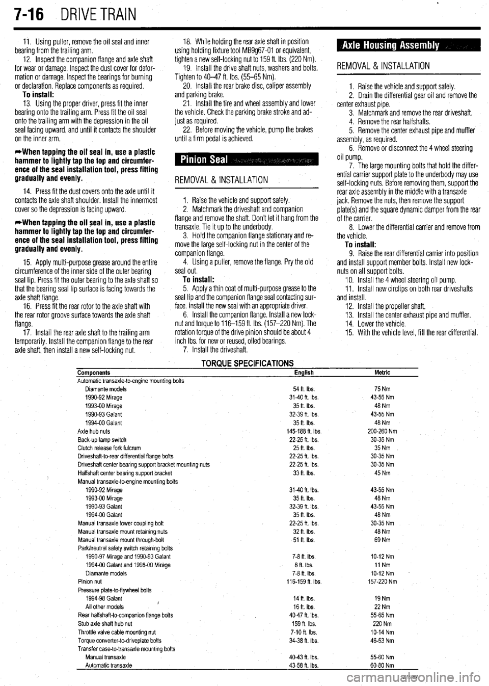
TORQUE SPECIFICATIONS Components English
Automatic Vansaxle-toengme mountrng bolts
Diamante models 54ft Ibs.
1990-92 Mrrage 3140ft Ibs.
199390 Mrrage 35ft Ibs.
1990-93 Galant 32-39 ft Ibs.
199400 Galant 35ft Ibs.
Axle hub nuts 145-188 ft tbs
Back-up lamp swatch 22-25 ft Ibs.
Clutch release fork fulcrum 25ft Ibs
Driveshaft-to-rear drfferentral flange bolts 22-25 fl lb?..
Driveshaft center bearrng support bracket mountrng nuts 22-25 fl. Ibs.
Halfshaft center bearing support bracket 33ft Ibs.
Manual transaxle-toengrne mountrng bolts
1990-92 Mtrage 3140 ft. Ibs.
1993-00 Mrrage 35 ft. Ibs.
1990-93 Galant 32-39 fl I bs.
199400 Galant 35ft Ibs.
Manual transaxle lower coupling bolt 22-25ft Ibs
Manual transaxle mount retaining nuts 32ft Ibs.
Manual transaxle mount through-bolt 51 R Ibs.
Park/neutral safety swatch retainrng bolts
1990-97 Mrrage and 1990-93 Galant 76 ft. Ibs
1994-00 Galant and 199600 Mirage afl Ibs
Dramante models
78 fl. Ibs
Pinion nut
116-159fl lb?..
Pressure plate-to-flywheel bolts
1994-98 Galant
14ft Ibs.
/
All other models 16ft Ibs.
Rear halfshaft-tocompanron flange bolts 4047ft Ibs.
Stub axle shaft hub nut 159n Ibs.
Throttle valve cable mounting nut 7-10 ft. Ibs.
Torque converter-todnveplate bolts 34-38 n. ibs
Transfer case-to-transaxle mounttng bolts
Manual transaxle
4043n Ibs.
Automatic transaxle
43-58 ft. Ibs. Metric
75 Nm
43-55 Nm
48 Nm
43-55 Nm
48 Nm
200-260 Nm
30-35 Nm
35 Nm
30-35 Nm
30-35 Nm
45 Nm
43-55 Nm
48 Nm
43-55 Nm
48 Nm
30-35 Nm
40 Nm
69 Nm
IO-12 Nm
11 Nm
IO-12 Nm
157-220 Nm
19 Nm
22 Nm
5565 Nm
220 Nm
lo-14 Nm
46-53 Nm
5560 Nm
60-80 Nm
93157co1
Page 340 of 408
9-4 BRAKES
Fig 8 Unfasten the master cylinder-to-
power booster retaining nuts . . . F57g’6~ Fig. 9 . . . then remove the master cylinder
assembly from the vehicle Fig. 10 The brake booster pushrod and prf-
mary piston clearance (A) must be adjusted
1. Disconnect the negative battery cable.
2. Remove the master cylinder reservoir cap,
then use a clean turkey baster or equivalent to siphon
out as much fluid as possible and place in a suitable
container. Install the cap.
Brake fluid contains polyglycol ethers and
polyglycols. Avoid contact with the eyes and
wash your hands thoroughly after handling
brake fluid. If you do get brake fluid in your
eyes, flush your eyes with clean, running wa-
ter for 15 minutes. If eye irritation persists,
or if you have taken brake fluid internally,
IMMEDIATELY seek medical assistance.
3. Disconnect and plug the lines from the brake
master cylinder reservoir.
4. Detach the fluid level sensor connector, un-
fasten the retainers, then remove the master cylinder
reservoir.
5. For vehicles equipped with manual transaxle,
remove the clutch master cylinder reservoir bracket.
6. Disconnect and plug the brake lines from the
master cylinder.
7. Unfasten the master cylinder-to-power
booster retainino nuts, then remove the master cvlin- ante value will become 0.004-0.012 in.
(0.1-0.3mm).
9. install the master cylinder to the brake
booster, then install the retaining nuts. Tighten the
nuts to 7 ft. Ibs. (10 Nm).
10. Install the master cylinder reservoir, securing
the retainers.
11. Attach the fluid level sensor connector, then
unplug and connect the fluid lines to the reservoir.
12. The remainder of installation is the reverse of
the removal procedure. Fill the reservoir with the
proper type and amount of DOT 3 brake fluid from a
fresh, sealed container.
I l
Clean, high quality brake fluid is essential to
the safe and proper operation of the brake
system. You should always buy the highest
quality brake fluid that is available. If the
brake fluid becomes contaminated, drain and
flush the system, then refill the master cylin-
der with new fluid. Never reuse any brake
fluid. Any brake fluid that is removed from
the system should be discarded. Also, do not
allow any brake fluid to come in contact with
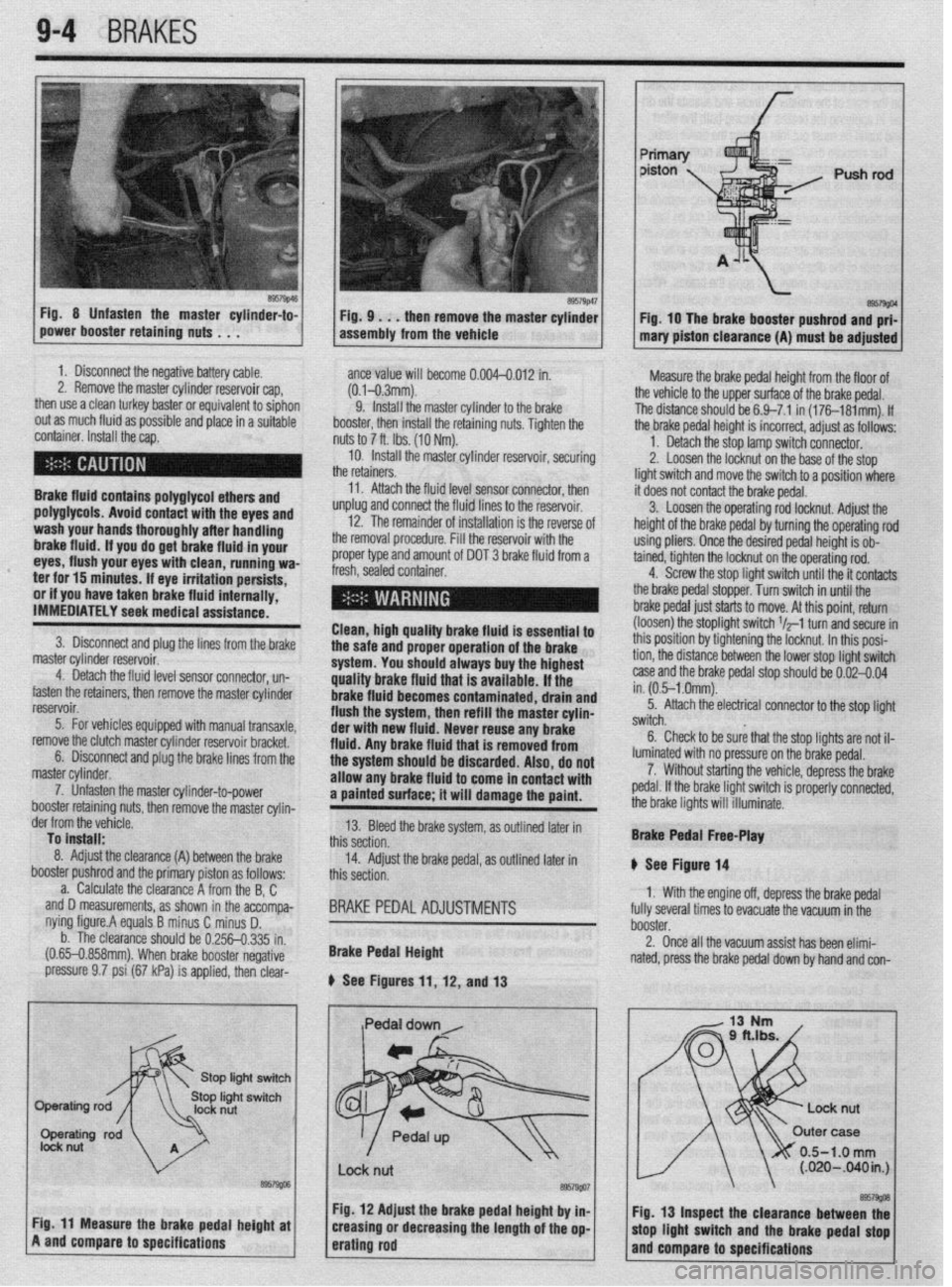
a painted surface; it will damage the paint. Measure the brake pedal height from the floor of
the vehicle to the upper surface of the brake pedal.
The distance should be 6.9-7.1 in (176181mm). If
the brake pedal height is incorrect, adjust as follows:
1. Detach the stop lamp switch connector.
2. Loosen the locknut on the base of the stop
light switch and move the switch to a position where
it does not contact the brake pedal.
3. Loosen the operating rod locknut. Adjust the
height of the brake pedal by turning the operating rod
using pliers. Once the desired pedal height is ob-
tained, tighten the locknut on the operating rod.
4. Screw the stop light switch until the it contacts
the brake pedal stopper. Turn switch in until the
brake pedal just starts to move. At this point, return
(loosen) the stoplight switch $-1 turn and secure in
this position by tightening the locknut. In this posi-
tion, the distance between the lower stop light switch
case and the brake pedal stop should be 0.02-0.04
in. (0.5-l .Omm).
5. Attach the electrical connector to the stop light
switch.
6. Check to be sure that the stop lights are not il-
luminated with no pressure on the brake pedal.
7. Without starting the vehicle, depress the brake
pedal. If the brake light switch is properly connected,
the brake lights will illuminate.
der from the vefiicle.
To install:
8. Adjust the clearance (A)
booster pushrod ant
a. Calculate tl -,
between the brake
I the primary piston as follows:
le clearance A from the B, C
accompa-
i D.
I.335 in.
negative and D measurements, as shown in the
nying figure.A equals B minus C minus
b. The clearance should be 0.256-t
(0.65-0.858mm). When brake booster I
pressure 9.7 psi (67 kPa) is applied, then clear- 13. Bleed the brake system, as outlined later in
this section.
14. Adjust the brake pedal, as outlined later in
this section.
BRAKE PEDAL ADJUSTMENTS
Brake Pedal Height
b See Figures 11, 12, and 13 Brake Pedal Free-Play
II See Figure 14
1. With the engine off, depress the brake pedal
fully several times to evacuate the vacuum in the
booster.
2. Once all the vacuum assist has been elimi-
nated, press the brake pedal down by hand and con-
/
0.5-1.0 mm (.020-B40in.J I
I
I I
Fig. 12 Adjust the brake pedal height by in- I I.
@57w
Cir 44 “a*., .._^ *I.- 9.--l,- ---I-* L-@-L. -I Fig. 13 Inspect the clearance between thf . . - _-.L -*.a- - . . * _ . . . . ._ . rly. I I rnca~urc we urime peoai nefgnr ar
A and compare to specifications creasmg or aecreasing the lengrn or me op-
erating rod mop llgnt WItCh arm the brake pedal stop
and compare to specifications
Page 383 of 408

TROUBLESHOOTING INDEX 11-2
SECTION 1: ENGINE 11-2
SECTION 2: DRIVE TRAIN
11-3
SECTION 3:BRAKESYSTEM 11-3
SECTION 4:WHEELS,TIRES, STEERING,
AND SUSPENSION II-4
SECTION 5: ELECTRICAL
ACCESSORIES II-4
SECTION 6:lNSTRUMENTSAND
GAUGES II-5
SECTION 7:CLlMATE CONTROL II-5
DIAGNOSTIC PROCEDURES II-6
SECTION 1: ENGINE II-6
ENGINE STARTING PROBLEMS II-6
ENGINE RUNNING CONDITIONS II-7
ENGINE NOISES,ODORSAND
VIBRATIONS II-8
ENGINE ELECTRICALSYSTEM 11-8
ENGINE COOLING SYSTEM II-8
ENGINE EXHAUSTSYSTEM II-9
SECTION 2: DRIVE TRAIN
II-9
AUTOMATIC TRANSMISSION II-9
MANUALTRANSMISSION II-10
CLUTCH II-10
DIFFERENTIAL AND FINAL
DRIVE II-10
TRANSFER ASSEMBLY II-10
DRIVESHAFT II-10
AXLES II-II
OTHER DRIVE TRAIN
CONDITIONS II-II
SECTION 3:BRAKE SYSTEM II-II
BRAKESYSTEM
TROUBLESHOOTING II-II
SECTION 4:WHEELS, TIRES, STEERING
AND SUSPENSION II-12
WHEELSAND WHEEL
BEARINGS II-12
TIRES II-12
STEERING II-12
SUSPENSION II-12
DRIVING NOISES AND
VIBRATIONS II-13
SECTION 5:ELECTRlCAL
ACCESSORIES II-13 -
HEADLIGHTS II-13
TAIL, RUNNING AND SIDE MARKER
LIGHTS II-13
INTERIOR LIGHTS II-14
BRAKE LIGHTS II-14
WARNING LIGHTS II-14
TURN SlGNALAND4-WAYHAZARD
LIGHTS II-15
WINDSHIELD WIPERS II-15
SECTION 6:lNSTRUMENTSAND
GAUGUES II-15
I
SPEEDOMETER(CABLE
OPERATED) II-15
SPEEDOMETER(ELECTRONICALLY
OPERATED) II-16
FUEL,TEMPERATUREAkJD OIL
PRESSURE GAUGES II-16 SECTION 7:CLlMATECON
AIR CONDITIONER ll-
HEATER II-16 TR(
-16 IL II-16