1900 MITSUBISHI DIAMANTE clutch
[x] Cancel search: clutchPage 165 of 408
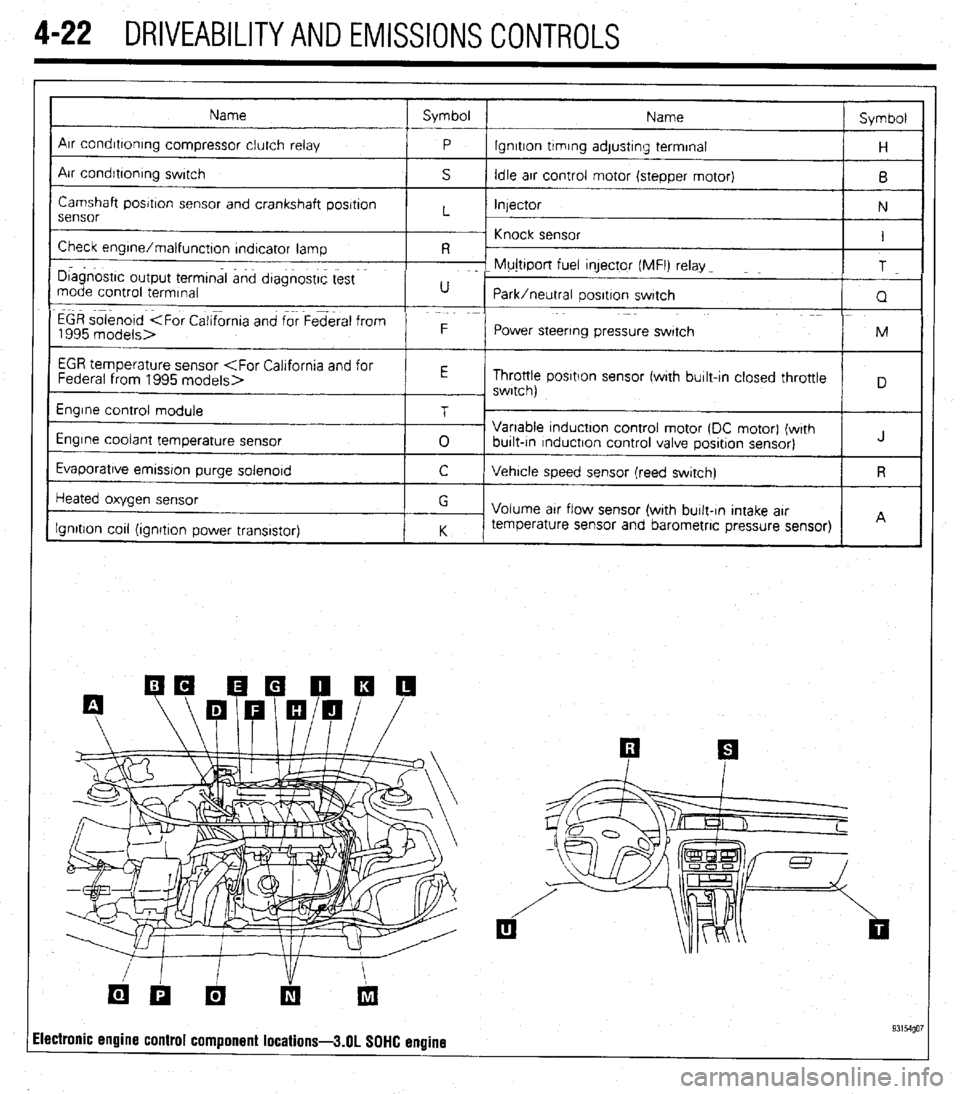
4-22 DRIVEABILITYAND EMISSIONS CONTROLS
Name Symbol
Name Symbol
I
Arr condrttontng compressor clutch relay
P lgnrtton trmrng adjustrng terminal
H
Air condrbonrng swrtch
S Idle arr control motor (stepper motor)
B
Camshaft posrtron sensor and crankshaft posrtron
Injector
N
sensor L
~ Knock sensor
Check engrne/malfunctton rndtcator lamp I
R -
I D~agnostrc output termtnal and dtagnostrc test F- Mujttport fuel qector (MFI) relay _
T
mode control termrnal U
Park/neutral oosrtron swatch
Q
EGR solenoid
1995 models> F
Power steering pressure swatch M
I
EGR temperature sensor
Throttle posrtlon sensor fwrth burlt-In closed throttle
, swrtch)
Engrne control module
Engine coolant temperature sensor
Evaporatrve emrssron purge solenord T
0 Variable tnductton control motor (DC motor) (wrth
burlt-tn rnductron control valve posrtron sensor) J
C Vehrcle speed sensor (reed swatch) R
Heated oxygen sensor
Ignition cot1 (ionrtron Dower transistor) G
Volume arr flow sensor (with burlt-In Intake arr
K temperature sensor and barometric pressure sensor)
I I A
ilectronic engine control component locations-3.01 SOHC engine 93154go7
Page 167 of 408
.
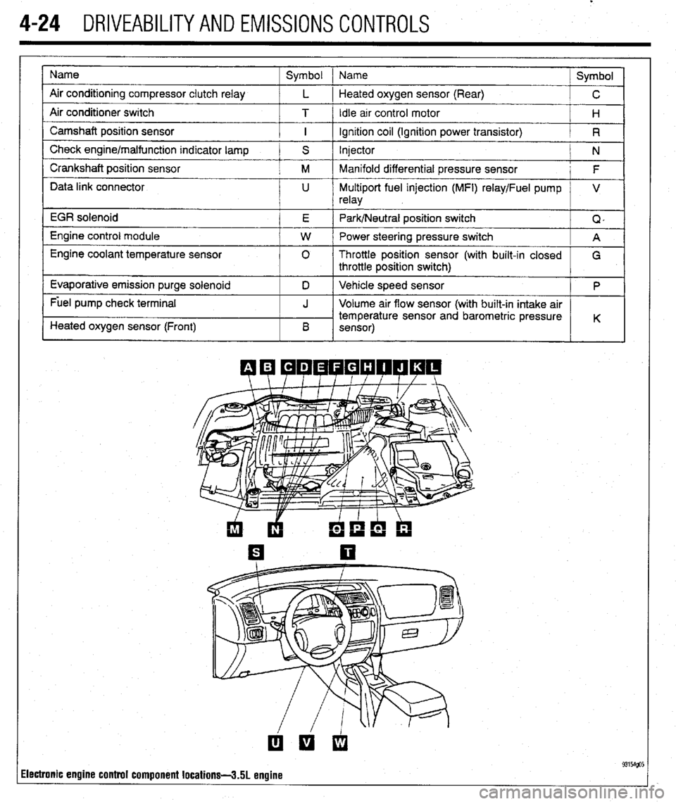
4-24 DRIVEABILITYAND EMISSIONS CONTROLS
Name
Air conditioning compressor clutch relay
Air conditioner switch
Camshaft position sensor
Check engine/malfunction indicator lamp
Crankshaft position sensor
Data link connector
EGR solenoid
Engine control module
Engine coolant temperature sensor
Evaporative emission purge solenoid
Fuel pump check terminal
Heated oxygen sensor (Front) Symbol 1 Name
Symbol
L 1 Heated oxygen sensor (Rear)
C
T / Idle arr control motor
H
I ignition coil (Ignition power transistor)
R
S Injector
N
M Manifold differential pressure sensor
F
U Multiport fuel injection (MFI) relay/Fuel pump V
relay
E Park/Neutral position switch
Q,
W Power steering pressure switch
A
0 Throttle position sensor (with built-in closed
G
throttle position switch)
D Vehicle speed sensor
P
J Volume air flow sensor (with built-in intake air
temperature sensor and barometric pressure
B K
sensor)
ilectronic engine control component locations-3.51 engine
Page 168 of 408
DRIVEABILITYAND EMISSIONS CONTROLS 4-25
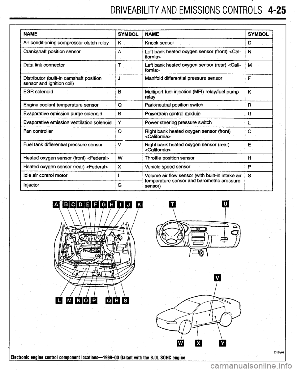
NAME
SYMBOL NAME SYMBOL
Air conditioning compressor clutch relay K
Knock sensor D
I Crankshaft position sensor
A Left bank heated oxygen sensor (front)
I I
Data link connector T Left bank heated oxygen sensor (rear)
I Distributor (built-in camshaft position
I J Manifold differential pressure sensor
I F
sensor and ignition coil)
I
EGR solenoid . B Multiport fuel injection (MFI) relay/fuel pump K
relay
1 Engine coolant temperature sensor
IQ 1 Park/neutral position switch IR
Euaporatiue.emission purge solenoid B
Powertraincontrol module LJ
l Evaporatiw5+eiiission ventilation solenoid Y
I Powersteering pressure switch
L
Fan controller 0 Right bank heated oxygen sensor (front) C
Fuel tank differential pressure sensor V Right bank heated oxygen sensor (rear) E
Heated oxygen sensor (front)
I
1 Heated oxygen sensor (rear)
Ip I
Idle air control motor
Injector I
G Volume air flow sensor (with built-in intake air S
temperature sensor and barometric pressure
sensor)
I I
93154@3 lectronic engine control component locations-199940 Galant with the 3.OL SOHC engine
Page 174 of 408
DRIVEABILITYAND EMISSIONSCONTROL-S 4-31
PO466 Purge Flow Sensor Circuit High Input
PO469 Purqe Flow Sensor Circuit Intermittent
PO470 Exhaust Pressure Sensor Malfunction
PO471 Exhaust Pressure Sensor Range/Perfor-
mance
PO472 Exhaust Pressure Sensor Low
PO473 Exhaust Pressure Sensor Hiah
PO474 Exhaust Pressure Sensor lnirmittent
PO475 Exhaust Pressure Control Valve Malfunc-
tion
PO476 Exhaust Pressure Control Valve
Range/Performance
PO477 Exhaust Pressure Control Valve Low
PO476 Exhaust Pressure Control Valve High
PO479 Exhaust Pressure Control Valve Intermit-
tent
PO460 Cooling Fan no 1 Control Circuit Mal-
function
PO461 Cooling Fan no. 2 Control Circuit Mal-
function
PO462 Cooling Fan no. 3 Control Circuit Mal-
function
PO463 Cooling Fan Rationality Check Malfunc-
tion
PO464 Cooling Fan Circuit Over Current
PO465 Cooling Fan Power/Ground Circuit Mal-
function
PO500 Vehicle Speed Sensor Malfunction
PO501 Vehicle Speed Sensor Range/Performance
PO502 Vehicle Speed Sensor Circuit Low Input
PO503 Vehicle Speed Sensor Intermittent/Er-
ratic/High
PO505 Idle Control System Malfunction
PO506 Idle Control System RPM Lower Than Ex-
pected
PO507 Idle Control System RPM Higher Than Ex-
pected
PO510 Closed Throttle Position Switch Malfunc-
tion
PO520 Engine Oil Pressure Sensor/Switch Circuit
Malfunction
PO521 Engine Oil Pressure Sensor/Switch
Range/Performance
PO522 Engine Oil Pressure Sensor/Switch Low
Voltage
PO523 Engine Oil Pressure Sensor/Switch High
Voltage
PO530 A/C Refrigerant Pressure Sensor Circuit
Malfunction
PO531 A/C Refrigerant Pressure Sensor Circuit
Range/Performance
PO532 A/C Refrigerant Pressure Sensor Circuit
Low Input
PO533 A/C Refrigerant Pressure Sensor Circuit
High Input
PO534 A/C Refrigerant Charge Loss
PO550 Power Steering Pressure Sensor Circuit
Malfunction
PO551 Power Steering Pressure Sensor Circuit
Range/Performance
PO552 Power Steering Pressure Sensor Circuit
Low Input
PO553 Power Steering Pressure Sensor Circuit
High Input
PO554 Power Steering Pressure Sensor Circiit
Intermittent
PO560 System Voltage Malfunction
PO561 System Voltage Unstable
PO562 System Voltage Low
PO563 Svstem Voltaoe Hlah
PO565 Ciuise Control On%ignal Malfunction
PO566 Cruise Control Off Signal Malfunction PO567 Cruise Control Resume Signal Malfunc-
tion
PO566 Cruise Control Set Signal Malfunction
PO569 Cruise Control Coast Signal Malfunction
PO570 Cruise Control Accel Signal Malfunction
PO571 Cruise Control/Brake Switch “A” Circuit
Malfunction
PO572 Cruise Control/Brake Switch “A” Circuit
Low
PO573 Cruise Control/Brake Switch “A” Circuit
High
P0574Through PO560 Reserved for Cruise
Codes
PO600 Serial Communication Link Malfunction
PO601 Internal Control Module Memory Check
Sum Error
PO602 Control Module Programming Error
PO603 Internal Control Module Keep Alive Mem-
ory (KAM) Error
PO604 Internal Control Module Random Access
Memory (RAM) Error
PO605 Internal Control Module Read Only Mem-
ory (ROM) Error
PO606 PCM Processor Fault
PO606 Control Module VSS Output “A” Malfunc-
tion
PO609 Control Module VSS Output “6” Malfunc-
tion
PO620 Generator Control Circuit Malfunction
PO621 Generator Lamp “L” Control Circuit Mal-
function
PO622 Generator Field “F” Control Circuit Mal-
function
PO650 Malfunction Indicator Lamp (MIL) Control
Circuit Malfunctron
PO654 Engine RPM Output Circuit Malfunction
PO655 Engine Hot Lamp Output Control Circuit
Malfunction
PO656 Fuel Level Output Circuit Malfunction
PO700 Transmission Control System Malfunction
PO701 Transmission Control System Range/Per-
formance
PO702 Transmission Control System Electrical
PO703 Torque Converter/Brake Switch “B” Circuit
Malfunction
PO704 Clutch Switch Input Circuit Malfunction
PO705 Transmission Range Sensor Circuit Mal-
function (PRNDL Input)
PO706 Transmission Range Sensor Circuit
Range/Performance
PO707 Transmission Range Sensor Circuit Low
Input
PO706 Transmission Range Sensor Circuit High
Input
PO709 Transmission Range Sensor Circuit Inter-
mittent
PO710 Transmission FluId Temperature Sensor
Circuit Malfunction
PO711 Transmission Fluid Temperature Sensor
Circuit Range/Performance
PO712 Transmission Fluid Temperature Sensor
Circuit Low Input
PO713 Transmission Fluid Temperature Sensor
Circuit High Input
PO714 Transmission Fluid Temperature Sensor
Circuit Intermittent
PO715 Input/Turbine Speed Sensor Circuit Mal-
function
PO716 Input/Turbine Speed Sensor Circuit
Range/Performance
PO717 InpWurbine Speed Sensor Circuit No
Signal PO716 Inputflurbine Speed Sensor Circuit Inter-
mittent
PO719 Torque Converter/Brake Switch “B” Circuit
Low
PO720 Output Speed Sensor Circuit Malfunction
PO721 Output Speed Sensor Circuit Range/Per-
formance
PO722 Output Speed Sensor Circuit No Signal
PO723 Output Speed Sensor Circuit Intermittent
PO724 Toraue Converter/Brake Switch “B” Circuit
High
PO725 Engine Speed Input Circuit Malfunction
PO726 Engine Speed Input Circuit Range/Perfor-
PO727 Engine Speed Input Circuit No Signal
PO726 Engine Speed Input Circuit Intermittent
PO730 Incorrect Gear Ratio
PO731 Gear no. 1 Incorrect Ratio
PO732 Gear no. 2 Incorrect Ratio
PO733 Gear no. 3 Incorrect Ratio
PO734 Gear no 4 Incorrect Ratio
PO735 Gear no. 5 Incorrect Ratio
PO736 Reverse Incorrect Ratio
PO740 Torque Converter Clutch Circuit Malfunc-
tion
PO741 Torque Converter Clutch Circuit Perfor-
mance or Stuck Off
PO742 Torque Converter Clutch Circuit Stuck On
PO743 Torque Converter Clutch Circuit Electrical
PO744 Torque Converter Clutch Circuit Intermit-
tent
PO745 Pressure Control Solenoid Malfunction
PO746 Pressure Control Solenoid Performance or
Stuck Off
PO747 Pressure Control Solenoid Stuck On
PO746 Pressure Control Solenoid Electrical
PO749 Pressure Control Solenoid Intermittent
PO750 Shift Solenoid “A” Malfunction
PO751 Shift Solenoid “A” Performance or Stuck
Off
PO752 Shift Solenoid “A” Stuck On
PO753 Shift Solenoid “A” Electrical
PO754 Shift Solenoid “A” Intermittent
PO755 Shift Solenoid “8 Malfunction
PO756 Shift Solenoid “B” Performance or Stuck
Oft
PO757 Shift Solenoid “B” Stuck On
PO756 Shift Solenoid “6” Electrical
PO759 Shift Solenoid “8” Intermittent
PO760 Shift Solenoid “C” Malfunction
PO761 Shift Solenoid “C” Performance Or Stuck
Oft
PO762 Shift Solenoid “C” Stuck On
PO763 Shift Solenoid “C” Electrical
PO764 Shift Solenoid “C” Intermittent
PO765 Shift Solenoid “D” Malfunction
PO766 Shift Solenoid “D” Performance Or Stuck
Oft
PO767 Shift Solenoid “D” Stuck On
PO766 Shift Solenoid “D” Electrical
PO769 Shift Solenoid “D” Intermittent
PO770 Shift Solenoid “E” Malfunction
PO771 Shift Solenoid “E” Performance Or Stuck
Off
PO772 Shift Solenoid “E” Stuck On
PO773 Shift Solenoid “E” Electrical
PO774 Shift Solenoid “E” Intermittent
PO760 Shift Malfunction
PO761 l-2 Shift Malfunction
PO762 2-3 Shift Malfunction
PO763 3-4 Shift Malfunction
PO764 4-5 Shift Malfunction
Page 177 of 408
.
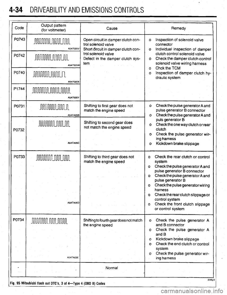
4-34 DRIVEABILITYAND EMISSIONS CONTROLS
Open circuit in damper clutch con-
trol solenoid valve
Short circuit in damper clutch con-
trol solenoid valve
Defect in the damper clutch sys- o Inspection of solenoid valve
connector
o Individual inspection of damper
clutch control solenoid valve
o Check the damper clutch control
solenoid valve wiring harness
o Chck the TCM
o Inspection of damper clutch hy-
draulic system
PO732 Shifting to first gear does not heckthe pulse generator A and
match the engine speed pulse generator B connector
o Check the pulse generator A and
Shifting to second gear does puls generator B
not match the engine speed o Checkthe one way clutch or rear
clutch
o Check the pulse generator wir-
ing harness
ASATAOSC o Kickdown brake slippage
PO733 Shifting to third gear does not o Check the rear clutch or control
match the engine speed system
o Check the pulse generator A and
pulse generator B connector
o Check the pulse generator A and
pulse generator B
o Checkthe pulse generatorwiring
harness
o Check the rear clutch slippage or
control system
A5ATA05D o Check the front clutch slippage
or control system
PO734
Shifting to fourth geardoes not match o Check the pulse generator A
the engine speed and B connector
o Check the pulse generator A
and B
o Kickdown brake slippage
o Check the end clutch or control
system
o Check the pulse generator wir-
ASATA05E ing harness
Normal
J
89446 :ig. 95 Mitsubishi flash out DTC’s, 3 of 4-Type 4 (OBD II) Codes
Page 216 of 408
CHASSIS ELECTRICiL 6-13
.
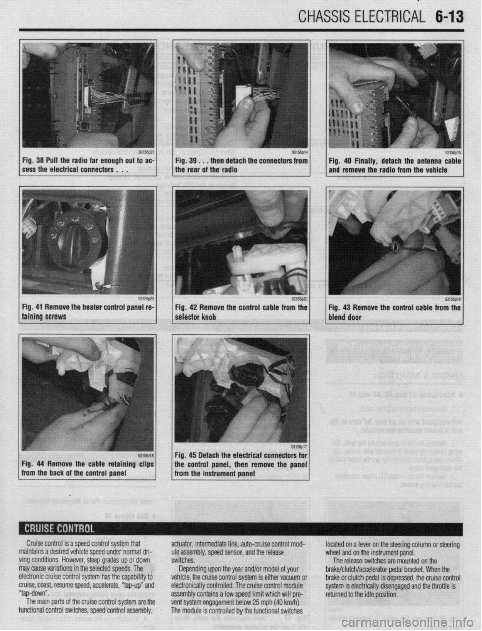
Fig. 38 Pull the radia far enough out to ac-
cess the electrical connectors . . . 9315fip14 Fig. 39. . . then detach the connectors from
I I Fig. 40 Finally, detach the antenna cable
the rear of the radio and remove the radio from the vehicle
Fig. 41 Remove the heater control panel re-
Fig. 42 Remove the control cable from the
g3156p1g / Fig 43 Remove the control cable from the
bleid door
Cruise control is a speed control system that
maintains a desired vehicle speed under normal dri-
ving conditions. However, steep grades up or down
may cause variations in the selected speeds. The !
electronic cruise control system has the capability to
cruise, coast, resume speed, accelerate, “tap-up” and
“tap-down”.
The main parts of the cruise control system are the
functional control switches, speed control assembly, actuator, intermediate link, auto-cruise control mod-
ule assembly, speed sensor, and the release
switches.
Depending upon the year and/or model of your
vehicle, the cruise control system is either vacuum or
electronically controlled. The cruise control module
assembly contains a low speed limit which will pre-
vent system engagement below 25 mph (40 km/h).
The module is controlled by the functional switches located on a lever on the steering column or steering
wheel and on the instrument panel.
The release switches are mounted on the
brake/clutch/accelerator pedal bracket. When the
brake or clutch pedal is depressed, the cruise control
system is electrically disengaged and the throttle is
returned to the idle position.
Page 217 of 408
6-14 CHASSIS ELECTRICAL
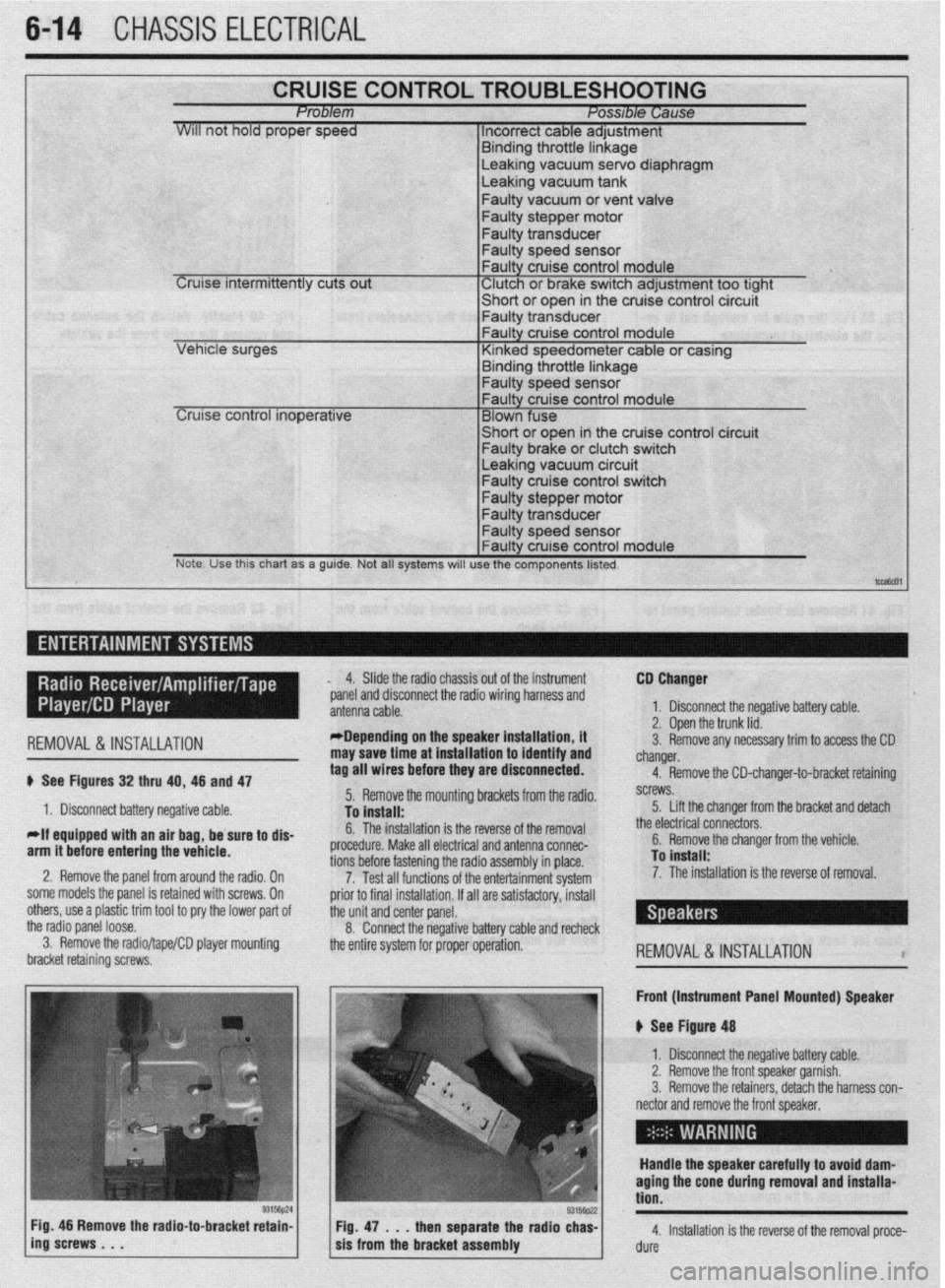
CRUISE CONTROL TROUBLESHOOTING Problem Posable Cause
WIII not hold proper speed 1 Incorrect cable adjustment
F.~. _I.~_ - 1L .-AL‘- I. I -
Cruise intermittently cuts out
trrnarng Inrome nnKage Leaking vacuum servo diaphragm
Leaking vacuum tank
Faulty vacuum or vent valve
Faulty stepper motor
Faulty transducer
Faulty speed sensor
Faulty cruise control module
‘ Clutch or brake switch adjustment too tight -chnrt *r nna* in the cruise control circuit
cer VI I”, . vt “y”‘,
I- Faulty transdu
Leaking vacuum circuit Faulty cruise control switch
Faulty stepper motor
Note. Use this chart as a guide. Not all systems will use the components listed.
t-,
I ,-- ,
REMOVAL&INSTALLATION
# See Figures 32 thru 40, 46 and 47
1. Disconnect battery negative cable.
*If equipped with an air bag, be sure to dis-
arm it before entering the vehicle.
2. Remove the panel from around the radio, On
some models the panel is retained with screws, On
others, use a plastic trim tool to pry the lower pad of
the radio panel loose.
3. Remove the radio/tape/CD player mounting
bracket retaining screws, 4. Slide the radio chassis out of the instrument
*panel and disconnect the radio wiring harness and
*Depending on the speaker installation, it
may save time at installation to identify and
tag all wires before they are disconnected.
5. Remove the mounting brackets from the radio.
To install:
6. The installation is the reverse of the removal
procedure. Make all electrical and antenna connec-
tions before fastening the radio assembly in place.
7. Test all functions of the entertainment system
prior to final installation. If all are satisfactory, install
the unit and center panel.
8. Connect the negative battery cable and recheck
the entire system for proper operation. CD Changer
1. Disconnect the negative battery cable.
2. Open the trunk lid.
3. Remove any necessary trim to access the CD
changer.
4. Remove the CD-changer-to-bracket retaining
screws.
5. Lift the changer from the bracket and detach
the electrical connectors.
6. Remove the changer from the vehicle.
To install:
7. The installation is the reverse of removal.
REMOVAL&INSTALLATION l
Front (Instrument Panel Mounted) Speaker
u See Figure 48
1. Disconnect the negative battery cable.
2. Remove the front speaker garnish.
3. Remove the retainers, detach the harness con-
nector and remove the front speaker,
Handle the speaker carefully to avoid dam-
aging the cone during removal and installa-
tion.
4. Installation is the reverse of the removal proce-
dure
Page 280 of 408
MANUAL TRANSAXLE 7-2
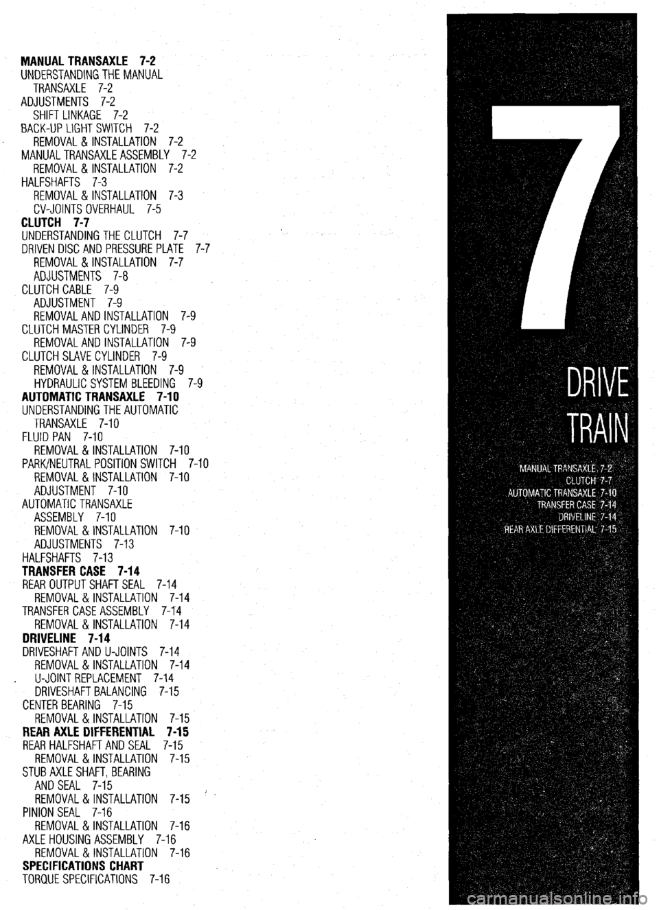
UNDERSTANDINGTHEMANUAL
TRANSAXLE 7-2
ADJUSTMENTS 7-2
SHIFT LINKAGE 7-2
BACK-UP LIGHT SWITCH 7-2
REMOVAL & INSTALLATION 7-2
MANUALTRANSAXLEASSEMBLY 7-2
REMOVAL &INSTALLATION 7-2
HALFSHAFTS 7-3
REMOVAL & INSTALLATION 7-3
CV-JOINTS OVERHAUL 7-5
CLUTCH 7-7
UNDERSTANDINGTHE CLUTCH 7-7
DRIVEN DISC AND PRESSURE PLATE 7-i'
REMOVAL &INSTALLATION 7-7
ADJUSTMENTS 7-8
CLUTCH CABLE 7-9
ADJUSTMENT 7-9
REMOVAL AND INSTALLATION 7-9
CLUTCH MASTERCYLINDER 7-9
REMOVALANDINSTALLATION 7-9
CLUTCH SLAVE CYLINDER 7-9
REMOVAL &INSTALLATION 7-9
HYDRAULIC SYSTEM BLEEDING 7-9
AUTOMATIC TRANSAXLE 7-10
UNDERSTANDINGTHEAUTOMATIC
TRANSAXLE 7-10
FLUID PAN 7-10
REMOVAL & INSTALLATION 7-10
PARK/NEUTRAL POSITION SWITCH 7-10
REMOVAL & INSTALLATION 7-10
ADJUSTMENT 7-10
AUTOMATIC TRANSAXLE
ASSEMBLY 7-10
REMOVAL &INSTALLATION 7-10
ADJUSTMENTS 7-13
HALFSHAFTS 7-13
TRANSFER CASE 7-14
REAR OUTPUTSHAFTSEAL 7-14
REMOVAL & INSTALLATION 7-14
TRANSFER CASE ASSEMBLY 7-14
REMOVAL &INSTALLATION 7-14
DRIVELINE 7-14
DRIVESHAFT AND U-JOINTS 7-14
REMOVAL & INSTALLATION 7-14
. U-JOINT REPLACEMENT 7-14
DRIVESHAFT BALANCING 7-15
CENTER BEARING 7-15
REMOVAL & INSTALLATION 7-15
REAR AXLE DIFFERENTIAL 7-15
REAR HALFSHAFTAND SEAL 7-15
REMOVAL &INSTALLATION 7-15
STUBAXLESHAFT,BEARlNG
AND SEAL 7-15
REMOVAL&INSTALLATION 7-15 '
PINION SEAL 7-16
REMOVAL&INSTALLATION 7-16
AXLEHOUSING ASSEMBLY 7-16
REMOVAL&INSTALLATION 7-16
SPECIFICATIONS CHART
TORQUE SPECIFICATIONS 7-16