1900 MITSUBISHI DIAMANTE center console
[x] Cancel search: center consolePage 151 of 408
.
4-8 DRIVEABILITYAND EMISSIONS CONTROLS
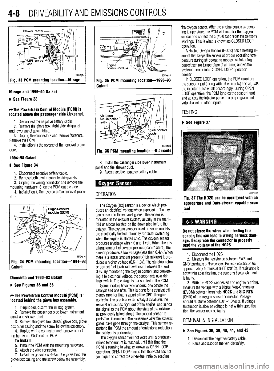
93154g17 Fig. 33 PCM mounting location-Mirage
Mirage and 1999-00 Galant
) See Figure 33
*The Powertrain Control Module (PCM) is
located above the passenger side kickpanel.
1. Disconnect the negative battery cable.
2. Remove the @love box, right side kickpanel
and lower panel assemblies.
3. Unplug the connectors and remove fasteners.
Remove the PCM.
4. Installation is the reverse of the removal proce-
dure.
1994-98 Galant
+ See Figure 34
1, Disconnect negative battery cable.
2. Remove both center console side panels.
3. Unplug the wiring connector and remove the
mounting hardware. Slide the PCM out the side.
4. installation is the reverse of the removal proce-
dure.
Diamante and 1990-93 Galant
) See Figures 35 and 38
*The Powertrain Control Module (PCM) is
located behind the glove box assembly.
1, If equipped, disarm the air bag system
2. Remove the passenger side lower instrument
panel and shower duct.
3. Remove the glove box striker, glove box, glove
box outer casing and the screw below the assembly.
4. Unplug wiring connector and remove mount-
ing hardware. Slide out the PCM.
To install: 5. Install the PCM with the mounting hardware.
6. Attach the wire connector.
7. Install the glove box striker, the glove box, the
glove box casing and the screw below the assembly.
Q3154g15 Fig. 35 PCM mounting location-1990-93
Galant
93154g16 Fig. 38 PCM mounting location-Diamante
8. Install the passenger side lower instrument
panel and the shower duct.
9. Reconnect the negative battery cable
OPERATION
The Oxygen (02) sensor is a device which pro-
duces an electrical voltage when exposed to the oxy-
gen present in the exhaust gases. The sensor is
mounted in the exhaust system, usually in the mani-
fold or a boss located on the down pipe before the
catalyst. The oxygen sensors used on some models
are electrically heated internally for faster switching
when the engine is started cold. The oxygen sensor
produces a voltage within 0 and 1 volt. When there is
a large amount of oxygen present (lean mixture), the
sensor produces a low voltage (less than 0.4~). When
there is a lesser amount present (rich mixture) it pro-
duces a higher voltage (0.6-I .Ov). The stoichiometric
or correct fuel to air ratio will read between 0.4 and
0.6~. By monitoring the oxygen content and convert-
ing it to electrical voltage, the sensor acts as a rich-
lean switch. The voltage is transmitted to the PCM.
Some models have two sensors, one before the
catalyst and one after. This is done for a catalyst eff i-
ciency monitor that is a part of the OBD-II engine
controls. The one before the catalyst measures the
exhaust emissions right out of the engine, and sends
the signal to the PCM about the state of the mixture
as previously talked about. The second sensor re-
ports the difference in the emissions after the exhaust
gases have gone through the catalyst. This sensor re-
ports to the PCM the amount of emissions reduction
the catalyst is performing.
The oxygen sensor will not work until a predeter-
mined temperature is reached, until this time the
PCM is running in what as known as OPEN LOOP
operation. OPEN LOOP means that the PCM has not
yet begun to correct the air-to-fuel ratio by reading the oxygen sensor. After the engine comes to operat-
ing temperature, the PCM will monitor the oxygen
sensor and correct the air/fuel ratio from the sensor’s
readings. This is what is known as CLOSED LOOP
operation.
A Heated Oxygen Sensor (H02S) has a heating el-
ement that keeps the sensor at proper operatmg tem-
perature during all operating modes. Maintaining
correct sensor temperature at all times allows the
system to enter into CLOSED LOOP operation
sooner.
In CLOSED LOOP operation, the PCM monitors
the sensor input (along with other inputs) and adjusts
the injector pulse width accordingly. During OPEN
LOOP operation, the PCM ignores the sensor input
and adjusts the injector pulse to a preprogrammed
value based on other inputs.
TESTING
# See Figure 37
93154p36 Fig. 37 The HD2S can be monitored with an
appropriate and Data-stream capable scan
tool
Do not pierce the wires when testing this
sensor; this can lead to wiring harness dam-
age. Backprobe the connector to properly
read the voltage of the HD2S.
1. Disconnect the H02S.
2. Measure the resistance between PWR and
GND terminals of the sensor. Resistance should be
approximately 6 ohms at 68°F (20°C) If resistance is
not within specification, the sensor’s heater element
is faulty.
3. With the H02S connected and engine running,
measure the voltage with a Digital Volt-Ohmmeter
(DVOM) between terminals
HD2S and SIG RTN (GND) of the oxygen sensor connector. Voltage
should fluctuate between 0.01-l .O volts. If voltage
fluctuation is slow or voltage is not within specifica-
tion, the sensor may be faulty.
REMOVAL &INSTALLATION
) See Figures 38, 39, 40, 41, and 42
1. Disconnect the negative battery cable
2. Raise and support the vehicle safely.
Page 213 of 408
640 CHASSIS ELECTRICAL
careful not to allow anything to come in contact with
the air bag unit.
16. Remove the glove box lamp assembly.
17. Remove the remaining instrument panel
mounting screws and remove the instrument panel
from the vehicle.
18. Remove the left side foot shower ductwork,
lap cooler duct and center duct.
19. Remove the front and center reinforcements
and center stay assembly.
20. Remove the air distribution duct assembly.
21. Detach all connectors from heater-box-
mounted items.
22. Remove the heater box mounting screws and
nut, then remove the unit from the vehicle.
23. Disassemble on a workbench. Remove the
heater core from the heater case.
To install:
24. Thoroughly clean and dry the inside of the
case and install the heater core and all related parts.
25. Install the heater unit to the vehicle and install
the mounting screws and nut. Be sure the evaporator
case and heater case are fitted together properly. At-
tach all connectors to heater-box-mounted items.
26. Install the air distribution duct assembly. In-
stall the front and center reinforcements and center
stay assembly.
27. Install the center duct, lap cooler duct and left
side foot shower duct.
28. Install the instrument panel and mounting
screws.
29. Install the glove box lamp assembly.
30. Secure the steering column and attach all
steering column connectors.
31. Install the speedometer cable adapter to the
instrument panel.
32. Install the instrument cluster and the instru-
ment cluster bezel.
33. Install the speakers to the top of the instru-
ment panel.
34. Install the cup holder.
35. Install the climate control system control
head.
36. Install the stereo entertainment system and
bezel.
37. Install the screw below the glove box assem-
bly, and the entire glove box unit.
38. Install the steering column covers.
39. Install the knee protector support bracket, the
protector and the decorative plugs.
40. Install the console and the ashtray. 41. Install the right side foot shower duct.
42. Install the passenger side undercover.
43. Connect the heater hoses to the core tubes.
44. Fill the cooling system.
45. Connect the negative battery cable and check
the entire climate control system for proper operation
and leaks.
Galant
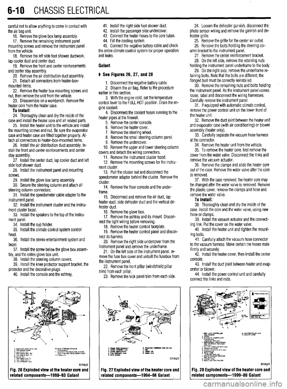
# See Figures 26, 27, and 28
1. Disconnect the negative battery cable.
2. Disarm the air bag. Refer to the procedure
earlier in this section.
3. With the engine cold, set the temperature
control lever to the FULL HOT position. Drain the en-
gine coolant.
4. Disconnect the coolant hoses running to the
heater pipes at the firewall.
5. Remove the center console.
6. Remove the heater cover.
7. Remove the steering wheel.
8. Remove the small steering column panel.
9. Remove the undercover.
10. Remove the upper and lower steering column
covers and detach the wiring connectors.
11. Remove the instrument cluster hood.
12. Remove the mounting screws for the instru-
ment cluster.
13. Pull the cluster out and disconnect the
speedometer adapter behind the cluster. Remove the
cluster.
14. Remove the floor console and the under-
frame.
15. Disconnect and remove the air duct, lap
heater duct, side defroster duct and the vertical de-
froster duct.
16. Remove the glove box.
17. Remove the ashtray and its mount. Discon-
nect the light wiring before removing.
18. Remove the heater control faceplate.
19. Remove the heater control panel and discon-
nect its harness.
20. Remove the right side undercover from the
instrument panel and remove the underframe.
21. On the left side of the instrument panel, re-
move the fuse box cover and unbolt the fusebox from
the instrument panel.
22. Remove the front pillar (windshield pillar
trim) from each pillar.
23. Remove the kick panel trim from each side.
Fig. 26 Exploded view of the heater core and
related components-1990-93 Galant
:IQ. 27 Exploded view of the heater core and
-elated components-1994-98 Galant 24. Loosen the defroster garnish, disconnect the
photo sensor wiring and remove the garnish and de-
froster grille.
25. Remove the grille for the center air outlet.
26. Remove the bolts holding the steering col-
umn bracket to the instrument panel.
27, Remove the center reinforcement bracket.
28. On the left side, remove the retaining nuts
holding the instrument panel underframe to the body.
29. On the right side, remove the underframe re-
taining bolts. Note that the bolts are different; the
flanged bolt must be correctly reinstalled.
30. Remove the remaining nuts and bolts holding
the instrument panel. As the instrument panel comes
loose, label and disconnect the wiring harnesses.
Carefully remove the instrument panel.
31. If equipped with automatic climate control,
remove the power control unit on the lower front of
the heater unit.
32. Remove the duct joint between the heater unit
and evaporator case (with air conditioning) or blower
assembly (heater only).
33. Carefully separate the vacuum hose harness
at the connector.
34. Remove the heater unit from the vehicle.
35. To remove the heater core, first remove the
cover from the water valve. Disconnect the links and
remove the vacuum actuator.
36. Remove the clamps and slide the heater core
out of the case. Remove the water valve after the core
is removed.
37. With the case removed, the heater core may
be changed after the water valve is removed. Remove
the plastic cover, remove the clamps and hose and
remove the water valve.
To install:
38. Thoroughly clean and dry the inside of the
case. Install the core and the water valve, using new
hose or clamps.
39. Install the vacuum actuator and the connect-
ing link. Put the cover on the water valve.
40. Install the heater unit and tighten the mount-
ing bolts.
41. Carefully attach the vacuum hose connector
to the vacuum harness. Make certain the hoses mate
firmly and securely.
42. Install the heater cover, then install the center
console.
43. Install the duct joint between heater and evap-
orator or blower.
44. Install the power control unit and carefully
connect the links and rods.
Fig. 28 Exploded view of the heater core and
related components-1999-00 Galant
Page 214 of 408
CHASSIS ELECTRICAL 6-11
45. Install the heater hoses under the hood.
46. Install the mstrument panel by reversing its
removal procedure.
47. Install the center console.
48. install the upper and lower steering column
covers.
49. Install the center panel undercover.
50. Install the small column panel.
51. Install the steering wheel.
52. Fill the cooling system.
53. Connect the negative battery cable and check
the entire climate control system for proper operation
and leaks.
Mirage
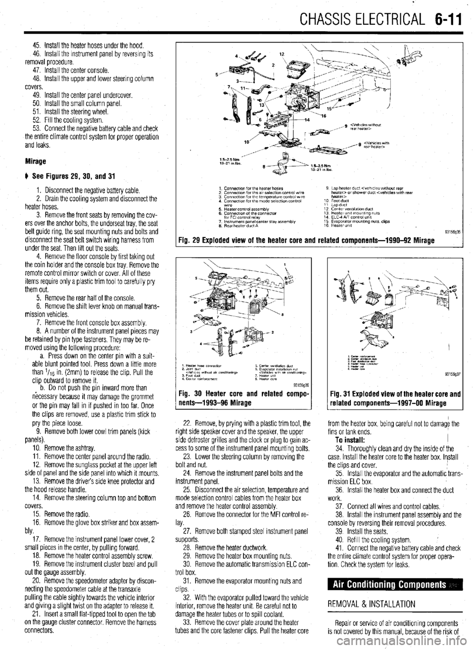
# See Figures 29, 30, and 31
1. Disconnect the negative battery cable.
2. Drain the cooling system and disconnect the
heater hoses.
3. Remove the front seats by removing the cov-
ers over the anchor bolts, the underseat tray, the seat
belt guide ring, the seat mounting nuts and bolts and
disconnect the seat belt switch wiring harness from
under the seat. Then lift out the seats
4. Remove the floor console by first taking out
the coin holder and the console box tray. Remove the
remote control mirror switch or cover. All of these
items require only a plastic trim tool to carefully pry
them out.
5. Remove the rear half of the console.
6. Remove the shift lever knob on manual trans-
mission vehicles.
7. Remove the front console box assembly.
8. A number of the instrument panel pieces may
be retamed by pin type fasteners. They may be re-
moved using the following procedure:
a. Press down on the center pin with a suit-
able blunt pointed tool. Press down a little more
than l/re in. (2mm) to release the clip. Pull the
clip outward to remove it.
b. Do not oush the oin inward more than
necessary because it may damage the grommet
or the pin may fall in if pushed in too far. Once
the clips are removed, use a plastic trim stick to
pry the piece loose.
9. Remove both lower cowl trim panels (kick
panels).
10. Remove the ashtray.
11. Remove the center panel around the radio.
12. Remove the sunglass pocket at the upper left
side of panel and the side panel into which it mounts,
13. Remove the drivers side knee protector and
the hood release handle.
14. Remove the steering column top and bottom
covers.
15. Remove the radio.
16. Remove the glove box striker and box assem-
bly.
17. Remove the instrument panel lower cover, 2
small pieces in the center, by pulling forward.
18. Remove the heater control assembly screw.
19. Remove the instrument cluster bezel and pull
out the Qauge assembly.
20. Remove the speedometer adapter by discon-
necting the speedometer cable at the transaxle
pulling the cable Sightly towards the vehicle interior
and giving a Slight twist on the adapter to release it.
21. Insert a small flat-tipped tool to open the tab
on the QauQe cluster connector. Remove the harness
connectors.
Fig. 29 Exploded view of the heater core and related components-1990-92 Mirage
93l%Q% Fig. 30 Heater core and related compo-
nents-1993-96 Mirage
22. Remove, by prying with a plastic trim tool, the
right side speaker cover and the speaker, the upper
side defroster grilles and the clock or plug to gain ac-
cess to some of the instrument panel mounting bolts.
23. Lower the steering column by removing the
bolt and nut.
24. Remove the instrument panel bolts and the
instrument panel.
25 Drsconnect the air selection, temperature and
mode selection control cables from the heater box
and remove the heater control assembly.
26. Remove the connector for the MFI control re-
lay.
27. Remove both stamped steel instrument panel
supports.
28. Remove the heater ductwork.
29. Remove the heater box mounting nuts.
30 Remove the automatic transmission ELC con-
trol box.
31. Remove the evaporator mounting nuts and
clips.
32. With the evaporator pulled toward the vehicle
interior, remove the heater unit. Be careful not to
damage the heater tubes or to spill coolant.
33. Remove the cover plate around the heater
tubes and the core fastener clips. Pull the heater core 34. Thoroughly clean and dry the inside of the
case. Install the heater core to the heater box. Install
the clips and cover,
35. Install the evaporator and the automatic trans-
mission ELC box.
36. Install the heater box and connect the duct
Fig. 31 Exploded view of the heater core and
related components-1997-00 Mirage
from the heater box, being careful not to damage the
fins or tank ends.
To install: I
work.
37. Connect all wires and control cables,
38. Install the instrument panel assembly and the
console by reversmg their removal procedures.
39 Install the seats.
40. Refill the cooling system.
41. Connect the negative battery cable and check
the entire climate control system for proper opera-
tion Check the system for leaks.
REMOVAL &INSTALLATION
Repair or service of air Conditioning components
is not covered by this manual, because of the risk of
Page 356 of 408
‘I
9-20 ,BRAKES
1. Remove the wheel cylinder from the vehicle
and place on a clean workbench.
2. First remove and discard the old rubber
boots, then withdraw the pistons. Piston cylinders are
equipped with seals and a spring assembly, all lo-
cated behind the pistons in the cylinder bore.
3. Remove the remaining inner components,
seals and spring assembly. Compressed air may be
useful in removing these components. If no com-
pressed air is available, be VERY careful not to score
the wheel cylinder bore when removing parts from it. Discard all components for which replacements were
supplied in the rebuild kit.
4. Wash the cylinder and metal parts in dena-
tured alcohol or clean brake fluid.
Never use a mineral-based solvent such as
gasoline, kerosene or paint thinner for clean-
ing purposes. These solvents will swell rub-
ber components and quickly deteriorate
them. 5. Allow the parts to air dry or use compressed
air. Do not use rags for cleaning, since lint will re-
main in the cylinder bore.
6. Inspect the piston and replace it if it shows
scratches.
7. Lubricate the cylinder bore and seals using
- clean brake fluid.
8. Position the spring assembly.
9. Install the inner seals, then the pistons.
IO. Insert the new boots into the counterbores bv
hand. Do not lubricate the boots,
11, Install the wheel cylinder,
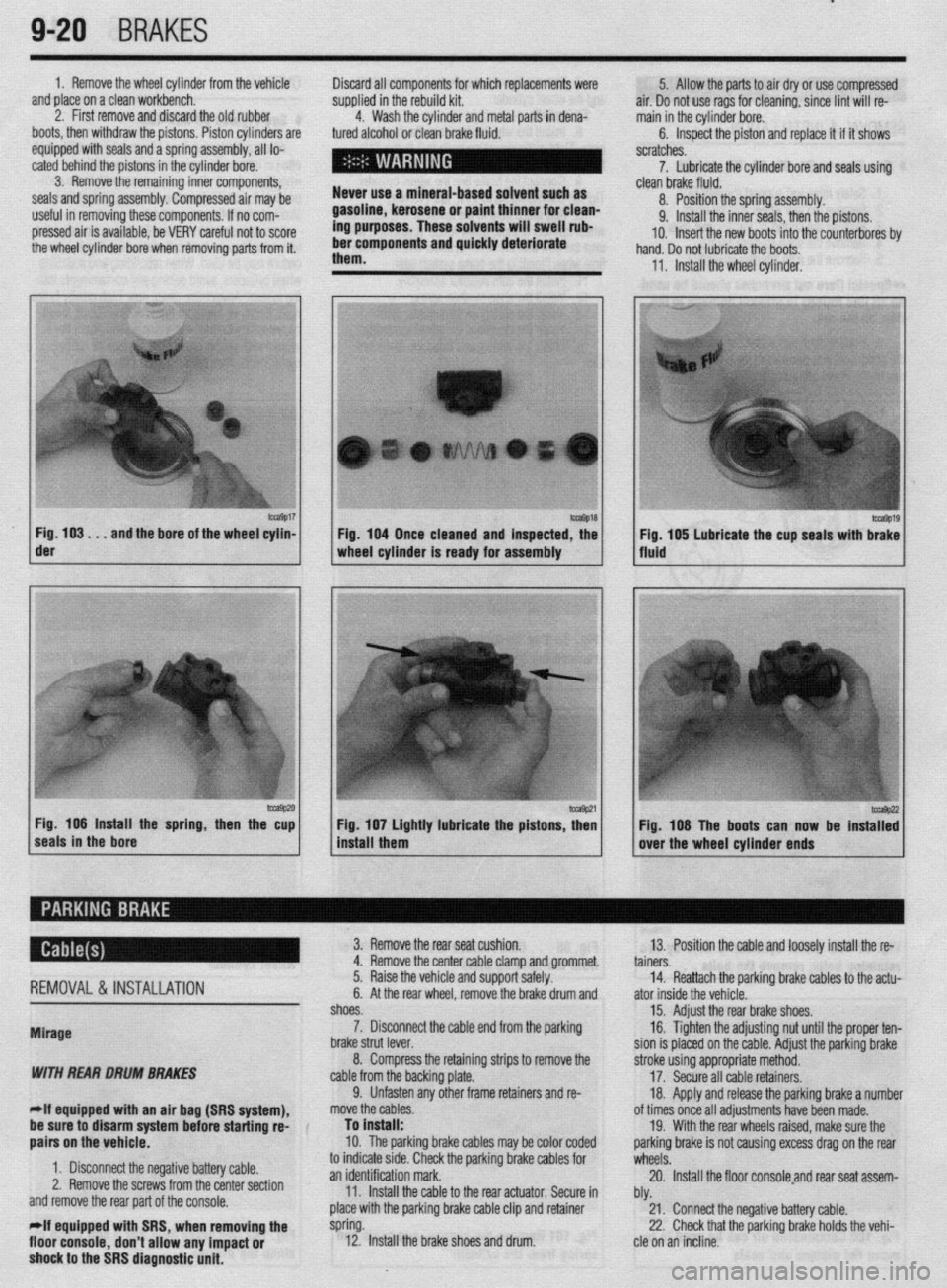
m9017 Fig. 103. . .
and the bore of the wheel cylin- der
-9P20 Fig. 106 Install the spring, then the cup
seals in the bore 1 Fig. 104 Once cleaned and inspected, the
1 wheel cylinder Is ready for assembly
1 install them Fig 107 Lightly lubricate the pistons z
’ Fig. 108 The boots can now be instaT:
over the wheel cylinder ends
REMOVAL& INSTALLATION
Mirage
WITH REAR DRUM BRAKES
-If equipped witti an air bag (SRS system), 3. Remove the rear seat cushion.
13. Position the cable and loosely install the re-
4. Remove the center cable clamp and grommet.
tainers.
5. Raise the vehicle and support safely.
14. Reattach the parking brake cables to the actu-
6. At the rear wheel, remove the brake drum and
ator inside the vehicle.
shoes.
15. Adjust the rear brake shoes.
7. Disconnect the cable end from the parking
16. Tighten the adjusting nut until the proper ten-
brake strut lever.
sion is placed on the cable. Adjust the parking brake
8. Compress the retaining strips to remove the
stroke using appropriate method.
cable from the backing plate.
17. Secure all cable retainers,
9. Unfasten any other frame retainers and re-
18. Apply and release the parking brake a number
move the cables.
of times once all adjustments have been made.
be sure to disarm system
befok starting rd-
aairs on the vehicle. To install:
10. The parkinq brake cables mav be color coded 19. With the rear wheels raised, make sure the
oarkino brake is not causina excess draa on the rear
1. Disconnect the negative battery cable.
2. Remove the screws from the center section
and remove the rear part of the console.
*If equipped with SRS, when removing the
floor console,
don’t allow any impact or
shock to the SRS diagnostic unit. to indicate stde. Check the parking brake cables for
wheels: .A
an identification mark.
20. Install the floor consoleand rear seat assem-
11. Install the cable to the rear actuator. Secure in
bly.
place with the parking brake cable clip and retainer
21. Connect the negative battery cable.
spring.
22. Check that the parking brake holds the vehi-
12. Install the brake shoes and drum.
cle on an incline.
Page 357 of 408
BRAKES 9-21
WITH REAR DISC BRAKES
*If equipped with an air bag (SRS system),
be sure to disarm the system before starting
repairs on the vehicle.
1. Disconnect the negative battery cable.
2. Remove the screws from the center section
and remove the rear part of the console.
*If equipped with SRS, when removing the
floor console, don’t allow any impact or
shock to the SRS diagnostic unit.
3. Remove the rear seat cushion.
4. Loosen the cable adjusting nut and discon-
nect the rear brake cables from the actuator.
5. Remove the center cable clamp and grommet.
6. Raise the vehicle and support safely.
7. Remove the parking brake cable clip and re-
tainer spring.
8. Disconnect the cable end from the parking
brake assembly.
9. Unfasten any remaining frame retainers and
remove the cables from the vehicle.
To install: IO. The parking brake cables may be color coded
to indicate side. Check the parking brake cables for
an identification mark.
11. Install the cable to the rear actuator. Secure in
place with the parking brake cable clip and retainer
spring.
12. Position the cable and loosely install the re-
tainers.
13. Reattach the parking brake cables to the actu-
ator inside the vehicle.
14. Tighten the adjusting nut until the proper ten-
sion is placed on the cable. Adjust the parking brake
. stroke using appropriate method.
15. Secure all cable retainers.
16. Apply and release the parking brake a number
of times once all adjustments have been made.
17. With the rear wheels raised, make sure the
parking brake is not causing excess drag on the rear
wheels.
18. Install the floor console and rear seat assem-
bly.
19. Connect the negative battery cable.
20. Check console electrical components for
proper operation.
21. Road test the vehicle and check for proper
brake operation.
22. Check that the parking brake holds the vehi-
cle on an incline.
1990-93 Galant
WITH REAR DRUM BRAKES
1. Disconnect the negative battery cable.
2. Remove the center console as follows:
a. Remove both side cover panels.
b. Remove the shifter knob on manual
transaxle models. Remove the spacer trim piece
on automatic transaxle models.
c. Remove the switch panel/box and remove
the two screws beneath the panel/box.
d. Remove the radio trim panel.
e. Remove the radio and tape player.
f. Remove the console inner panel and re-
move the two screws for beneath the panel.
g. Remove the remaining screws from the
sides of the console. h. Remove the console assembly from the ve-
hicle.
3. While pressing downward on the front of the
rear seat cushion, release the locking levers and re-
move the seat cushion.
4. Loosen the cable adjustment at the cable
equalizer.
5. Remove the center cable clamp and grommet.
6. Raise the vehicle and support safely.
7. At the rear wheel, remove the brake drum and
shoes.
8. Disconnect the cable end from the parking
brake strut lever.
9. Remove the snapring securing the cable to
the backing plate.
IO. Unfasten any other frame retainers and re-
move the cables.
To install:
*The parking brake cables may be color
coded to indicate side. Check the parking
brake cables for an identification mark.
11. Install the cable to the rear actuator. Secure in
place with the parking brake cable clip and snapring.
12. Install the brake shoes and drum.
13. Position the cable and loosely install the re-
tainers
14. Reattach the parking brake cables to the actu-
ator inside the vehicle. Tighten the adjusting nut until
the proper tension is placed on the cable. Adjust the
parking brake stroke using appropriate method.
15. Secure all cable retainers.
16. Apply and release the parking brake a number
of times once all adjustments have been made.
17. Adjust the rear brakes and parking brake ca-
bles.
18. Check the rear wheels to confirm that the rear
brakes are not dragging.
19. Install the center console and rear seat cush-
ion.
20. Connect the negative battery cable.
21. Check console electrical components for
proper operation.
22. Check that the parking brake holds the vehi-
cle on an incline.
WITH REAR DISC BRAKES
1. Disconnect the negative battery cable.
2. Remove the center console as follows:
a. Remove both side cover panels.
b. Remove the shifter knob on manual
transaxle models. Remove the spacer trim piece
on automatic transaxle models.
c. Remove the switch panel/box and remove
the two screws beneath the panel/box.
d. Remove the radio trim panel.
e. Remove the radio and tape player.
f. Remove the console inner panel and re-
move the two screws from beneath the panel.
g. Remove the remaining screws from the
sides of the console.
h. Remove the console assembly from the ve-
hicle.
3. While pressing downward on the front of the
rear seat cushion, release the locking levers and re-
move the seat cushion.
4. Loosen the cable adjusting nut and discon-
nect the rear brake cables from the actuator.
5. Remove the center cable clamp and grommet.
6. Raise the vehicle and support it safely. 7. At the rear caliper assembly, remove the
parking brake cable clip and retainer spring.
8. Disconnect the cable end from the caliper.
9. Unfasten any remaining frame retainers and
remove the cables from the vehicle.
To install:
*The parking brake cables may be color
coded to indicate side. Check the parking
brake cables for an identification mark.
IO. Connect the cable to the actuator at the brake
caliper. Secure in place with the parking brake cable
clip and retainer spring.
11. Position the cable and loosely install the re-
tainers.
12. Reattach the parking brake cables to the actu-
ator inside the vehicle. Tighten the adjusting nut until
the proper tension is placed on the cable.
13. Adjust the parking brake stroke using appro-
priate method.
14. Secure all cable retainers.
15. Apply and release the parking brake a number
of times once all adjustments have been made.
16. With the rear wheels raised, make sure the
parking brake is not causing excess drag on the rear
wheels.
17. Install the floor console assembly and rear
seat cushion.
18. Connect the negative battery cable.
19. Check console electrical components for
proper operation.
20. Road test the vehicle and check for proper
brake operation.
21. Check that the parking brake holds the vehi-
cle on an incline.
1994-00 Galant
WITH REAR DRUM BRAKES
1. Disconnect the negative battery cable.
The SRS control unit is mounted beneath the
center console. Use care when working with
the center console assembly not to impact or
shock the control unit.
2. Remove the center floor console assembly as
follows:
a. Remove the shifter knob on models
equipped with a manual transaxle.
b. Remove the shifter trim panel.
c. Remove the center instrument panel.
d. Remove the panel box from the console
assembly.
e. Remove the two screws from the center of
the console.
f. Remove the four side panel screws and re-
move the console from the vehicle.
3. Loosen the cable adjuster nut, then remove
the parking brake cable by pulling it from the passen-
ger compartment.
4. Raise the vehicle and support safely.
5. At the rear wheel, remove the brake drum and
shoes.
6. Disconnect the cable end from the parking
brake strut lever. Compress the retaining strips to re-
move the cable from the backing plate.
Page 358 of 408
--7 9-22
BRAKES
7. Unfasten any other frame retainers and re-
move the cables.
To install: 8. Install the cable to the rear actuator. Secure in ’
place with the parking brake cable clip and retainer
spring. b. Remove the shifter trim panel.
c. Remove the center instrument panel.
d. Remove the panel box from the console
assembly.
e. Remove the two screws from the center of
the console.
9. Install the brake shoes and drum.
10. Position the cable and loosely install the re-
tainers.
Il. Reattach the parking brake cables to the actu-
ator inside the vehicle.
12. Tighten the adjusting nut until the proper ten-
sion is placed on the cable.
13. Adjust the parking brake stroke using appro-
priate method.
14. Secure all cable retainers. Apply and release
the parking brake a number of times once all adjust-
ments have been made.
15. Assemble the interior components which
were removed.
16. Adjust the rear brakes and parking brake ca-
bles.
17. Connect the negative battery cable.
18. Check the rear wheels to confirm that the rear
brakes are not dragging.
19. Check that the parking brake holds the vehi-
cle on an incline.
WITH REAR DISC BRAKES
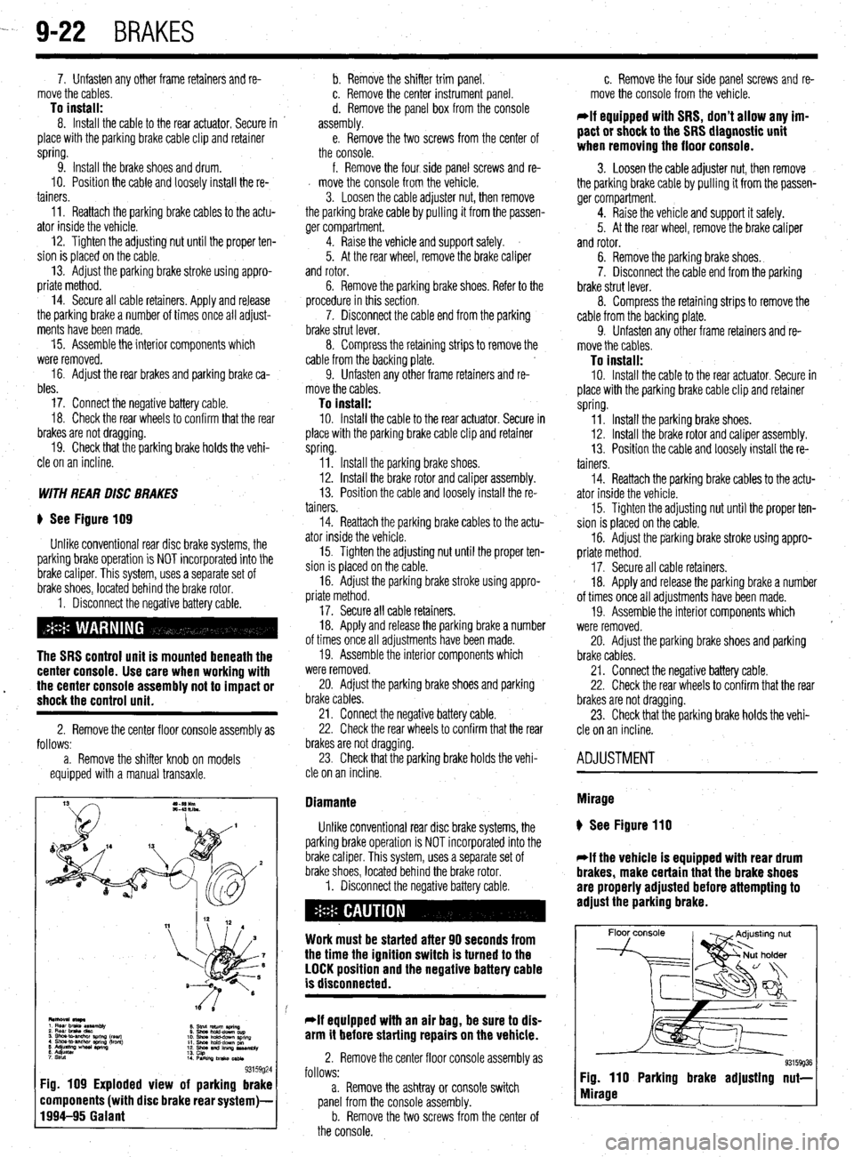
) See Figure 109
Unlike conventional rear disc brake systems, the
parking brake operation is NOT incorporated into the
brake caliper. This system, uses a separate set of
brake shoes, located behind the brake rotor.
1. Disconnect the negative battery cable.
The SRS control unit is mounted beneath the
center console. Use care when working with
17. Secure all cable retainers.
18. Apply and release the parking brake a number
of times once all adjustments have been made.
19. Assemble the interior components which
were removed.
l the center console assembly not to impact or 20. Adjust the parking brake shoes and parking shock the control unit. brake cables.
2. Remove the center floor console assembly as
follows:
a. Remove the shifter knob on models
equipped with a manual transaxle. 21. Connect the negative battery cable.
22. Check the rear wheels to confirm that the rear
brakes are not dragging.
23. Check that the parking brake holds the vehi-
cle on an incline.
8. Stnd return aring
0 Shwhdd-downcup
10. shna hchd-dPwn SpnnQ
11. Shm hold-dcwn pm
12. shoe and lllllnp us*mbly
13.
14 cap
PwkilvJbnko~
93159g24 Fig. 109 Exploded view of parking brake
components (with disc brake rear system)-
1994-95 Galant
f. Remove the four side panel screws and re-
d move the console from the vehicle.
3. Loosen the cable adjuster nut, then remove
the parking brake cable by pulling it from the passen-
ger compartment.
4. Raise the vehicle and support safely.
5. At the rear wheel, remove the brake caliper
and rotor.
6. Remove the parking brake shoes. Refer to the
procedure in this section.
7. Disconnect the cable end from the parking
brake strut lever.
8. Compress the retaining strips to remove the
cable from the backing plate.
9. Unfasten any other frame retainers and re-
move the cables.
To install: IO. Install the cable to the rear actuator. Secure in
place with the parking brake cable clip and retainer
spring.
Il. Install the parking brake shoes.
12. Install the brake rotor and caliper assembly.
13. Position the cable and loosely install the re-
tainers.
14. Reattach the parking brake cables to the actu-
ator inside the vehicle.
15. Tighten the adjusting nut until the proper ten-
sion is placed on the cable.
16. Adjust the parking brake stroke using appro-
priate method.
Diamante
Unlike conventional rear disc brake systems, the
parking brake operation is NOT incorporated into the
brake caliper. This system, uses a separate set of
brake shoes, located behind the brake rotor.
1. Disconnect the negative battery cable.
Work must be started after 90 seconds from
the time the ignition switch is turned to the
LOCK position and the negative battery cable
is disconnected.
*If equipped with an air bag, be sure to dis-
arm it before starting repairs on the vehicle.
2. Remove the center floor console assembly as
follows:
a. Remove the ashtray or console switch
panel from the console assembly.
b. Remove the two screws from the center of
the console. c. Remove the four side panel screws and re-
move the console from the vehicle.
*If equipped with SRS, don’t allow any im-
pact or shock to the SRS diagnostic unit
when removing the floor console.
3. Loosen the cable adjuster nut, then remove
the parking brake cable by pulling it from the passen-
ger compartment.
4. Raise the vehicle and support it safely.
5. At the rear wheel, remove the brake caliper
and rotor.
6. Remove the parking brake shoes.
7. Disconnect the cable end from the parking
brake strut lever.
8. Compress the retaining strips to remove the
cable from the backing plate.
9. Unfasten any other frame retainers and re-
move the cables.
To install: 10. Install the cable to the rear actuator. Secure in
place with the parking brake cable clip and retainer
spring.
11. Install the parking brake shoes.
12. Install the brake rotor and caliper assembly.
13. Position the cable and loosely install the re-
tainers.
14. Reattach the parking brake cables to the actu-
ator inside the vehicle.
15. Tighten the adjusting nut until the proper ten-
sion is placed on the cable.
16. Adjust the parking brake stroke using appro-
priate method.
17. Secure all cable retainers.
18. Apply and release the parking brake a number
of times once all adjustments have been made.
19. Assemble the interior components which
were removed.
20. Adjust the parking brake shoes and parking
brake cables.
21. Connect the negative battery cable.
22. Check the rear wheels to confirm that the rear
brakes are not dragging.
23. Check that the parking brake holds the vehi-
cle on an incline.
ADJUSTMENT
Mirage
) See Figure 110
*If the vehicle is equipped with rear drum
brakes, make certain that the brake shoes
are properly adjusted before attempting to
adjust the parking brake.
Floor console
93159936 Fig. 110 Parking brake adjusting nut-
Mirage
Page 365 of 408
BRAKES 9-29
8. Reinstall the sensor harness with its clamps
and bolts.
9. Reconnect the speed sensor connector.
IO. Install the fender splash shield.
11. Reinstall the tire and wheel, safely lower the
vehicle, and reconnect the negative battery cable. To install: 7. Install the speed sensor and torque to 9 ft.
Ibs. (12 Nm).
8. Install the clips holding the sensor harness.
9. Connect the speed sensor connector.
IO. Connect the negative battery cable.
REAR REAR
) See Figure 131 and 132
1. Disconnect the negative battery cable. Wait at
least 90 seconds before performing any work.
2. Raise and safely support the vehicle. Remove
the necessary tire and wheel assembly.
3. Detach the ABS speed sensor connector.
4. Remove the sensor harness clamp bolts and
clamps.
I) See Figure 133
1. Disconnect the negative battery cable.
5. Remove the ABS speed sensor mounting bolt
and the sensor.
Work must be started after 90 seconds from
the time the ignition switch is turned to the
LOCK position and the negative battery cable
is disconnected.
To install:
6. Install the ABS speed sensor with its mounting
bolt.
*The clearance between the wheel speed
sensor and the rotor’s toothed surface is not
adjustable, but measure the distance be-
tween the sensor installation surface and the
rotor’s toothed surface. Standard value is:
1.11-l .I2 in. (28.2-28.4mm). If not within
specifications, replace the speed sensor or
the toothed rotor.
2. Raise and safely support the vehicle.
3. Detach the speed sensor connector.
4. Remove the clips holding the sensor harness.
5. On AWD models, remove the cable band.
6. Remove the mounting bolt and the speed
sensor with the O-ring.
To install: 7. Install the speed sensor with the O-ring and
torque to 9 ft. Ibs. (12 Nm).
8. Install the clips holding the sensor harness.
9. Install the cable band.
10. Install the sensor wire harness and connect
the connector.
7. Reinstall the sensor harness with its clamps
and bolts.
8. Reconnect the speed sensor connector.
9. Reinstall the tire and wheel, safely lower the
vehicle, and reconnect the negative battery cable.
Diamante
FRONT
* See Figure 133
1. Disconnect the negative battery cable.
Work must be started after 90 seconds from
the time the ignition switch is turned to the
LOCK position and the negative battery cable
is disconnected.
2. Raise and safely support the vehicle.
3. Remove the splash shield.
4. Detach the speed sensor connector.
5. Remove the clips holding the sensor harness.
6. Remove the speed sensor.
1 Front toothed rotor
2 Ckp
3 Front speed sensor
4 Front speed aenmr bracket t ;5’ toothed rotor ‘I Rear speed SB"SO,
93159016
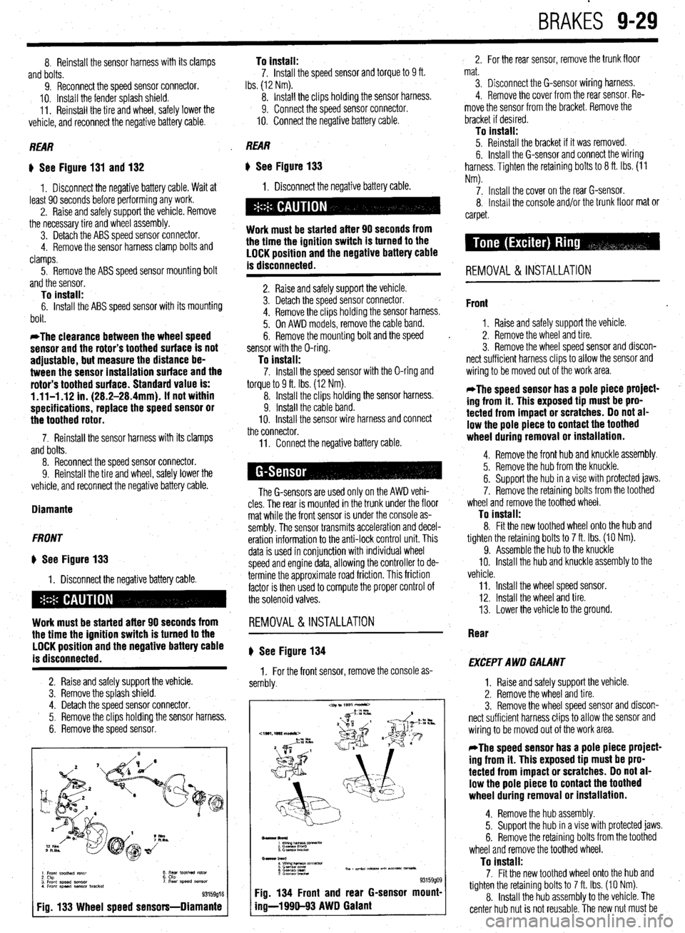
Fig. 133 Wheel speed sensors-Diamante
11. Connect the negative battery cable.
The G-sensors are used only on the AWD vehi-
cles. The rear is mounted in the trunk under the floor
mat while the front sensor is under the console as-
sembly. The sensor transmits acceleration and decel-
eration information to the anti-lock control unit. This
data is used in conjunction with individual wheel
speed and engine data, allowing the controller to de-
termine the approximate road friction. This friction
factor is then used to compute the proper control of
the solenoid valves.
REMOVAL&INSTALLATION
# See Figure 134
1. For the front sensor, remove the console as-
sembly.
-lkol*)
1 wimp--vx
2 Gasnan I‘m”0
3. Gmwor LmcM
Bmar burl
: wwzh&T&m~mm-
6 G.smsol Ired Th, - ape.24 m-5 un Nt- vmsa*.
7 c-.elwnbRcta
93159909 Fig. 134 Front and rear G-sensor mount-
ing-l 990-93 AWD Galant
2. For the rear sensor, remove the trunk floor
mat.
3. Disconnect the G-sensor wiring harness.
4. Remove the cover from the rear sensor. Re-
move the sensor from the bracket. Remove the
bracket if desired.
To install: 5. Reinstall the bracket if it was removed.
6. Install the G-sensor and connect the wiring
harness. Tighten the retaining bolts to 8 ft. Ibs. (11
Nm).
7. Install the cover on the rear G-sensor.
8, Install the console and/or the trunk floor mat or
carpet.
REMOVAL & INSTALLATION
Front
1. Raise and safely support the vehicle.
2. Remove the wheel and tire.
3. Remove the wheel speed sensor and discon-
nect sufficient harness clips to allow the sensor and
wiring to be moved out of the work area.
*The speed sensor has a pole piece project-
ing from it. This exposed tip must be pro-
tected from impact or scratches. Do not al-
low the pole piece to contact the toothed
wheel during removal or installation.
4. Remove the front hub and knuckle assembly.
5. Remove the hub from the knuckle.
6. Support the hub in a vise with protected jaws.
7. Remove the retaining bolts from the toothed
wheel and remove the toothed wheel.
To install: 8. Fit the new toothed wheel onto the hub and
tighten the retaining bolts to 7 ft. Ibs. (10 Nm).
9. Assemble the hub to the knuckle
IO. Install the hub and knuckle assembly to the
vehicle.
11. Install the wheel speed sensor.
12. Install the wheel and tire.
13. Lower the vehicle to the ground.
Rear
EXCEPT AWD GALANT
1. Raise and safely support the vehicle.
2. Remove the wheel and tire.
3. Remove the wheel speed sensor and discon-
nect sufficient harness clips to allow the sensor and
wiring to be moved out of the work area.
*The speed sensor has a pole piece project-
ing from it. This exposed tip must be pro-
tected from impact or scratches. Do not al-
low the pole piece to contact the toothed
wheel during removal or installation.
4. Remove the hub assembly.
5. Support the hub in a vise with protected jaws.
6. Remove the retaining bolts from the toothed
wheel and remove the toothed wheel.
To install: 7. Fit the new toothed wheel onto the hub and
tighten the retaining bolts to 7 ft. Ibs. (10 Nm).
8. Install the hub assembly to the vehicle. The
center hub nut is not reusable. The new nut must be
Page 375 of 408
BODYANDTRIM IO-7
1. Ashtray
2 cenrer DaneI
3. Sunglass pocket
4 Side panel assembly
5 Knee protector assembly (L
6 Hood lock release handle
7 Column cover. lower
8 Column cover. upper
9 Radio
10 Striker
11. Glove box assembly
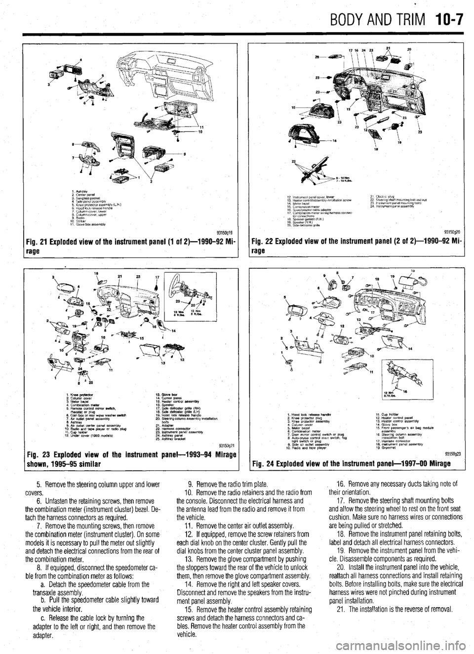
Fig. 21 Exploded view of the instrument panel (1 of 2)-1990-92 Mi-
rage
1. Knee pmtector
2. Column cover
3. Meter bezel
4. Combination meter
5. Remote control mirror switch.
rhsostat or plug
6. Coin box or rear wper washer switch
7. Aw outlet panel assembly
6. Ashtray
0. Air outlet center panel assembly
10. Radio and tape player or radio plug
11. Cup holder
12. Under COW (1993 models) 14. Comer panel
15. Heater control assembly %.
16. Speaker
17. Side defroster grille (RH)
16. Side defroster grille (LH)
19. Hood lock release handle
20. Ee$ng column assembly mstallation
21. Adapter
22 Harness oonnector
23. Instrument panel assembly
24. Ashtray panel
25. Ashtray bracket
9315og21 Fig. 23 Exploded view of the instrument panel-1993-94 Mirage
shown, 1995-95 similar
5. Remove the steering column upper and lower
covers.
6. Unfasten the retaining screws, then remove
the combination meter (instrument cluster) bezel. De-
tach the harness connectors as required.
7. Remove the mounting screws, then remove
the combination meter (instrument cluster). On some
models it is necessary to pull the meter out slightly
and detach the electrical connections from the rear of
the combination meter.
8. If equipped, disconnect the speedometer ca-
ble from the combination meter as follows:
a. Detach the speedometer cable from the
transaxle assembly.
b. Pull the speedometer cable slightly toward
the vehicle interior.
c. Release the cable lock by turning the
adapter to the left or right, and then remove the
adapter.
18
S-14Nm
7-lOh.lbs.
12 ln~v~rnent panel cover. lower
13 Hearer control assembly w,tallatlon screw
14 Meter bezel
15 Combination meter
16 Speedometer cable adapter
17 Comblnawn meterwr~ng harness connec-
. to1 co”“ectlo”s
16 Speaker amlsh (R H )
19 Speaker RHI e
20 S\de defroster grllla 21 Clock 01 plug
22 Steering shaft mount,ng bolt and nut
23 Ins!rument panel mounting bolts
24 Instrument panel assembly
9315og20 Fig. 22 Exploded view of the instrument panel (2 of 2)-1990-92 Mi-
rage
Fig. 24
1. Hood lock release handle
2. Knee protactor plug
3. Knee protector assembly
4 Column cover
5. Meter bezel
6. Combination meter
7. Door mrror control swich or plug
6. Auto-CNISO control mam swtch. fog
hght swtch M plug
0. Stde av outlet assembly
10 Radio and tape player 11. Cup holder
12. Heater control panel
13. Heater control assembly
14. Glove box
15 Front passenger’s 81, bag module
assembly
16. Steerq column assembly
lnstallatlon bon
17. Harness connector
16. Instrument panel assembly
19 Grommet
Exploded view of the instrument panel-l 997-00 Mirage
9. Remove the radio trim plate.
IO. Remove the radio retainers and the radio from
the console. Disconnect the electrical harness and
the antenna lead from the radio and remove it from
the vehicle.
11. Remove the center air outlet assembly.
12. If equipped, remove the screw retainers from
each dial knob on the center cluster. Gently pull the
dial knobs from the center cluster panel assembly.
13. Remove the glove compartment by pushing
the stoppers toward the rear of the vehicle to unlock
them, then remove the glove compartment assembly.
14. Remove the right and left speaker covers.
Disconnect and remove the speakers from the instru-
ment panel assembly.
15. Remove the heater control assembly retaining
screws and detach the harness connectors and ca-
bles. Remove the heater control assembly from the
vehicle. , 16. Remove any necessary ducts taking note of
their orientation,
17. Remove the steering shaft mounting bolts
and allow the steering wheel to rest on the front seat
cushion, Make sure no harness wires or connections
are being pulled or stretched.
18. Remove the instrument panel retaining bolts,
label and detach all electrical harness connectors.
19. Remove the instrument panel from the vehi-
cle. Disassemble components as required.
20. Install the instrument panel into the vehicle,
reattach all harness connections and install retaining
bolts. Before installing bolts, make sure the electrical
harness wires were not pinched during instrument
panel installation.
21. The installation is the reverse of removal.