1900 MITSUBISHI DIAMANTE steering wheel adjustment
[x] Cancel search: steering wheel adjustmentPage 289 of 408
7-10 DRIVETRAIN
The automatic transaxle allows engine torque and
power to be transmitted to the front wheels within a
narrow range of engine operating speeds. It will allow
the engine to turn fast enough to produce plenty of
power and torque at very low speeds, while keeping it
at a sensible rpm at high vehicle speeds (and it does
this job without driver assistance). The transaxle uses
a light fluid as the medium for the transmission of
power. This fluid also works in ths operation of vari-
ous hydraulic control circuits and as a lubricant. Be-
cause the transaxle fluid performs all of these func-
tions, trouble within the unit can easily travel from one
part to another For this reason, and because of the
complexity and unusual operating principles of the
transaxle, a very sound understanding of the basic
principles of operation will simplify troubleshooting
REMOVAL &INSTALLATION
Pan removal, fluid and filter
in Section 1 of this manual changes are covered
REMOVAL &INSTALLATION
1990-97 Mirage and 1990-93 Galant
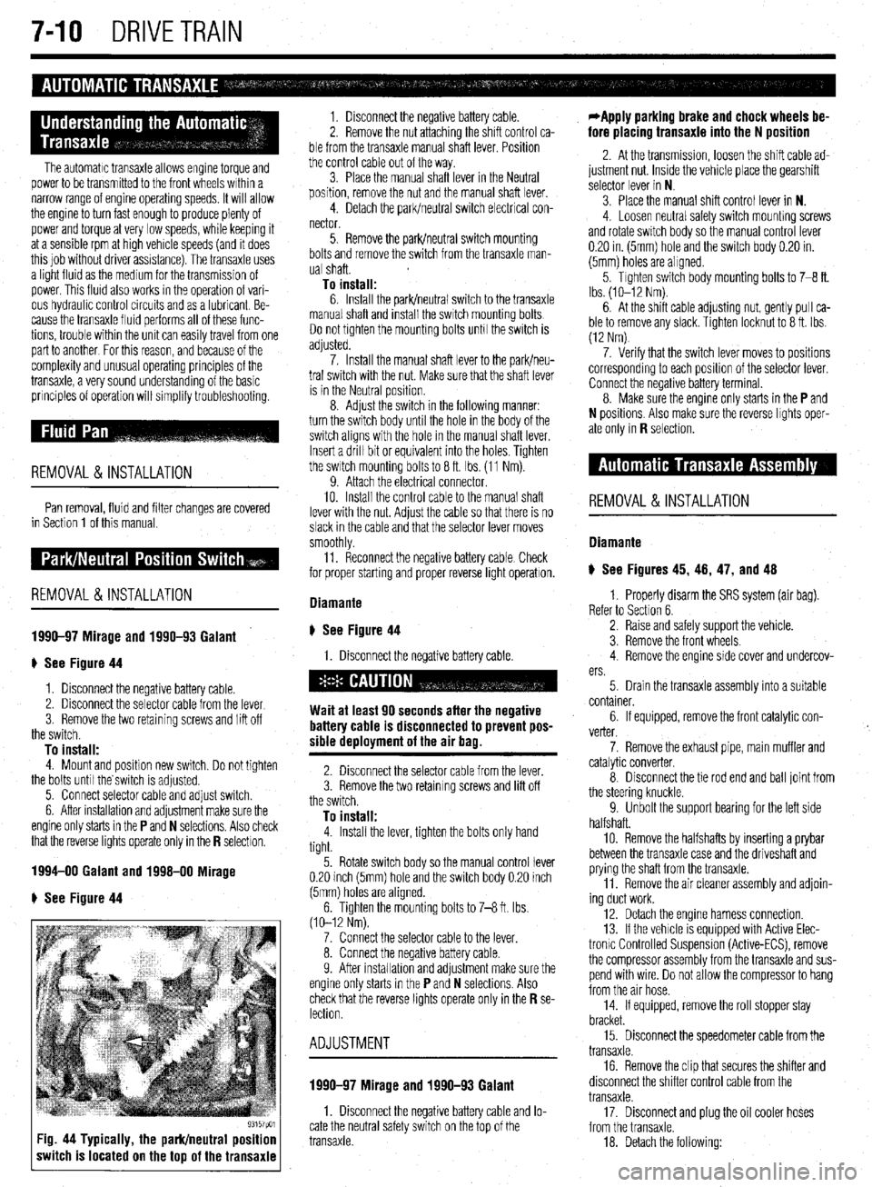
# See Figure 44
1. Disconnect the negative battery cable.
2. Disconnect the selector cable from the lever
3. Remove the two retaining screws and lift off
the switch.
To install: 4. Mount and position new switch. Do not tighten
the bolts until the switch is adjusted.
5. Connect selector cable and adjust switch.
6. After installation and adjustment make sure the
engine only starts in the
P and N selections. Also check
that the reverse lights operate only in the R selectlon.
1994-00 Galant and 1998-00 Mirage
e See Figure 44
93157pm Fig. 44 Typically, the park/neutral position
switch is located on the top of the transaxle
1. Disconnect the negative battery cable.
2. Remove the nut attaching the shift control ca-
ble from the transaxle manual shaft lever. Position
the control cable out of the way.
3. Place the manual shaft lever in the Neutral
position, remove the nut and the manual shaft lever.
4. Detach the park/neutral switch electrical con-
nector.
5. Remove the park/neutral switch mounting
bolts and remove the switch from the transaxle man-
ual shaft.
To install: 6. Install the park/neutral switch to the transaxle
manual shaft and install the switch mounting bolts
Do not tighten the mounting bolts unh the switch is
adjusted.
7. Install the manual shaft lever to the park/neu-
tral switch with the nut. Make sure that the shaft lever
is in the Neutral position.
8. Adjust the switch in the following manner:
turn the switch body until the hole in the body of the
switch aligns with the hole in the manual shaft lever.
Insert a drill bit or equivalent into the holes. Tighten
the switch mounting bolts to 8 ft. Ibs. (11 Nm).
9. Attach the electrical connector.
10. Install the control cable to the manual shaft
lever with the nut. Adjust the cable so that there is no
slack in the cable and that the selector lever moves
smoothly
11. Reconnect the negative battery cable Check
for proper starting and proper reverse light operatron.
Diamante
ti See Figure 44
1. Disconnect the negative battery cable.
Wait at least 90 seconds after the negative
battery cable is disconnected to prevent pos-
sible deployment of the air bag.
2. Disconnect the selector cable from the lever.
3. Remove the two retaining screws and lift off
the switch.
To install: 4. Install the lever, tighten the bolts only hand
tight.
5. Rotate switch body so the manual control lever
0.20 inch (5mm) hole and the switch body 0.20 inch
(5mm) holes are aligned.
6. Tighten the mounting bolts to 7-8 ft. Ibs.
(10-12 Nm).
7. Connect the selector cable to the lever.
8. Connect the negative battery cable.
9. After installahon and adjustment make sure the
engine only starts in the
P and N selections. Also
check that the reverse lights operate only in the R se- lection.
ADJUSTMENT
1990-97 Mirage and 1990-93 Galant
1. Disconnect the negative battery cable and lo-
cate the neutral safety switch on the top of the
transaxle.
*Apply parking brake and chock wheels be-
fore placing transaxle into the N position
2. At the transmission, loosen the shift cable ad-
justment nut. Inside the vehicle place the gearshift
selector lever in N
3. Place the manual shift control lever in N.
4. Loosen neutral safety switch mounhng screws
and rotate switch body so the manual control lever
0.20 in. (5mm) hole and the switch body 0.20 in.
(5mm) holes are aligned.
5. Tighten switch body mounting bolts to 7-8 ft.
Ibs. (lo-12 Nm).
6. At the shift cable adjusting nut, gently pull ca-
ble to remove any slack. Tighten locknut to 8 ft. Ibs.
(12 Nm)
7. Verify that the switch lever moves to positions
corresponding to each position of the selector lever.
Connect the negative battery terminal.
8. Make sure the engine only starts in the
P and
N positions. Also make sure the reverse lights oper-
ate only in
R selection.
REMOVAL&INSTALLATION
Diamante
) See Figures 45, 46, 47, and 48
1. Properly disarm the SRS system (air bag).
Refer to Section 6.
2. Raise and safely support the vehicle.
3. Remove the front wheels.
4. Remove the engine side cover and undercov-
ers.
5. Drain the transaxle assembly into a suitable
container.
6. If equipped, remove the front catalytic con-
verter.
7. Remove the exhaust pipe, main muffler and
catalytic converter.
8. Disconnect the tie rod end and ball joint from
the steering knuckle.
9. Unbolt the support bearing for the left side
halfshaft.
10. Remove the halfshafts by inserting a prybar
between the transaxle case and the driveshaft and
prying the shaft from the transaxle.
11. Remove the air cleaner assembly and adjoin-
ing duct work.
12. Detach the engine harness connection.
13. If the vehicle is equipped with Active Elec-
tronlc Controlled Suspension (Active-ECS), remove
the compressor assembly from the transaxle and sus-
pend with wire. Do not allow the compressor to hang
from the air hose.
14. If equipped, remove the roll stopper stay
bracket.
15. Disconnect the speedometer cable from the
transaxle.
16. Remove the clip that secures the shifter and
disconnect the shifter control cable from the
transaxle.
17. Disconnect and plug the oil cooler hoses
from the transaxle.
18. Detach the following:
Page 292 of 408
DRIVETRAIN 7-13
27. Shde the transaxle rearward and carefully
lower it from the vehicle.
To install: 28. After the torque converter has been mounted
on the transaxle, install the transaxle assembly to the
engine. Install the mounting bolts and tighten to 35
ft. Ibs. (48 Nm).
29. Install the transaxle lower coupling bolt and
tighten to 21-25 ft Ibs. (29-34 Nm).
30. Connect the torque converter to the flexplate
and tighten the bolts to 33-38 ft. Ibs. (45-52 Nm).
31. Install the cover to the transaxle bellhous-
ing and tighten the mounting bolts to 7 ft. Ibs. (9
Nm).
32 Install the crossmember and tighten the front
mounting bolts to 65 ft. Ibs (88 Nm) and the rear
bolt to 54 ft. Ibs. (73 Nm) Install the front engine roll
stopper through-bolt and lightly tighten. Once the full
weight of the engine is on the mounts, tighten the ’
bolt to 42 ft. Ibs. (57 Nm),
33. Install the triangular stay bracket and tighten
the mounting bolts to 65 ft. Ibs. (88 Nm).
34. Install the halfshafts, using new circlips on
the axle ends.
When installing the axleshaft, keep the in-
board joint straight in relation to the axle, so
as not to damage the oil seal lip of the
transaxle with the serrated part of the half-
shaft.
35. Connect the tie rod and ball joints to the
steering knuckle. Tighten the ball joint self-locking
nuts to 48 ft. Ibs. (65 Nm). Tighten the tie rod end nut
to 21 ft. Ibs. (28 Nm) and secure with a new cotter
pin.
36. Connect the damper fork to the lower control
arm and tighten the through-bolt to 65 ft Ibs. (88
Nm).
37. Connect the stabilizer link to the damper fork,
and tighten the self-locking nut to 29 ft. Ibs. (39 Nm).
38. Install the undercover.
39. Install the wheels and carefully lower the ve-
hicle
40. Install the transaxle mount bracket to the
transaxle, and tighten the mounting nuts to 32 ft. Ibs.
(43 Nm).
41. Install the rear roll stopper mounting bracket.
42. Remove the engine support. Tighten the
transaxle mount through-bolt to 51 ft. Ibs. (69 Nm)
and tighten the front engine roll stopper through-bolt.
43. Install the upper transaxle mounting bolts
and tighten to 35 fl. Ibs. (48 Nm).
44. Install the starter motor.
45. Install the dipstick tube and the dipstick
46. Install the shifter cable mounting bracket.
47. Connect the shifter lever and tighten the re-
taining nut to 14 ft. Ibs. (19 Nm).
48. Connect the oil cooler lines and secure with
clamps.
49. Attach the electrical connectors for the
speedometer, solenoid, neutral safety switch (in-,
hibitor switch), the pulse generator, kickdown servo
switch and oil temperature sensor.
50. Install the air cleaner and the air intake hose.
51. Connect the negative battery cable.
52. Make sure the vehicle is level, and refill the
transaxle. Start the engine and allow to idle for 2 minutes. Apply parking brake and move selector
through each gear position, ending in N. Recheck
fluid level and add if necessary. Fluid level should be
between the marks in the HOT range.
53. Check the transaxle for proper operation.
Make sure the reverse lights come on when in re-
verse and the engine starts only in
P or N.
Mirage
*If the vehicle is going to be rolled on its
wheels while the halfshafts are out of the ve-
hicle, obtain two outer CV-joints or proper
equivalent tools and install to the hubs. If the
vehicle is rolled without the proper torque
applied to the front wheel bearings, the bear-
ings will no longer be usable.
1. Disconnect the negative battery cable then
the positive battery cable.
2. Remove the battery and battery tray.
3. Remove the air hose and air cleaner assem-
bly.
4. Raise the vehicle and support safely.
5. Remove the under guard pan.
6. Drain the transaxle oil into a suitable con-
tainer.
7. If equipped with 1.6L engine, remove the ten-
sion rod.
8. Disconnect the control cable and cooler
lines.
9. On 3-speed transaxles, disconnect the throt-
tle control cable.
10. On 4-speed transaxles, perform the following:
a. Detach the shift control solenoid valve
connector.
b. Disconnect the inhibitor switch and kick-
down servo switch.
c. Disconnect the pulse generator and oil
temperature sensor.
11. Disconnect the speedometer cable and re-
move the starter.
12. Remove the transaxle mounting bolts and
bracket.
13. Disconnect the stabilizer bar from the lower
control arm.
14. Disconnect the steering tie rod end and the
ball joint from the steering arm.
15. Remove the halfshafts at the inboard side
from the transaxle. Tie the joint assembly aside.
*It is not necessary to disconnect the half-
shafts from the wheel hubs.
16. Support the engine and remove the center
member.
17. Remove the bellhousing cover and remove
the driveplate bolts.
18 Remove the transaxle assembly lower con-
necting bolt, located just over the halfshaft opening.
19. Properly support the transaxle assembly, then
lower it, moving it to the right for clearance.
To install: 20. After the torque converter has been mounted
on the transaxle, install the transaxle assembly on the
engine. Install the mounting bolts and tighten to
31-40 ft. Ibs. (43-55 Nm) on 1990-92 models and
35 ft. Ibs. (48 Nm) on 1993-00 models.
21. Tighten the driveplate bolts to 33-38 ft. Ibs.
(46-53 Nm). Install the bellhousing cover.
22. Install the center member. 23. Replace the circlips and install the halfshafts
to the transaxle.
24. Install the tie rods, ball joints and stabilizer
links to the steering arm
25. Install the transaxle mounting bracket and
bolts.
26. Install the starter.
27. Connect the speedometer cable.
28. Connect the inhibitor switch, kickdown servo
switch, the pulse generator and oil temperature sen-
sor, if disconnected.
29. Connect the shift control solenoid valve con-
nector.
30. Connect the control cables and oil cooler
lines.
31. Install the tension rod, if removed.
32. Install the air cleaner assembly.
33. Install the battery tray and battery.
34. Connect the positive then the negative termi-
nal.
35. Refill with Dexron@ II, Mopar ATF Plus type
7176 or equivalent, automatic transaxle fluid.
36. Start the engine and allow to idle for two min-
utes. Apply parking brake and move selector through
each gear position, ending in N. Recheck fluid level
and add if necessary. Fluid level should be between
the marks in the HOT range.
ADJUSTMENTS
Shifter Control Cable Adjustment
1. The shifter cable adjustment is done at the
neutral safety switch (inhibitor switch). Locate the
switch on the transaxle and note the alignment holes
in the arm and the body of the switch. Place the se-
lector lever in N. Place the manual lever of the
transaxle in the neutral position.
2. Check alignment of the hole in the manual
control lever to the hole in the inhibitor switch body.
If the holes do not align, adjustment is required.
3. To adjust, loosen the nut on the cable end and
pull the cable end by hand until the alignment holes
match. Tighten the nut. Check that the transaxle
shifts and conforms to the positions of the selector
lever.
Throttle Valve Cable
The throttle valve adjustment applies only to the
1990-96 Mirage.
1. Place selector lever and manual control lever
in N position.
2. Loosen adjusting nut. While lightly pulling on
control cable tighten mounting nut to 7-10 ft. Ibs.
(X-14 Nm).
3. When adjustment is complete, be sure selector
lever is still in the N position. Verify all functions
correspond to the position indicated on the selector
lever.
The halfshaft removal and installation and over-
haul are the same as a manual transaxle Please refer
to Manual Transaxle in this Section
Page 296 of 408
WHEELS 8-2
WHEEL ASSEMBLY 8-2
REMOVAL & INSTALLATION 8-2
INSPECTION 8-2
WHEELLUG STUDS 8-2
REMOVAL & INSTALLATION 8-2
FRONT SUSPENSION 8-4
MACPHERSONSTRUTAND COIL
SPRING 8-7
REMOVAL & INSTALLATION 8-7
OVERHAUL 8-7
SHOCKABSORBERAND COIL
SPRING 8-8
REMOVAL &INSTALLATION 8-8
OVERHAUL 8-9
UPPER BALLJOINT 8-9
REMOVAL & INSTALLATION 8-9
INSPECTION 8-9
UPPER CONTROLARM 8-10
REMOVAL &INSTALLATION 8-10
LOWER BALLJOINT 8-10
REMOVAL &INSTALLATION 8-10
INSPECTION 8-10
LOWER CONTROL ARM 8-10
REMOVAL&INSTALLATION 8-10
SWAY BAR 8-12
REMOVAL & INSTALLATION 8-12
KNUCKLE, HUB, AND BEARING 8-13
REMOVAL & INSTALLATION 8-13
WHEEL ALIGNMENT 8-16
CASTER 8-16
CAMBER 8-17
TOE 8-17
REAR SUSPENSION 8-18
STRUT AND COIL SPRING 8-21
REMOVAL & INSTALLATION 8-21
OVERHAUL 8-22
UPPER CONTROLARMS 8-22
REMOVAL & INSTALLATION 8-22
LOWER CONTROL ARMS 8-23
REMOVAL &INSTALLATION 8-23
TRAINING ARM 8-24
REMOVAL & INSTALLATION 8-24
SWAY BAR 8-25
REMOVAL &INSTALLATION 8-25
HUB & BEARINGS 8-25
ADJUSTMENT 8-25
REMOVAL & INSTALLATION 8-25
STEERING 8-27
STEERING WHEEL 8-27
REMOVAL &INSTALLATION 8-27
COMBINATION SWITCH 8-29
REMOVAL &INSTALLATION 8-29
WINDSHIELD WIPER SWITCH 8-29
REMOVAL&INSTALLATION 8-29
IGNITION LOCK CYLINDER 8-29 '
REMOVAL &INSTALLATION 8-29
IGNITION SWITCH 8-30
REMOVAL &INSTALLATION 8-30
STEERING LINKAGE 8-30
REMOVAL&INSTALLATION 8-30
MANUAL RACK AND PINION STEERING
GEAR 8-31 REMOVAL & INSTALLATION 8-31
POWER RACK AND PINION STEERING
GEAR 8-32
REMOVAL &INSTALLATION 8-32
POWERSTEERING PUMP 8-34
REMOVAL &INSTALLATION 8-34
SYSTEM BLEEDING 8-36
COMPONENT LOCATIONS
FRONTSUSPENSION COMPONENT
LOCATIONS 8-4
REARSUSPENSION COMPONENT
LOCATIONS 8-18
SPECIFICATIONS CHARTS ’
TORQUE SPECIFICATIONS 8-39
Page 298 of 408
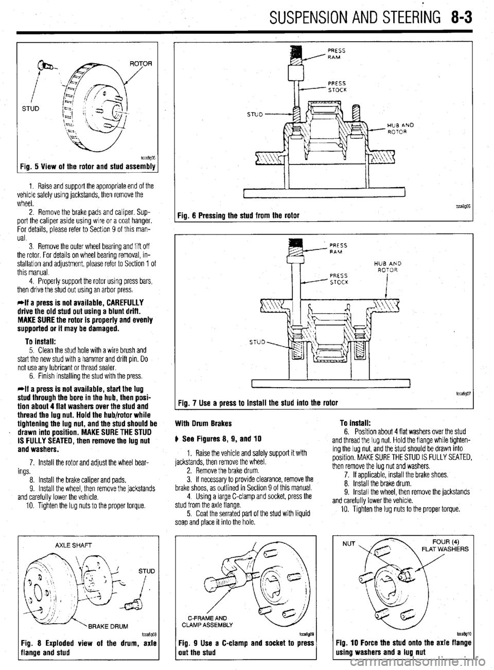
SUSPENSION AND STEERiNG 8-3
STUD
Fig. 5 View of the rotor and stud assembly
1. Raise and support the appropriate end of the
vehicle safely using jackstands, then remove the
wheel.
2. Remove the brake pads and caliper. Sup-
port the caliper aside using wire or a coat hanger.
For details, please refer to Section 9 of this man-
ual.
3 Remove the outer wheel bearing
and liff off
the rotor. For details on wheel bearing removal, in-
stallation and adjustment, please refer to Section 1 of
this manual.
4. Properly support the rotor using press bars,
then drive the stud out using an arbor press.
*If a press is not available, CAREFULLY
drive the old stud out using a blunt drift.
MAKE SURE the rotor is properly and evenly
supported or it may be damaged.
To install:
5. Clean the stud hole with a wire brush and
start the new stud with a hammer and drift pin. Do
not use any lubricant or thread sealer.
6. Finish installing the stud with the press.
*If a press is not available, start the lug
stud through the bore in the hub, then posi-
tion about 4 flat washers over the stud and
thread the lug nut. Hold the hub/rotor while
tightening the lug nut, and the stud should be
drawn into position. MAKE SURE THE STUD
IS FULLY SEATED, then remove the lug nut
and washers.
7. Install the rotor and adjust the wheel bear-
ings
8. Install the brake caliper and pads.
9. Install the wheel, then remove the jackstands
and carefully lower the vehicle.
10. Tighten the lug nuts to the proper torque.
AXLE SHAFT
Im3goa
3g. 8 Exploded view of the drum, axle
lange and stud
PRESS RAM
PRESS
STOCK
Fig. 6 Pressing the stud from the rotor
tcca$Oi Fig. 7 Use a press to install the stud into the rotor
With Drum Brakes To install:
6. Position about 4 flat washers over the stud p See Figures 8, 9, and 10
1. Raise the vehicle and safely support it with
jackstands, then remove the wheel.
2. Remove the brake drum.
3. If necessary to provide clearance, remove the
brake shoes, as outlined in Section 9 of this manual.
4. Using a large C-clamp and socket, press the
stud from the axle flange.
5. Coat the serrated part of the stud with liquid
soap and place it into the hole. and thread the lug nut. Hold the flange while tighten-
ing the lug nut, and the stud should be drawn into
position. MAKE SURE THE STUD IS FULLY SEATED,
then remove the lug nut and washers.
7. If applicable, install the brake shoes.
8. Install the brake drum.
9. Install the wheel. then remove the iackstands
and carefully lower the vehicle.
10. Tighten the lug nuts to the proper torque.
C-FRAME AND
CLAMP ASSEMBLY
Fig. 9 Use a C-clamp and socket to press
out the stud
NUT FLAT WASHERS
Fig. 10 Force the stud onto the axle flange
using washers and a lug nut
Page 320 of 408
SUSPENSION AND STEERING 8-25
1994-00 Galant and 1997-00 Diamante
4. Remove the retainer bolts and the stabilizer
..- 8, Loosely in”,“,, +I?,, r+&,il;7nr kn- h.~r.l,,d” -..
1. Raise and safely support the vehicle securely he bushing.
the vehicle.
on jackstands.
7er hnr with FI wmnph Remnun (1 Alinn th
2. Remove the wheel and tire assembly.
3. Support the rear axle using a jack or other
suitable device.
4. Remove the trailing arm-to-knuckle connec-
tion,
5. Remove the trailing arm-to-body mounting
n~~““yll-““!~ (1II” fWll”“C LllG llcllllll$j a,,,,. To install:
6. Install the trailing arm and install the trailing
arm-to-body mounting through-bolt. Tighten the bolt
to 99-114 ft. Ibs. (137-157 Nm).
7. Install the trailing arm-to-knuckle connection. Dar brackets. Hemove t
5. Hold the stabilL_. __. . . _ . .._..“... ..I . .._._
the self-locking nut.
6. Once the stabilizer bar nut is removed, re-
move the joint cups and stabilizer rubber bushing.
7. Hold the stabilizer link with a wrench and re-
move the self-locking nuts. Remove the stabilizer
link.
8. Lower the jack supporting the rear axle
in a slight gap between the rear sus-
? body of the vehicle.
! the stabilizer bar.
IL_ L__ I__ _)----- .-- .-J JAI.... slightly. Mainta
pension and thf
9. Remow
10. Inspect LIIB uar 101 uamage, wear ana aereno-
ration and replace as required.
-Fe c--a-...
1 IIIJMII UK 3La”III‘w “ill “lduKm “II
“. , ,,LY,, ,,ie side locating markings on the stabi-
lizer bar, so that the marking on the bar extends ap-
proximately 0.39 inches (1Omm) from the outer edge
of the mounting bracket, on both sides.
10. With the stabilizer bar properly aligned,
tighten the mounting bracket bolts to 28 ft. Ibs. (39
Nm).
11. Connect the stabilizer links to the damper fork
andihe stabilizer bar. Tighten the locking nuts to 28
ft. Ibs. (38 Nm).
12. Lower the vehicle and connect the negative
8.. Ia
mery came.
Tighten the bolt to 85-99 ft. Ibs. (118-137 Nm).
nemove me axle suppon
9. Install the wheel and tire
10. Lower the vehicle. aewce.
assembly.
I 0 Insran: 11, Install the stabilizer bar into the vehicle. Raise
the rear axle and suspension into place.
12. Install the stabilizer link into the stabilizer ba
Ir
ADJUSTMENT anfi indc4ll 33 ft. Ibs. (45 Nm).
13. Install the ioint __-_ _.._ __
1. Raise and safely support the vehicle securely the link. Ins’
..I.,
Mlhiln hnlrii, tall a rkW self~locking n
lll~llG llUlulng the stabi” ” ’ ’ ’
wrench, tighten the self,
of the stabilizer link is v
ihe hub and bearing assembly.
5. Support the rear axle using a jack or other
suitable device.
6. Remove the lower shock absorber-to-trailing
arm connection. ocking nut. Tighten the nut to
ClrnC 2nd ?$bilizer rubber to
ut onto the link.
nzer nnK oall studs with a
-locking nut so the protrusion
within 0.354-0.433 in.
I stabilizer bar bushings,
>+nn thn hnk In -I A u (9-llmm).
14. Install the cente
brackets and bolts. Tiqt Mirage
*Never disassemble the rear hub bearing.
The wheel bearing is serviced by replace-
ment of the hub.
1. Raise and safely support the vehicle.
2. Remove the rear wheel.
3. Remove the caliper and brake disc of brake 1992-96 biamante
on IacKsranos.
2. Remove the wheel and tire assembly
3, Remove thn hralm rntnr 4. Remove1
7. Remove the stabilizer bar link-to-trailing arm
connection.
8. Remove the tie rod end-to-trailing arm con-
nection.
9. Remove the lower control arm-to-trailing arm
connection.
10. Remove the trailing arm-to-body mounting
through-bolt and remove the trailing arm. Nm).
15. Install the parking
sensor installation bolt.
, , I oraxe cat * ale ar
member bracket and tighten
i Nm). Tighten the crossmem-
A to 94 ft. Ibs. (130 Nm). 16. Install the cross
the bolt to 61 ft. Ibs. (8!
ber bracket mounting nl
17. Install the rubbe
locking nuts onto the cro:
the nuts to 80-94 fl. Ibs. (
18. Lower the vehicle. id rear speed drum.
4. Remove the dust cab and tighten the flange ll”, *lb+ to 130 ft. Ibs. (180 Nm).
5. Using a dial indicator, measure wheel bear-
!r insulators and new seif-
ismemoer ’ brackets. Tighten
[110-130 Nm). ing end-play. The maximum limit for end-play is
o.oc-- ‘^ -- rzu mcnes (u.usmm).
arol
tanc
sisk 6. Using a spring scale and a rope wrapped
md the bolts, measure the rotary sliding resis-
e of the bearing/hub. The maximum limit for re-
mce is 4 Ibs. (19 N).
7. If any of the readings exceed the specifica-
To install:
11. Install the trailing arm and install the trailina Diamante and 1994-98 Gal&i
t tions, replacement of the hub is required.
8. Install the dust cap.
9. Install the brake disc and caliper, or brake
negative battery ( sble.
;“I,-.
I support the vbhlblG.
stabilizer links by removing
Alizer bar mounting brackets
from the vehicle.
lonents for wear or damage,
ded. drum.
10. Install the rear wheel assembly and lower the
vehicle to the floor.
*
1990-93 Galant
*Vehicles equipped with rear disc brakes
use a sealed hub and bearing assembly,
which requires no adjustment. Drum brake
models are
adjusted using the following pro- arm-to-body mounting through-bolt. Tighten the bolt
to 101-116 ft. Ibs. (140-160 Nm). ) See Figure 72
12. Install the trailing arm-to-lower control arm
1. Disconnect the I
connection. Tighten the bolt to 101-116 ft. Ibs.
(140-160 Nm). 2. Raise and safely
13. Install the tie rod end-to-trailing arm connec- 3. Disconnect the I
tion. Tighten the nut to 21 ft. Ibs. (29 Nm). the self-locking nuts.
14. Install the stabilizer bar link-to-trailing arm 4. Remove the stat
connection. Tighten the nut to 29 ft. Ibs. (40 Nm). and bushings.
15. Install the lower shock absorber-to-trailing
5. Remove the bar
arm connection. Tighten the bolt to 65 ft. Ibs. (90 6. Inspect all comr
. and replace parts as nee
Nrn).
16. Remove the axle support device.
17. Install the hub and bkaring assembly,
18. Install the brake rotor.
19. Install the wheel and tire assembly.
20. Lower the vehicle.
REMOVALANDINSTALLATION
1990-93 Gaiant
1. Raise and support the vehicle safely.
2. Place a jack under the rear axle and suspen- To install:
7 InstA the dnhili cedure. ._._ . . .._ -.--.. lzer bar into the vehicle.
1. Raise the vehicle and support it safely.
2. Remove the wheel and tire assemblies.
3. If equipped with rear disc brakes, remove the
caliper assembly.
4. Remove the grease cap and the hub nut.
5. Tighten the wheel bearing nut to 20 ft. Ibs. (27
Nm) while rotatir ” ”
6. Back off th
load and then tighten it to 7 ft. Ibs. (10 Nm).
7. Install the nut lock and a new cotter pin.
8. If brake caliper was removed, reinstall.
9. Install the wheel and lower the vehicle.
Diamante and lQQ44 Galant 10 tne mum/hub.
ie adjusting nut to remove the pre-
Sian assembly.
3. Remove the self-locking nuts and crossmem-
ber bracket.
93158P61 Fig. 72 Remove the self-locking nuts from Measure the wheel bearing end-play using a dial
the stabilizer bar link indicator. The end-play should be 0.002 inches
a (0.05mm) or less with the wheel bearing locknut
Page 321 of 408
SUSPENSION AND STEERING 8-25
1994-00 Galant and 1997-00 Diamante
1, Raise and safely support the vehicle securely
on jackstands.
2. Remove the wheel and tire assembly.
3. Support the rear axle using a jack or other
suitable device.
4. Remove the trailing arm-to-knuckle connec-
tion.
5. Remove the trailing arm-to-body mounting
through-bolt and remove the trailing arm.
To install: 6. Install the trailing arm and install the trailing
arm-to-body mounting through-bolt. Tighten the bolt
to 99-114 ft. lbs. (137-157 Nm).
7. Install the trailing arm-to-knuckle connection.
Tighten the bolt to 85-99 ft. Ibs. (118-137 Nm).
8. Remove the axle support device.
9. install the wheel and tire assembly.
10. Lower the vehicle.
1992-96 Diamante
1. Raise and safely support the vehicle securely
on jackstands.
2. Remove the wheel and tire assembly.
3. Remove the brake rotor.
4. Remove the hub and bearing assembly.
5. Support the rear axle using a jack or other
suitable device.
6. Remove the lower shock absorber-to-trailing
arm connection.
7. Remove the stabilizer bar link-to-trailing arm
connection.
8. Remove the tie rod end-to-trailing arm con-
nection.
9. Remove the lower control arm-to-trailing arm
connection.
10. Remove the trailing arm-to-body mounting
through-bolt and remove the trailing arm.
To install: 11, Install the trailing arm and install the trailing
arm-to-body mounting through-bolt. Tighten the bolt
to lOl-116ft. Ibs. (14C-160 Nm).
12. Install the trailing arm-to-lower control arm
connection. Tighten the bolt to 101-116 ft. Ibs.
(140-l 60 Nm).
13. Install the tie rod end-to-trailing arm connec-
tion. Tighten the nut to 21 ft. Ibs. (29 Nm).
14. Install the stabilizer bar link-to-trailina arm
connection. Tighten the nut to 29 ft. Ibs. (40 im).
15. Install the lower shock absorber-to-trailing
arm connection. Tighten the bolt to 65 ft. Ibs. (90
Nm).
16. Remove the axle support device.
17. Install the hub and bearing assembly.
18. Install the brake rotor.
19. Install the wheel and tire assembly.
20. Lower the vehicle.
REMOVALANDINSTALLATION '
1990-93 Galant
1. Raise and support the vehicle safely.
2. Place a jack under the rear axle and suspen-
sion assembly.
3. Remove the self-locking nuts and crossmem-
her bracket.
d.--- -.
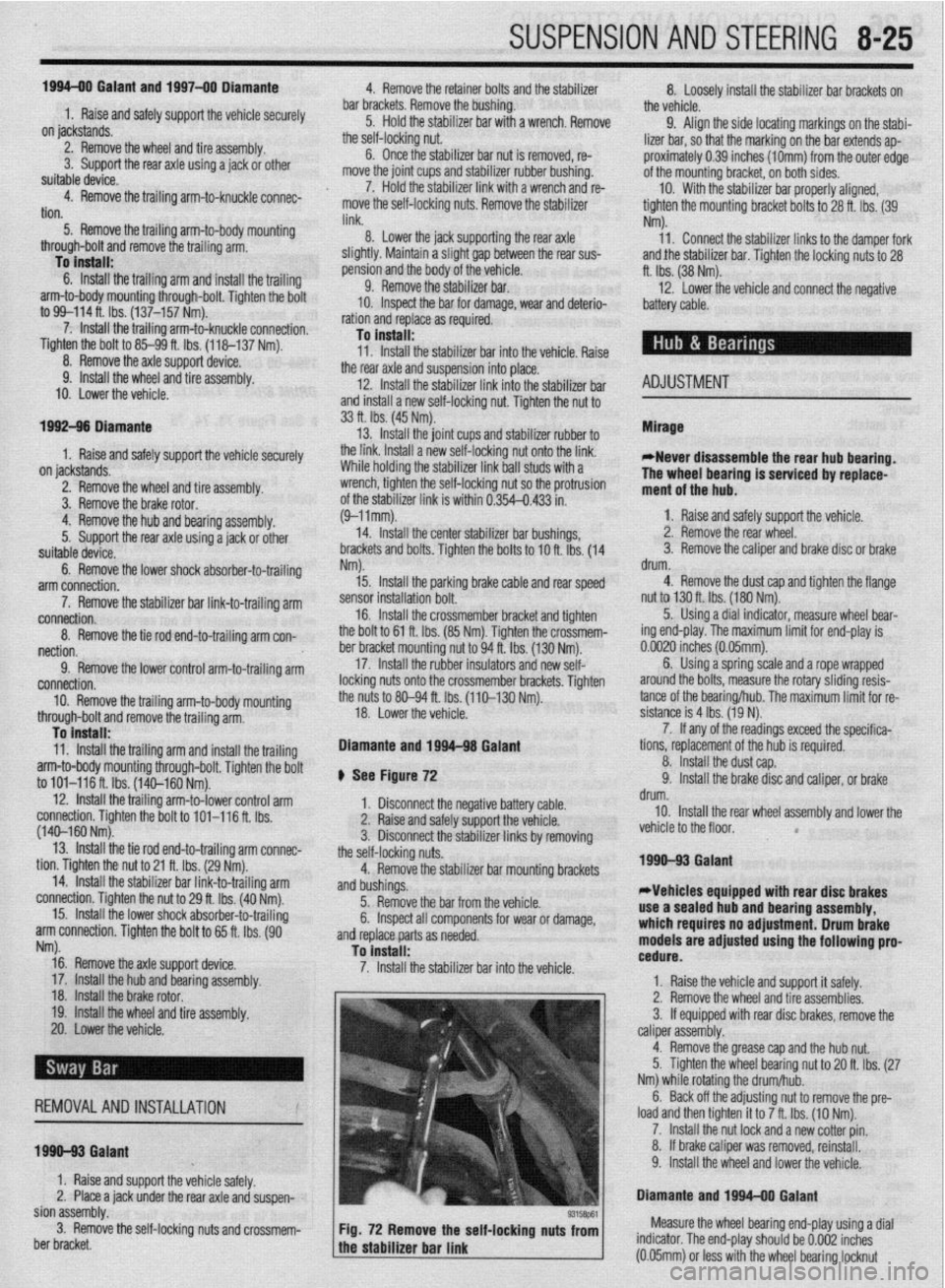
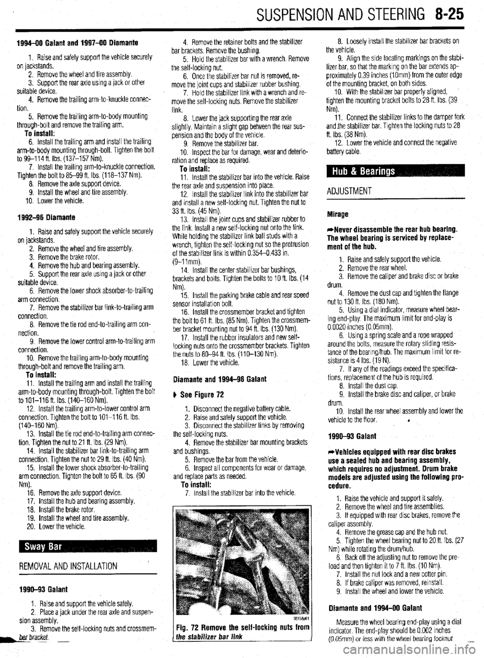
Fig. 72 Remove the self-locking nuts from
the stabilizer bar link 8. Loosely install the stabilizer bar brackets on
the vehicle.
9. Align the side locating markings on the stabi-
lizer bar, so that the marking on the bar extends ap-
proximately 0.39 inches (1Omm) from the outer edge
of the mounting bracket, on both sides.
10. With the stabilizer bar properly aligned,
tighten the mounting bracket bolts to 28 ft. Ibs. (39
Nm).
11. Connect the stabilizer links to the damper fork
andjhe stabilizer bar. Tighten the locking nuts to 28
ft. Ibs. (38 Nm).
12. Lower the vehicle and connect the negative
battery cable.
ADJUSTMENT
1990-93 Galant
*Vehicles equipped with rear disc brakes
use a sealed hub and bearing assembly,
which requires no adjustment. Drum brake
models are adjusted using the following pro-
cedure.
1. Raise the vehicle and support it safely.
2. Remove the wheel and tire assemblies.
3. If equipped with rear disc brakes, remove the
caliper assembly.
4. Remove the grease cap and the hub nut.
5. Tighten the wheel bearing nut to 20 ft. Ibs. (27
Nm) while rotating the drum/hub.
6. Back off the adjusting nut to remove the pre-
load and then tighten it to 7 ft. Ibs. (10 Nm).
7. Install the nut lock and a new cotter pin.
8. If brake caliper was removed, reinstall.
9. Install the wheel and lower the vehicle.
Diamante and 1994-00 Galant
Measure the wheel bearing end-play using a dial
indicator. The end-play should be 0.002 inches
(0.05mm) or less with the wheel bearing locknut _
Page 338 of 408
9-2 BRAKES
Hydraulic systems are used to actuate the brakes
of all modern automobiles. The system transports the
power required to force the frictional surfaces of the
braking system together from the pedal to the indi-
vidual brake units at each wheel. A hydraulic system
is used for two reasons.
First, fluid under pressure can be carried to all
parts of an automobile by small pipes and flexible
hoses without taking up a significant amount of room
or posing routing problems.
Second, a great mechanical advantage can be
given to the brake pedal end of the system, and the
foot pressure required to actuate the brakes can be
reduced by making the surface area of the master
cylinder pistons smaller than that of any of the pis-
tons in the wheel cylinders or calipers.
The master cylinder consists of a fluid reservoir
along with a double cylinder and piston assembly.
Double type master cylinders are designed to sepa-
rate the front and rear braking systems hydraulically
in case of a leak. The master cylinder converts me-
chanical motion from the pedal into hydraulic pres-
sure within the lines. This pressure is translated back
into mechanical motion at the wheels by either the
wheel cylinder (drum brakes) or the caliper (disc
brakes).
Steel lines carry the brake fluid to a point on the
vehicle’s frame near each of the vehicle’s wheels. The
fluid is then carried to the calipers and wheel cylin-
ders by flexible tubes in order to allow for suspen-
sion and steering movements.
In drum brake systems, each wheel cylinder con-
tains two pistons, one at either end, which push out-
ward in opposite directions and force the brake shoe
into contact with the drum.
In disc brake systems, the cylinders are part of the
calipers. At least one cylinder in each caliper is used
to force the brake pads against the disc.
All pistons employ some type of seal, usually
made of rubber, to minimize fluid leakage. A rubber
dust boot seals the outer end of the cylinder against
dust and dirt. The boot fits around the outer end of
the piston on disc brake calipers, and around the
brake actuating rod on wheel cylinders.
The hydraulic system operates as follows: When at
rest, the entire system, from the piston(s) in the mas-
ter cylinder to those in the wheel cylinders or
calipers, is full of brake fluid. Upon application of the
brake pedal, fluid trapped in front of the master cylin-
der piston(s) is forced through the lines to the wheel
cylinders. Here, it forces the pistons outward, in the
case of drum brakes, and inward toward the disc, in
the case of disc brakes. The motion of the pistons is
opposed by return springs mounted outside the
cylinders in drum brakes, and by spring seals, in disc
brakes.
Upon release of the brake pedal, a spring located
inside the master cylinder immediately returns the
master cylinder pistons to the normal position. The
pistons contain check valves and the master cylinder
I
has compensating ports drilled in it. These are un-
covered as the pistons reach their normal position.
The piston check valves allow fluid to flow toward the
wheel cylinders or calipers as the pistons withdraw.
Then, as the return springs force the brake pads or
shoes into the released position, the excess fluid
reservoir through the compensating ports. It is during the time the pedal is in the released position that any
fluid that has leaked out of the system will be re-
placed through the compensating ports.
Dual circuit master cylinders employ two pistons,
located one behind the other, in the same cylinder.
The primary piston is actuated directly by mechanical
linkage from the brake pedal through the power
booster. The secondary piston is actuated by fluid
trapped between the two pistons. If a leak develops in
front of the secondary piston, it moves forward until it
bottoms against the front of the master cylinder, and
the fluid trapped between the pistons will operate the
rear brakes. If the rear brakes develop a leak, the pri-
mary piston will move forward until direct contact
with the secondary piston takes place, and it will
force the secondary piston to actuate the front brakes.
In either case, the brake pedal moves farther when the
brakes are applied, and less braking power is avail-
able.
All dual circuit systems use a switch to warn the
driver when only half of the brake system is opera-
tional. This switch is usually located in a valve body
which is mounted on the firewall or the frame below
the master cylinder. A hydraulic piston receives pres-
sure from both circuits, each circuits pressure being
applied to one end of the piston. When the pressures
are in balance, the piston remains stationary. When
one circuit has a leak, however, the greater pressure
in that circuit during application of the brakes will
push the piston to one side, closing the switch and
activating the brake warning light.
In disc brake systems, this valve body also con-
tains a metering valve and, in some cases, a propor-
tioning valve. The metering valve keeps pressure
from traveling to the disc brakes on the front wheels
until the brake shoes on the rear wheels have con-
tacted the drums, ensuring that the front brakes will
never be used alone. The proportioning valve con-
trols the pressure to the rear brakes to lessen the
chance of rear wheel lock-up during very hard brak-
ing.
Warning lights may be tested by depressing the
brake pedal and holding it while opening one of the
wheel cylinder bleeder screws. If this does not cause
the light to go on, substitute a new lamp, make conti-
nuity checks, and, finally, replace the switch as nec-
essary.
The hydraulic system may
be checked for leaks by applying pressure to the pedal gradually and steadily.
If the pedal sinks very slowly to the floor, the system
has a leak. This is not to be confused with a springy
or spongy feel due to the compression of air within
the lines. If the system leaks, there will be a gradual
change in the position of the pedal with a constant
pressure.
Check for leaks along all lines and at wheel cylin-
ders. If no external leaks are apparent, the problem is
inside the master cylinder,
DISC BRAKES
Instead of the traditional expanding brakes that
press outward against a circular drum, disc brake
systems utilize a disc (rotor) with brake pads posi-
tioned on either side of it. An easily-seen analogy is
the hand brake arrangement on a bicycle. The pads
squeeze onto the rim of the bike wheel, slowing its
motion. Automobile disc brakes use the identical principle but apply the braking effort to a separate
disc instead of the wheel.
The disc (rotor) is a casting, usually equipped with
cooling fins between the two braking surfaces. This
enables air to circulate between the braking surfaces
making them less sensitive to heat buildup and more
resistant to fade. Dirt and water do not drastically af-
fect braking action since contaminants are thrown off
by the centrifugal action of the rotor or scraped off
the by the pads. Also, the equal clamping action of
the two brake pads tends to ensure uniform, straight
line stops. Disc brakes are inherently self-adjusting.
There are three general types of disc brake:
1. A fixed caliper.
2. A floating caliper.
3. A sliding caliper.
The fixed caliper design uses two pistons
mounted on either side of the rotor (in each side of
the caliper). The caliper is mounted rigidly and does
not move.
The sliding and floating designs are quite similar.
In fact, these two types are often lumped together. In
both designs, the pad on the inside of the rotor is
moved into contact with the rotor by hydraulic force.
The caliper, which is not held in a fixed position,
moves slightly, bringing the outside pad into contact
with the rotor. There are various methods of attaching
floating calipers. Some pivot at the bottom or top,
and some slide on mounting bolts. In any event, the
end result is the same.
DRUM BRAKES
Drum brakes employ two brake shoes mounted on
a stationary backing plate. These shoes are posi-
tioned inside a circular drum which rotates with the
wheel assembly. The shoes are held in place by
springs. This allows them to slide toward the drums
(when they are applied) while keeping the linings and
drums in alignment. The shoes are actuated by a
wheel cylinder which is mounted at the top of the
backing plate. When the brakes are applied, hydraulic
pressure forces the wheel cylinder’s actuating links
outward. Since these links bear directly against the
top of the brake shoes, the tops of the shoes are then
forced against the inner side of the drum. This action
forces the bottoms of the two shoes to contact the
brake drum by rotating the entire assembly slightly
(known as servo action). When pressure within the
wheel cylinder is relaxed, return springs pull the
shoes back away from the drum.
Most modern drum brakes are designed to self-
adjust themselves during application when the vehi-
cle is moving in reverse. This motion causes both
shoes to rotate very slightly with the drum, rocking
an adjusting lever, thereby causing rotation of the ad-
justing screw. Some drum brake systems are de-
signed to self-adjust during application whenever the
brakes are applied. This on-board adjustment system
reduces the need for maintenance adjustments and
keeps both the brake function and pedal feel satisfac-
tory.
POWER BOOSTERS
Virtually all modern vehicles use a vacuum as-
sisted power brake system to multiply the braking
force and reduce pedal effort. Since vacuum is always
available when the engine is operating, the system is
Page 394 of 408
IJront Wheel or Wheel Bearing Loose
All Wheel and Four Wheel Drive Vehicles a. Torque lug nuts and axle nuts to specification and recheck for looseness.
b. Wheel bearing worn or damaged. Replace wheel bearing.
Front Wheel Drive Vehicles
a. Torque lug nuts and axle nuts to specification and recheck for looseness.
b. Wheel bearing worn or damaged. Replace wheel bearing.
Rear Wheel Drive Vehicles a. Wheel bearing out of adjustment. Adjust wheel bearing to specification; if still loose,
replace.
b. Torque lug nuts to specification and recheck for looseness.
c. Wheel bearing worn or damaged. Replace wheel bearing.
2. Rear Wheel or Wheel Bearing Loose
All Wheel and Four Wheel Drive Vehicles a. Torque lug nuts and axle nuts to specification and recheck for looseness.
b. Wheel bearing worn or damaged. Replace wheel bearing.
Front Wheel Drive Vehicles a. Wheel bearing out of adjustment. Adjust wheel bearing to specification; if still loose,
replace.
b. Torque lug nuts to specification and recheck for looseness.
c. Wheel bearing worn or damaged. Replace wheel bearing.
Rear Wheel Drive Vehicles a. Torque lug nuts and to specification and recheck for looseness.
b. Wheel bearing worn or damaged. Replace wheel bearing.
11-12 TROUBLESHOOTING
8. Brake pedal goes to floor when pressed and will not pump up
a. Check the brake hydraulic fluid level and inspect the fluid lines and seals for leakage.
Repair or replace leaking components, then bleed and flush the brake system using
fresh brake fluid that meets the manufacturer’s recommended standards.
b. Check the brake fluid level. Inspect the brake fluid level and brake hydraulic seals. If
the fluid level is ok, and the brake hydraulic system is free of hydraulic leaks, replace
the brake master cylinder, then bleed and flush the brake system using fresh brake
fluid that meets the manufacturer’s recommended standards.
9. Brakes produce a burning odor
a. Check for a seizing brake hydraulic component such as a brake caliper. Check the
caliper piston for surface damage such as rust, and measure for out-of-round wear
and caliper-to-piston clearance. Overhaul or replace failed parts and flush the brake
system.
b. Check for an internally restricted flexible brake hydraulic hose. Replace the hose and
flush the brake system.
c. Check the parking brake release mechanism, seized linkage or cable, and repair as
necessary. BRAKE PERFORMANCE TROU5LESHOOTINc; HIIVTS Brake vibrations or pulsation can often be diagnosed on a safe and careful test drive.
A brake vibration which is felt through the brake pedal while braking, but not felt in the
steering wheel, is most likely caused by brake surface variations in the rear brakes. If
both the brake pedal and steering wheel vibrate during braking, a surface variation in the
front brakes, or both front and rear brakes, is very likely.
A brake pedal that pumps up with repeated use can be caused by air in the brake hy-
draulic system or, if the vehicle is equipped with rear drum brakes, the brake adjusters
may be seized or out of adjustment. A quick test for brake adjustment on vehicles with
rear drum brakes is to pump the brake pedal several times with the vehicle’s engine not
running and the parking brake released. Pump the brake pedal several times and con-
tinue to apply pressure to the brake pedal. With pressure being applied to the brake
pedal, engage the parking brake. Release the brake pedal and quickly press the brake
pedal again. If the brake pedal pumped up, the rear brakes are in need of adjustment. Do
not compensate for the rear brake adjustment by adjusting the parking brake, this will
cause premature brake lining wear.
To test a vacuum brake booster, pump the brake pedal several times with the vehicle’s
engine off. Apply pressure to the brake pedal and then start the engine. The brake pedal
should move downward about one inch (25mm).
1. Tires worn on inside tread
a. Check alignment for a toed-out condition. Check and set tire pressures and properly
adjust the toe.
b. Check for worn, damaged or defective suspension components. Replace defective
parts and adjust the alignment.
2. Tires worn on outside tread e
a. Check alignment for a toed-in condition. Check and set tire pressures and properly
adjust the toe.
b. Check for worn, damaged or defective suspension components. Replace defective
parts and adjust the alignment.
3. Tires worn unevenly
a. Check the tire pressure and tire balance. Replace worn or defective tires and check the
.
alignment; adjust if necessary. b. Check for worn shock absorbers. Replaced failed components, worn or defective tires
and check the alignment; adjust if necessary.
c. Check the alignment settings. Check and set tire pressures and properly adjust the
alignment to specification.
d. Check for worn, damaged or defective suspension components. Replace defective
parts and adjust the alignment to specification,
1. Excessive play in steering wheel
a. Check the steering gear free-play adjustment and properly adjust to remove excessive
play.
b. Check the steering linkage for worn, damaged or defective parts. Replace failed com-
ponents and perform a front end alignment.
c. Check for a worn, damaged, or defective steering box, replace the steering gear and
check the front end alignment.
2. Steering wheel shakes at cruising speeds
a. Check for a bent front wheel. Replace a damaged wheel and check the tire for possible
internal damage.
b. Check for an unevenly worn front tire. Replace the tire, adjust tire pressure and bal-
ance.
c. Check the front tires for hidden internal damage. Tires which have encountered large
pot holes or suffered other hard blows may have sustained internal damage and
should be replaced immediately.
d. Check the front tires for an out-of-balance condition. Remove, spin balance and rein-
stall. Torque all the wheel bolts or lug nuts to the recommended specification.
e. Check for a loose wheel bearing. If possible, adjust the bearing, or replace the bearing
if it is a non-adjustable bearing.
3. Steering wheel shakes when braking
a. Refer to section 3-A, condition number 1.
4. Steering wheel becomes stiff when turned
a. Check the steering wheel free-play adjustment and reset as needed.
b. Check for a damaged steering gear assembly. Replace the steering gear and perform a
front end alignment.
c. Check for damaged or seized suspension components. Replace defective components
and perform a front end alignment.
1. Vehicle pulls to one side
a. Tire pressure uneven. Adjust tire pressure to recommended settings.
b. Tires worn unevenly. Replace tires and check alignment settings.
c. Alignment out of specification. Align front end and check thrust angle.
d. Check for a dragging brake and repair or replace as necessary.
2. Vehicle is very bouncy over bumps
a. Check for worn or leaking shock absorbers or strut assemblies and replace as neces-
sary.
b. Check for seized shock absorbers or strut assemblies and replace as necessary.