1900 MITSUBISHI DIAMANTE differential
[x] Cancel search: differentialPage 383 of 408
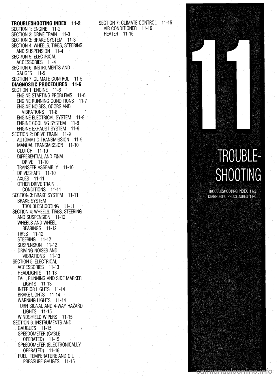
TROUBLESHOOTING INDEX 11-2
SECTION 1: ENGINE 11-2
SECTION 2: DRIVE TRAIN
11-3
SECTION 3:BRAKESYSTEM 11-3
SECTION 4:WHEELS,TIRES, STEERING,
AND SUSPENSION II-4
SECTION 5: ELECTRICAL
ACCESSORIES II-4
SECTION 6:lNSTRUMENTSAND
GAUGES II-5
SECTION 7:CLlMATE CONTROL II-5
DIAGNOSTIC PROCEDURES II-6
SECTION 1: ENGINE II-6
ENGINE STARTING PROBLEMS II-6
ENGINE RUNNING CONDITIONS II-7
ENGINE NOISES,ODORSAND
VIBRATIONS II-8
ENGINE ELECTRICALSYSTEM 11-8
ENGINE COOLING SYSTEM II-8
ENGINE EXHAUSTSYSTEM II-9
SECTION 2: DRIVE TRAIN
II-9
AUTOMATIC TRANSMISSION II-9
MANUALTRANSMISSION II-10
CLUTCH II-10
DIFFERENTIAL AND FINAL
DRIVE II-10
TRANSFER ASSEMBLY II-10
DRIVESHAFT II-10
AXLES II-II
OTHER DRIVE TRAIN
CONDITIONS II-II
SECTION 3:BRAKE SYSTEM II-II
BRAKESYSTEM
TROUBLESHOOTING II-II
SECTION 4:WHEELS, TIRES, STEERING
AND SUSPENSION II-12
WHEELSAND WHEEL
BEARINGS II-12
TIRES II-12
STEERING II-12
SUSPENSION II-12
DRIVING NOISES AND
VIBRATIONS II-13
SECTION 5:ELECTRlCAL
ACCESSORIES II-13 -
HEADLIGHTS II-13
TAIL, RUNNING AND SIDE MARKER
LIGHTS II-13
INTERIOR LIGHTS II-14
BRAKE LIGHTS II-14
WARNING LIGHTS II-14
TURN SlGNALAND4-WAYHAZARD
LIGHTS II-15
WINDSHIELD WIPERS II-15
SECTION 6:lNSTRUMENTSAND
GAUGUES II-15
I
SPEEDOMETER(CABLE
OPERATED) II-15
SPEEDOMETER(ELECTRONICALLY
OPERATED) II-16
FUEL,TEMPERATUREAkJD OIL
PRESSURE GAUGES II-16 SECTION 7:CLlMATECON
AIR CONDITIONER ll-
HEATER II-16 TR(
-16 IL II-16
Page 385 of 408
I TROUBLESHOOTING II-3
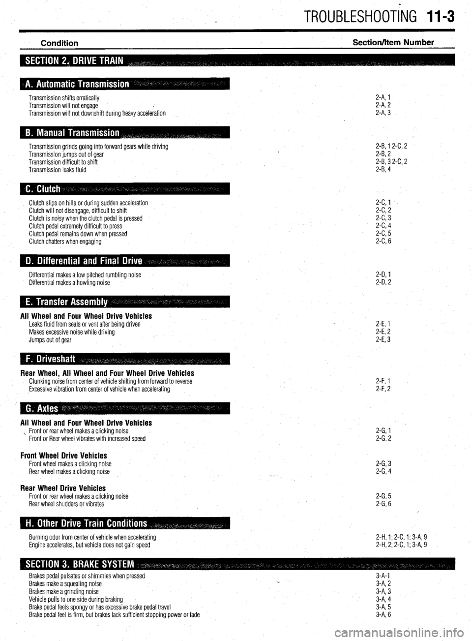
Condition Section/hem Number
2-A, 1
2-A, 2
2-A, 3 Transmission shifts erratically
Transmission will not engage
Transmission will not downshift during heavy acceleration
Transmission grinds going into forward gears while driving
Transmission jumps out of gear
Transmission difficult to shift
Transmission leaks fluid 2-B, 1 2-C, 2
2-B, 2
2-B, 3 2-C, 2
2-B, 4
2-C,l
2-c,2
2-c,3
2-c,4
2-c,5
2-C,6 Clutch slips on hills or during sudden acceleration
Clutch will not disengage, difficult to shift
Clutch is noisy when the clutch pedal is pressed
Clutch pedal extremely difficult to press
Clutch pedal remains down when pressed
Clutch chatters when engaging
2-D, 1
2-D, 2 Differential makes a low pitched rumbling noise
Differential makes a howling noise
All Wheel and Four Wheel Drive Vehicles Leaks fluid from seals or vent after being driven
Makes excessive noise while driving
Jumps out of gear 2-E, 1
2-E, 2
2-E, 3
Rear Wheel, All Wheel and Four Wheel Drive Vehicles Clunking noise from center of vehicle shifting from forward to reverse
,Excessive vibration from center of vehicle when accelerating 2-F, l
2-F,2
All Wheel and Four Wheel Drive Vehicles , Front or rear wheel makes a clicking noise
Front or Rear wheel vibrates with increased speed 2-G,l
2-G,2
Front Wheel Drive Vehicles Front wheel makes a clicking noise
Rear wheel makes a clicking noise 2-G,3
2-G,4
Rear Wheel Drive Vehicles Front or rear wheel makes a clicking
Rear wheel shudders or vibrates noise 2-G,5
2-G,6
2-H, 1; 2-C, 1; 3-A, 9
2-H, 2; 2-C, 1; 3-A, 9 Burning odor from center of vehicle when accelerating
Engine accelerates, but vehicle does not gain speed
Brakes pedal pulsates or shimmies when pressed 3-A-l
Brakes make a squealing noise CI
3-A, 2
Brakes make a grinding noise
Vehicle pulls to one side during.braking
Brake pedal feels spongy or has excessive brake pedal travel
Brake pedal feel is firm, but brakes lack sufficient stopping power or fade 3-A, 3
3-A, 4
3-A, 5
3-A, 6
Page 392 of 408
II-10 TROUBLESHOOTING
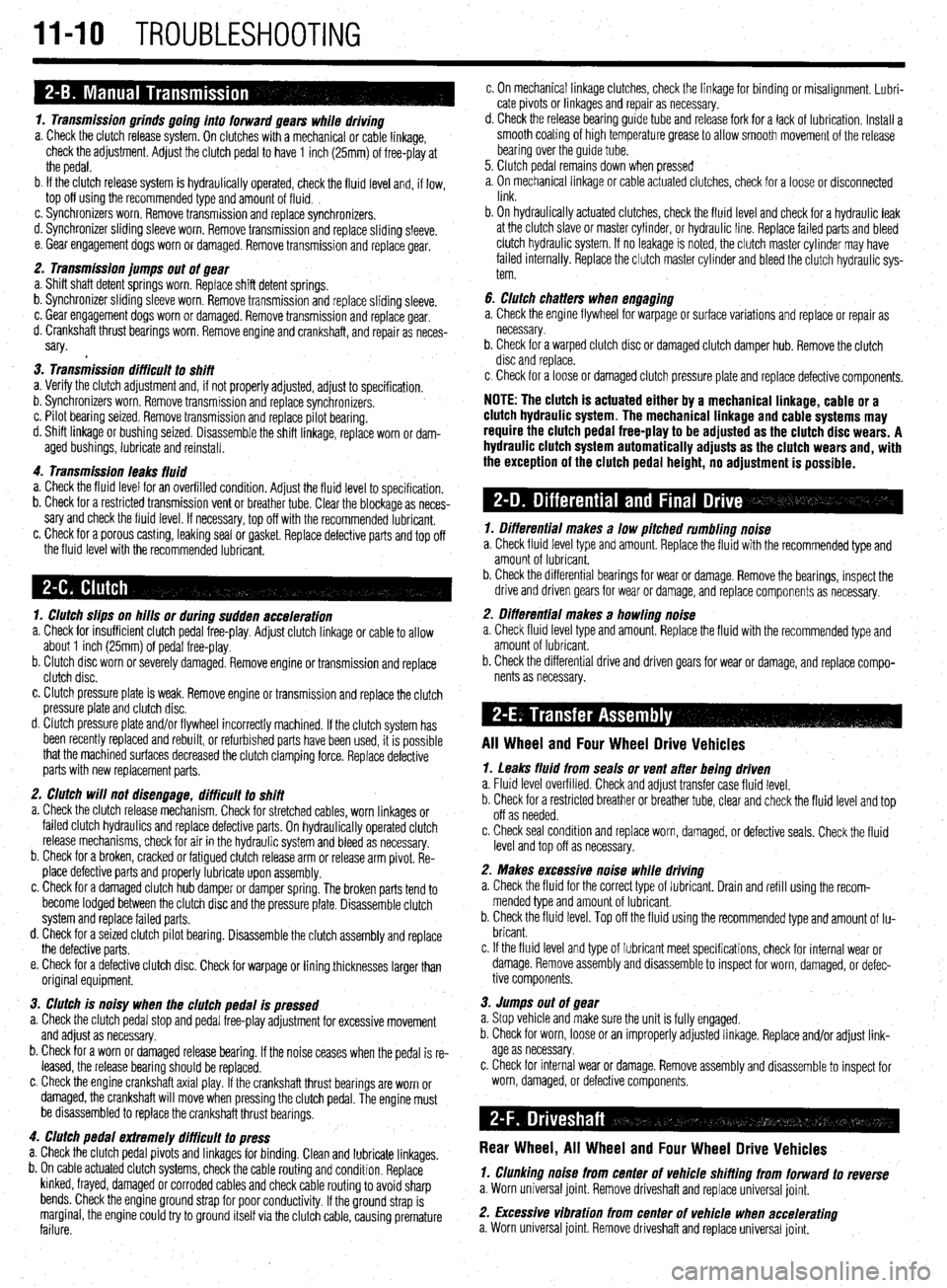
1. Transmission grinds going into forward gears while driving
a. Check the clutch release system. On clutches with a mechanical or cable linkage,
check the adjustment. Adjust the clutch pedal to have 1 inch (25mm) of free-play at
the pedal.
b. If the clutch release system is hydraulically operated, check the fluid level and, if low,
top off using the recommended type and amount of fluid. ,
c. Synchronizers worn. Remove transmission and replace synchronizers.
d. Synchronizer sliding sleeve worn. Remove transmission and replace sliding sleeve.
e. Gear engagement dogs worn or damaged. Remove transmission and replace gear.
2. Transmission jumps out of gear
a. Shift shaft detent springs worn. Replace shift detent springs.
b. Synchronizer sliding sleeve worn. Remove transmission and replace sliding sleeve.
c. Gear engagement dogs worn or damaged. Remove transmission and replace gear.
d. Crankshaft thrust bearings worn. Remove engine and crankshaft, and repair as neces-
sary.
3. Transmission difficult to shift
a. Verify the clutch adjustment and, if not properly adjusted, adjust to specification.
b. Synchronizers worn. Remove transmission and replace synchronizers.
c. Pilot bearing seized. Remove transmission and replace pilot bearing.
d. Shift linkage or bushing seized. Disassemble the shift linkage, replace worn or dam-
aged bushings, lubricate and reinstall.
4. Transmission leaks fluid
a. Check the fluid level for an overfilled condition. Adjust the fluid level to specification.
b. Check for a restricted transmission vent or breather tube. Clear the blockage as neces-
sary and check the fluid level. If necessary, top off with the recommended lubricant.
c. Check for a porous casting, leaking seal or gasket. Replace defective parts and top off
the fluid level with the recommended lubricant.
1. Clutch slips on hills or during sudden acceleration
a. Check for insufficient clutch pedal free-play. Adjust clutch linkage or cable to allow
about 1 inch (25mm) of pedal free-play.
b. Clutch disc worn or severely damaged. Remove engine or transmission and replace
clutch disc.
c. Clutch pressure plate is weak. Remove engine or transmission and replace the clutch
pressure plate and clutch disc.
d. Clutch pressure plate and/or flywheel incorrectly machined. If the clutch system has
been recently replaced and rebuilt, or refurbished parts have been used, it is possible
that the machined surfaces decreased the clutch clamping force. Replace defective
parts with new replacement parts.
2. Clutch will not disengage, difficult to shift
a. Check the clutch release mechanism. Check for stretched cables, worn linkages or
failed clutch hydraulics and replace defective parts. On hydraulically operated clutch
release mechanisms, check for air in the hydraulic system and bleed as necessary.
b. Check for a broken, cracked or fatigued clutch release arm or release arm pivot. Re-
place defective parts and properly lubricate upon assembly.
c. Check for a damaged clutch hub damper or damper spring. The broken parts tend to
become lodged between the clutch disc and the pressure plate. Disassemble clutch
system and replace failed parts.
d. Check for a seized clutch pilot bearing. Disassemble the clutch assembly and replace
the defective parts.
e. Check for a defective clutch disc. Check for warpage or liningthicknesses larger than
original equipment.
3. Clutch is noisy when the clutch pedal is pressed
a. Check the clutch pedal stop and pedal free-play adjustment for excessive movement
and adjust as necessary.
b. Check for a worn or damaged release bearing. If the noise ceases when the pedal is re-
leased, the release bearing should be replaced.
c. Check the engine crankshaft axial play. If the crankshaft thrust bearings are worn or
damaged, the crankshaft will move when pressing the clutch pedal. The engine must
be disassembled to replace the crankshaft thrust bearings.
4. Clutch pedal extremely difficult to press
a. Check the clutch pedal pivots and linkages for binding. Clean and lubricate linkages.
b. On cable actuated clutch systems, check the cable routing and condition. Replace
kinked, frayed, damaged or corroded cables and check cable routing to avoid sharp
bends. Check the engine ground strap for poor conductivity. If the ground strap is
marginal, the engine could try to ground itself via the clutch cable, causing premature
failure. c. On mechanical linkage clutches, check the linkage for binding or misalignment. Lubri-
cate pivots or linkages and repair as necessary.
d. Check the release bearing guide tube and release fork for a lack of lubrication. Install a
smooth coating of high temperature grease to allow smooth movement of the release
bearing over the guide tube.
5. Clutch pedal remains down when pressed
a, On mechanical linkage or cable actuated clutches, check for a loose or disconnected
link.
b. On hydraulically actuated clutches, check the fluid level and check for a hydraulic leak
at the clutch slave or master cylinder, or hydraulic line. Replace failed parts and bleed
clutch hydraulic system. If no leakage is noted, the clutch master cylinder may have
failed internally. Replace the clutch master cylinder and bleed the clutch hydraulic sys-
tem.
6. clutch chatters when engaging
a. Check the engine flywheel for warpage or surface variations and replace or repair as
necessary.
b. Check for a warped clutch disc or damaged clutch damper hub. Remove the clutch
disc and replace.
c. Check for a loose or damaged clutch pressure plate and replace defective components.
NOTE: The clutch is actuated either by a mechanical linkage, cable or a
clutch hydraulic system. The mechanical linkage and cable systems may
require the clutch pedal free-play to be adjusted as the clutch disc wears. A
hydraulic clutch system automatically adjusts as the clutch wears and, with
the exception of the clutch pedal height, no adjustment is possible.
1. Differential makes a low pitched rumbling noise
a. Check fluid level type and amount. Replace the fluid with the recommended type and
amount of lubricant.
b. Check the differential bearings for wear or damage. Remove the bearings, inspect the
drive and driven gears for wear or damage, and replace components as necessary.
2. Differential makes a howling noise
a. Check fluid level type and amount. Replace the fluid with the recommended type and
amount of lubricant.
b. Check the differential drive and driven gears for wear or damage, and replace compo-
nents as necessary.
All Wheel and Four Wheel Drive Vehicles
1. Leaks fluid from seals or vent after being driven
a. Fluid level overfilled. Check and adjust transfer case fluid level.
b. Check for a restricted breather or breather tube, clear and check the fluid level and top
off as needed.
c. Check seal condition and replace worn, damaged, or defective seals. Check the fluid
level and top off as necessary.
2. Makes excessive noise while driving
a. Check the fluid for the correct type of lubricant. Drain and refill using the recom-
mended type and amount of lubricant.
b. Check the fluid level. Top off the fluid using the recommended type and amount of lu-
bricant.
c. If the fluid level and type of lubricant meet specifications, check for internal wear or
damage. Remove assembly and disassemble to inspect for worn, damaged, or defec-
tive components.
3. Jumps out of gear
a. Stop vehicle and make sure the unit is fully engaged.
b. Check for worn, loose or an improperly adjusted linkage. Replace and/or adjust link-
age as necessary.
c. Check for internal wear or damage. Remove assembly and disassemble to inspect for
worn, damaged, or defective components.
Rear Wheel, All Wheel and Four Wheel Drive Vehicles
1. Clunking noise from center of Vehicle shifting from forward to reverse
a. Worn universal joint. Remove driveshaft and replace universal joint.
2. Excessive vibration from center of vehicle when accelerating
a. Worn universal joint. Remove driveshaft and replace universal joint.
Page 400 of 408
11-18 GLOSSARY
COMBINATION MANIFOLD: An assembly which includes both the intake
and exhaust manifolds in one casting.
COMBINATION VALVE: A device used in some fuel systems that routes fuel
vapors to a charcoal storage canister instead of venting them into the atmos-
phere. The valve relieves fuel tank pressure
and allows fresh air into the tank
as the fuel level drops to prevent a vapor lock situation.
COMPRESSION RATIO: The ratio of the volume between the piston and
cylinder head when the piston is at the bottom of its stroke (bottom dead cen-
ter) and when the piston is at the top of its stroke (top dead center).
CONDENSER: 1. An electrical device which acts to store an electrical charge,
preventing voltage surges. 2. A radiator-like device in the air conditioning sys-
tem in which refrigerant gas condenses into a liquid, giving off heat.
CONDUCTOR: Any material through which an electrical current can be trans-
mitted easily.
CONTINUITY: Continuous or complete circuit. Can be checked with an ohm-
meter.
COUNTERSHAFT: An intermediate shaft which is rotated by a mainshaft and
transmits, in turn, that rotation to a working part.
CRANKCASE: The lower part of an engine in which the crankshaft and re-
lated parts operate.
CRANKSHAFT: Engine component (connected to pistons by connecting rods)
which converts the reciprocating (up and down) motion of pistons to rotary
motion used to turn the driveshaft.
CYLINDER: In an engine, the round hole in the engine block in which the
piston(s) ride.
CYLINDER BLOCK: The main structural member of an engine in which is
found the cylinders, crankshaft and other principle parts.
DEAD CENTER: The extreme top or bottom of the piston stroke.
DETONATION: An unwanted explosion of the air/fuel mixture in the com-
bustion chamber caused by excess heat and compression, advanced timing,
or an overly lean mixture. Also referred to as “ping”.
DIAPHRAGM: A thin, flexible wall separating two cavities, such as in a vac-
uum advance unit.
c
DIESELING: The engine continues to run after the car is shut off; caused by
fuel continuing to be burned in the combustion chamber.
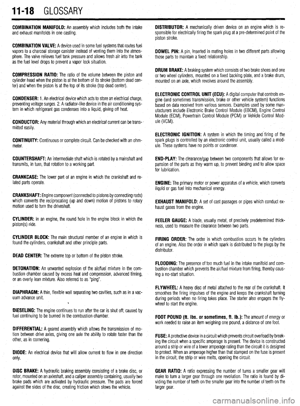
DIFFERENTIAL: A geared assembly which allows the transmission of mo-
tion between drive axles, giving one axle the ability to rotate faster than the
other, as in cornering.
DIODE: An electrical device that will allow current to flow in one direction
only.
DISC BRAKE: A hydraulic braking assembly consisting of a brake disc, or
rotor, mounted on an axleshaft, anda caliper assembly containing, usually two GEAR RATIO: A ratio expressing the number of turns a smaller gear will
make to turn a larger gear through one revolution. The ratio is found by di-
brake pads which are activated by hydraulic pressure. The pads are forced viding the number of teeth on the smaller gear into the number of teeth on the
against the sides of the disc, creating friction which slows the vehicle. larger gear. DISTRIBUTOR: A mechanically driven device on an engine which is re-
sponsible for electrically firing the spark plug at a pre-determined point of the
piston stroke.
DOWEL PIN: A pin, inserted in mating holes in two different parts allowing
those parts to maintain a fixed relationship. .
DRUM BRAKE: A braking system which consists of two brake shoes and one
or two wheel cylinders, mounted on a fixed backing plate, and a brake drum,
mounted on an axle, which revolves around the assembly.
ELECTRONIC CONTROL UNIT (ECU): A diqital computer that controls en-
gine (and sometimes transmission‘, brake or other vehicle system) functions
based on data received from various sensors. Examples used by some man-
ufacturers include Electronic Brake Control Module (EBCM), Engine Control
Module (ECM), Powertrain Control Module (PCM) or Vehicle Control Mod-
ule (VCM).
ELECTRONIC IGNITION: A system in which the timing and‘firing of the
spark plugs is controlled by an electronic control unit, usually called a mod-
ule. These systems have no points or condenser,
END-PLAY: The clearance/gap between two components that allows for ex-
pansion of the parts as they warm up, to prevent binding and to allow space
for lubrication.
ENGINE: The primary motor or power apparatus of a vehicle, which converts
liquid or gas fuel into mechanical energy.
EXHAUST MANIFOLD: A set of cast passages or pipes which conduct ex-
haust gases from the engine.
FEELER GAUGE: A blade, usually metal, of precisely predetermined thick-
ness, used to measure the clearance between two parts.
FIRING ORDER: The order in which combustion occurs in the cylinders
of an engine. Also the order in which spark is distributed to the plugs by the
distributor.
FLOODING: The presence of too much fuel in the intake manifold and com-
bustion chamber which prevents the air/fuel mixture from firing, thereby caus-
ing a no-start situation.
FLYWHEEL: A heavy disc of metal attached to the rear of the crankshaft. It
smoothes the firing impulses of the engine and keeps the crankshaft turning
during periods when no firing takes place. The starter also engages the fly-
wheel to start the engine.
FOOT POUND (ft. Ibs. or sometimes, ft. lb.): The amount of energy or
work needed to raise an item weighing one pound, a distance of one foot.
FUSE: A protective device in a circuit which prevents circuit overload by break-
ing the circuit when a specific amperage is present. The device is constructed
around a strip or wire of a lower amperage rating than the circuit it is designed
to protect. When an amperage higher than that stamped on the fuse is present
in the circuit, the strip or wire melts, opening the circuit.
Page 401 of 408
GLOSSARY 1149
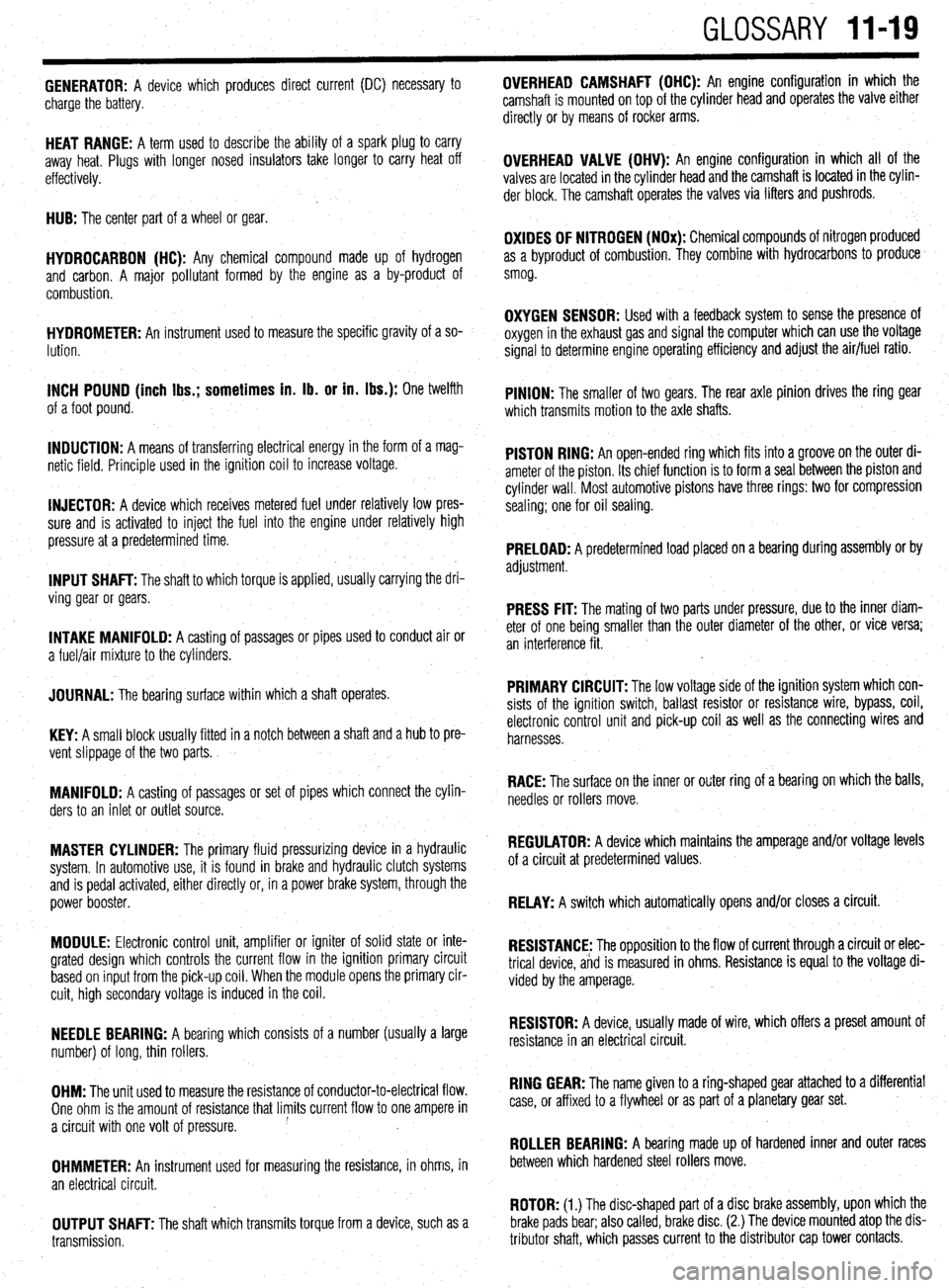
GENERATOR: A device which produces direct current (DC) necessary to
charge the battery. OVERHEAD CAMSHAFT (OHC): An engine configuration in which the
camshaft is mounted on top of the cylinder head and operates the valve either
directly or by means of rocker arms.
HEAT RANGE: A term used to describe the ability of a spark plug to carry
away heat. Plugs with longer nosed insulators take longer to carry heat off
effectively.
HUB: The center part of a wheel or gear.
HYDROCARBON (HC): Any chemical compound made up of hydrogen
and carbon. A major pollutant formed by the engine as a by-product of
combustion.
HYDROMETER: An instrument used to measure the specific gravity of a so-
lution.
INCH POUND (inch Ibs.; sometimes in. lb. or in. Ibs.): One twelfth
.
of a foot pound.
INDUCTION: A means of transferring electrical energy in the form of a mag-
netic field. Principle used in the ignition coil to increase voltage.
INJECTOR: A device which receives metered fuel under relatively low pres-
sure and is activated to inject the fuel into the engine under relatively high
pressure at a predetermined time.
INPUT SHAFT: The shaft to which torque is applied, usually carrying the dri-
ving gear or gears.
INTAKE MANIFOLD: A casting of passages or pipes used to conduct air or
a fuel/air mixture to the cylinders.
JOURNAL: The bearing surface within which a shaft operates.
KEY: A small block usually fitted in a notch between a shaft and a hub to pre-
vent slippage of the two parts.
MANIFOLD: A casting of passages or set of pipes which connect the cylin-
ders to an inlet or outlet source.
MASTER CYLINDER: The primary fluid pressurizing device in a hydraulic
system. In automotive use, it is found in brake and hydraulic clutch systems
and is pedal activated, either directly or, in a power brake system, through the
power booster.
MODULE: Electronic control unit, amplifier or igniter of solid state or inte-
grated design which controls the current flow in the ignition primary circuit
based on input from the pick-up coil. When the module opens the primary cir-
cuit, high secondary voltage is induced in the coil.
NEEDLE BEARING: A bearing which consists of a number (usually a large
number) of long, thin rollers.
OHM: The unit used to measure the resistance of conductor-to-electrical flow.
One ohm is the amount of resistance that limits current flow to one ampere in
a circuit with one volt of pressure.
OHMMETER: An instrument used for measuring the resistance, in ohms, in
an electrical circuit.
OUTPUT SHAFT: The shaft which transmits torque from a device, such as a
transmission. OVERHEAD VALVE (OHV): An engine configuration in which all of the
valves are located in the cylinder head
and the camshaft is located in the cylin-
der block. The camshaft operates the valves via lifters and pushrods.
OXIDES OF NITROGEN (NOx): Chemical compounds of nitrogen produced
as a byproduct of combustion. They combine with hydrocarbons to produce
smog.
OXYGEN SENSOR: Used with a feedback system to sense the presence of
oxygen in the exhaust gas and signal the computer which can use the voltage
signal to determine engine operating efficiency and adjust the air/fuel ratio.
PINION: The smaller of two gears. The rear axle pinion drives the ring gear
which transmits motion to the axle shafts.
PISTON RING: An open-ended ring which fits into a groove on the outer di-
ameter of the piston. Its chief function is to form a seal between the piston and
cylinder wall. Most automotive pistons have three rings: two for compression
sealing; one for oil sealing.
PRELOAD: A predetermined load placed on a bearing during assembly or by
adjustment.
PRESS FIT: The mating of two parts under pressure, due to the inner diam-
eter of one being smaller than the outer diameter of the other, or vice versa;
an interference fit.
PRIMARY CIRCUIT: The low voltage side of the ignition system which con-
sists of the ignition switch, ballast resistor or resistance wire, bypass, coil,
electronic control unit and pick-up coil as well as the connecting wires and
harnesses.
RACE: The surface on the inner or otiter ring of a bearing on which the balls,
needles or rollers move.
REGULATOR: A device which maintains the amperage and/or voltage levels
of a circuit at predetermined values.
RELAY: A switch which automatically opens and/or closes a circuit.
RESISTANCE: The opposition to the flow of current through a circuit or elec-
trical device, and is measured in ohms. Resistance is equal to the voltage di-
vided by the amperage.
RESISTOR: A device, usually made of wire, which offers a preset amount of
resistance in an electrical circuit.
RING GEAR: The name given to a ring-shaped gear attached to a differential
case, or affixed to a flywheel or as part of a planetary gear set.
ROLLER BEARING: A bearing made up of hardened inner and outer races
between which hardened steel rollers move.
ROTOR: (1.) The disc-shaped part of a disc brake assembly, upon which the
brake pads bear; also called, brake disc. (2.) The device mounted atop the dis-
tributor shaft, which passes current to the distributor cap tower contacts.
Page 406 of 408
l
II-24 MASTER INDEX
ADJUSTMENT 8-25
REMOVAL &INSTALLATION 8-25
HYDRAULIC CONTROL UNIT 9-25
REMOVAL & INSTALLATION 9-25
IDLE AIR CONTROLMOTOR 4-9
OPERATION 4-9
REMOVAL&INSTALLATION 4-9
TESTING 4-9
IDLESPEED 1-28
PREVENTIVEMAINTENANCE 1-28
SYSTEM INSPECTION 1-29
SYSTEMSERVlCE&REPAlR 1-28
IGNITION LOCK CYLINDER 8-29
REMOVAL & INSTALLATION 8-29
IGNITION SWITCH 8-30
REMOVAL & INSTALLATION 8-30
IGNITION COIL(s) 2-5
REMOVAL&INSTALLATION 2-6
TESTING . 2-5
IGNITION COIL 2-3
REMOVAL&INSTALLATION 2-3
TESTING 2-3
IGNITION TIMING l-25
GENERALINFORAMTION l-25
INSPECTION&ADJUSTMENT l-26
INSIDE REAR VIEW MIRROR
IO-IO
REPLACEMENT IO-IO
INSPECTION 3-55
REPLACEMENT 3-56
INSTRUMENT CLUSTER 6-17
REMOVAL&INSTALLATION 6-I;
INSTRUMENTPANEL IO-6
REMOVAL &INSTALLATION IO-6
INSTRUMENTS AND SWITCHES 6-17
INTAKE MANIFOLD 3-7
REMOVAL &INSTALLATION 3-7
INTAKEAIRTEMPERATURESENSOR 4-10
OPERATION 4-10
REMOVAL&INSTALLATION 4-11
TESTING 4-11
INTERIOR 1 O-6
JACKING I-46
. JACKING PRECAUTIONS 1-47
JUMP STARTING A DEAD BATTERY 1-44
JUMPSTARTING PRECAUTIONS l-45
JUMPSTARTING PROCEDURE l-45
KNUCKLE,HUB, AND BEARING 8-13
REMOVAL &INSTALLATION 8-13
LIGHTING 6-19
LOWER BALLJOINT 8-10
INSPECTION 8-10
REMOVAL & INSTALLATION 8-10
LOWER CONTROLARM 8-10
REMOVAL&INSTALLATION 8-10
LOWER CONTROL ARMS 8-23
REMOVAL & INSTALLATION 8-23
MACPHERSONSTRUTAND COILSPRING
8-7
OVERHAUL 8-7
REMOVAL & INSTALLATION 8-7
MAINTENANCEORREPAIR? l-2
MANIFOLDABSOLUTEPRESSURESENSOR
4-12
OPERATION 4-12
REMOVAL&INSTALLATION 4-13
TESTING 4-12
MANUAL RACK AND PINION STEERING GEAR
8-31
REMOVAL & INSTALLATION 8-31
MANUALTRANSAXLEASSEMBLY 7-2
REMOVAL & INSTALLATION. 7-2
MANUAL TRANSAXLE 7-2 MANUALTRANSAXLE l-35
DRAIN &REFILL l-36
FLUID RECOMMENDATIONS l-35
LEVEL CHECK l-35
MASSAIRFLOWSENSOR 4-11
OPERATION 4-11
REMOVAL&INSTALLATION 4-11
TESTING 4-11
MASTER CYLINDER 9-3
BRAKE PEDALADJUSTMENTS 9-4
REMOVAL & INSTALLATION 9-3
MULTI-POINT FUEL INJECTION SYSTEM (MPI) 5-3
DBD-1 TROUBLE CODES 4-26
OBD-II TROUBLE CODES 4-27
OIL PAN 3-30
REMOVAL & INSTALLATION 3-30
OIL PUMP 3-33
REMOVAL & INSTALLATION 3-33
OIL PRESSURESENDING UNIT 2-12@T
REMOVAL&INSTALLATION 2-1.2
TESTING 2-12
OUTSIDE MIRRORS IO-3
REMOVAL&INSTALLATION IO-3
OXYGENSENSOR 4-8
OPERATION 4-8
REMOVAL&INSTALLATION 4-8
TESTING 4-8
PARK/NEUTRAL POSITIONSWITCH 7-10
ADJUSTMENT 7-10
REMOVAL & INSTALLATION 7-10
PARKING BRAKE 9-20
PCVVALVE l-15
REMOVAL&INSTALLATION I-15
PINION SEAL 7-16
REMOVAL &INSTALLATION 7-16
POWER BRAKEBOOSTER 9-5
REMOVAL &INSTALLATION 9-5
POWER RACK AND PINION STEERING GEAR 8-32
REMOVAL &INSTALLATION 8-32
POWERSEATMOTOR IO-11
REMOVAL & INSTALLATION IO-11
POWER STEERING PUMP 8-34
REMOVAL & INSTALLATION 8-34
SYSTEM BLEEDING 8-36
POWER TRANSlSTOR(IGNITION MODULE) 2-7
REMOVAL&INSTALLATION 2-7
POWERSTEERING PUMP l-42
FLUID RECOMMENDATIONS l-42
LEVELCHECK l-42
POWER TRANSlSTOR(Ignition Module) 2-4
REMOVAL&INSTALLATION 2-4
PRESSURERELIEFVALVE 5-9
REMOVAL&INSTALLATION 5-9
PROPORTIONING VALVE 9-6
REMOVAL & INSTALLATION 9-6 *
RADIATOR 3-18
REMOVAL &INSTALLATION 3-18
RADIO RECEIVER/AMPLIFIER/TAPE PLAYER/CD PLAYER 6-14
READING CODES 4-26
WITHASCANTOOL 4-26
WITHOUTASCANTOOL 4-27
READING CODES 4-27
WITHASCANTOOL 4-27
WITHOUTASCANTOOL 4-27
REAR AXLE DIFFERENTIAL 7-15
REAR HALFSHAFTAND SEAL 7-15
REMOVAL&INSTALLATION 7-15
REAR MAIN SEAL 3-54
REMOVAL & INSTALLATION 3-54