1900 MITSUBISHI DIAMANTE diagram
[x] Cancel search: diagramPage 278 of 408
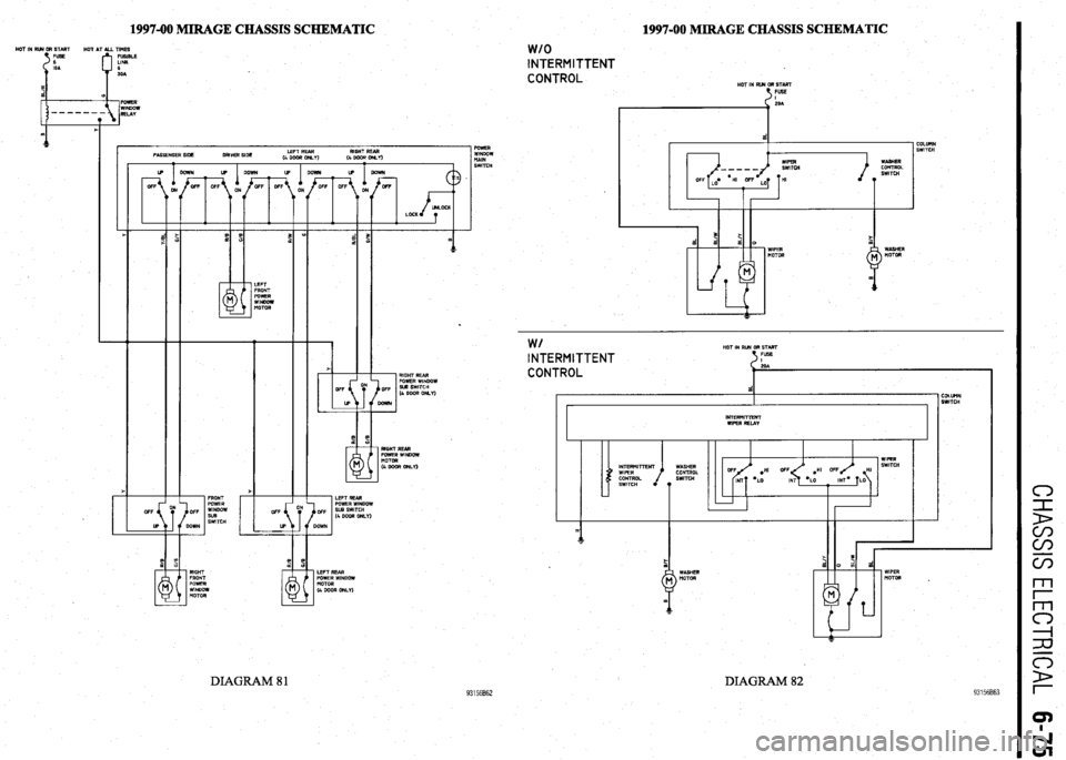
1997-00 MIRAGE CHASSIS SCHEMATIC HOT IN RR4 OR STMT
HOT AT ALL TIMES
FUSIBLE
LINK
6
SOA 1997-00 MIRAGE CHASSIS SCHEMATIC
1 POWER
WINDOW
tiAlN
SWITCH
w/o INTERMITTENT
CONTROL
HOT IN RUN OR START
t FUSE
COLUllN
SWITCH
LEFT REAR RIGHT REAR
4 DOOR or&Y)
(4WWOM.I)
I .
F ?E
d d a 0
WIPER WASHER
MOTOR MOTOR
.
93156862
W/ HOT IN RUN GR START INTERMITTENT FUSE 5
CONTROL
d COLUtlN
SWITCH
I r INTERMITTENT
WIPER RELAY
I I
WIPER
WASHER SWITCH
CONTROL .HI OFF HI
SWITCH
*LO MT= LO
T
1
LEFT REAR
POWER WINDOW
MOTOR
(4 GOOR ONLY) RIGHT
FRONT
POWER
WINDOW
MOTOR WIPER
MOTOR .
DIAGRAM 82 DIAGRAM 81
Page 279 of 408
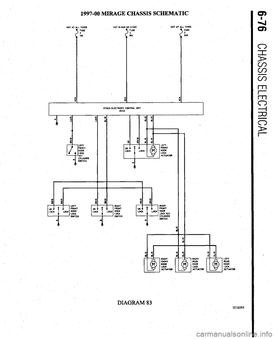
1997-00 MIRAGE CHASSIS SCHEMATIC
START HOT AT
FUSE
I
IOA
ETACS ELECTRONIC CCMROL
(ECU1 _ TIMES
FUSE
J
LOA
DIAGRAM 83 93156B64
Page 395 of 408
TROUBLESHOOTING 11-13
NOTE: When one shock fails, ft is recommended to replace front or rear
units as pairs.
3. Vehicle leans excessively in turns
a. Check for worn or leaking shock absorbers or strut assemblies and replace as neces-
sary.
b. Check for missing, damaged, or worn stabilizer links or bushings, and replace or in-
stall as necessary.
4. Vehicle ride quality seems excessively ha&h
a. Check for seized shock absorbers or strut assemblies and replace as necessary.
b. Check for excessively high tire pressures and adjust pressures to vehicle recommen-
dations.
5. Vehicle seems low or leans to one side
a. Check for a damaged, broken or weak spring. Replace defective parts and check for a
needed alignment.
b. Check for seized shock absorbers or strut assemblies and replace as necessary.
c. Check for worn or leaking shock absorbers or strut assemblies and replace as neces-
sary.
Noises 1. Vehicle makes a clicking noises when driven
a. Check the noise to see if it varies with road speed. Verify if the noise is present when
coasting or with steering or throttle input. If the clicking noise frequency changes with
road speed and is not affected by steering or throttle input, check the tire treads for a
stone, piece of glass, nail or another hard object imbedded into the tire or tire tread.
Stones rarely cause a tire puncture and are easily removed. Other objects may create
an air leak when removed. Consider having these objects removed immediately at a
facility equipped to repair tire punctures.
b. If the clicking noise varies with throttle input and steering, check for a worn Constant
Velocity (CV-joint) joint, universal (U- joint) or flex joint.
2. Vehicle makes a clunking or knocking noise over bumps
a. A clunking noise over bumps is most often caused by excessive movement or clear-
ance in a suspension component. Check the suspension for soft, cracked, damaged or
worn bushings. Replace the bushings and check the vehicle’s alignment.
b. Check for loose suspension mounting bolts. Check the tightness on subframe bolts,
pivot bolts and suspension mounting bolts, and torque to specification.
c. Check the vehicle for a loose wheel bearing. Some wheel bearings can be adjusted for
looseness, while others must be replaced if loose. Adjust or replace the bearings as
recommended by the manufacturer.
d. Check the door latch adjustment. If the door is slightly loose, or the latch adjustment
is not centered, the door assembly may create noises over bumps and rough surfaces.
Properly adjust the door latches to secure the door. 3. Vehicle makes a low pitched rumbling noise when driven
a. A low pitched rumbling noise is usually caused by a drive train related bearing and is
most often associated with a wheel bearing which has been damaged or worn. The
damage can be caused by excessive brake temperatures or physical contact with a pot
hole or curb. Sometimes the noise will vary when turning. Left hand turns increase the
load on the vehicle’s right side, and right turns load the left side. A failed front wheel
bearing may also cause a slight steering wheel vibration when turning. A bearing
which exhibits noise must be replaced.
b. Check the tire condition and balance. An internally damaged tire may cause failure
symptoms similar to failed suspension parts. For diagnostic purposes, try a known
good set of tires and replace defective tires.
4. Vehicle makes a squeaking noise over bumps
a. Check the vehicle’s ball joints for wear, damaged or leaking boots. Replace a ball joint
if it is loose, the boot is damaged and leaking, or the ball joint is binding. When re-
placing suspension parts, check the vehicle for alignment.
b. Check for seized or deteriorated bushings. Replace bushings that are worn or dam-
aged and check the vehicle for alignment.
c. Check for the presence of sway bar or stabilizer bar bushings which wrap around the
bar. Inspect the condition of the bushings and replace if worn or damaged. Remove
the bushing bracket and apply a thin layer of suspension grease to the area where the
bushings wrap around the bar and reinstall the bushing brackets. ~
5. Vehicle vibrates when driven
a. Check the road surface. Roads which have rough or uneven surfaces may cause un-
usual vi brations.
b. Check the tire condition and balance. An internally damaged tire may cause failure
symptoms similar to failed suspension parts. For diagnostic purposes, try a known
good set of tires and replace defective tires immediately.
c. Check for a worn Constant Velocity (CV-joint) joint, universal (U- joint) or flex joint
and replace if loose, damaged or binding.
d. Check for a loose, bent, or out-of-balance axle or drive shaft. Replace damaged or
failed components.
NOTE: Diagnosing failures related to wheels, tires, steering and the sus-
pension system can often times be accomplished with a careful and thor-
ough test drive. Bearing noises are isolated by noting whether the noises
or symptoms vary when turning left or right, or occur while driving a
straight line. During a teft hand turn, the vehicle’s weight shifts to the
right, placing more force on the right side bearings, such that if a right side
wheel bearing is worn or damaged, the noise or vibration should increase
during light-to-heavy acceleration. Conversely, on right hand turns, the ve-
hicle tends to lean to the left, loading the left side bearings.
Knocking noises in the suspension when the vehicle is driven over rough roads, rail-
road tracks and speed bumps indicate worn suspension components such as bushings,
ball joints or tie rod ends, or a worn steering system.
1. One headlight only works on high or low beam
a. Check for battery voltage at headlight electrical connector. If battery voltage is present,
replace the headlight assembly or bulb if available separately. If battery voltage is not
present, refer to the headlight wiring diagram to troubleshoot.
2. Headlight does not work on high or low beam
a. Check for battery voltage and ground at headlight electrical connector. If battery volt-
age is present, check the headlight connector ground terminal for a proper ground. If
battery voltage and ground are present at the headlight connector, replace the head-
light assembly or bulb if available separately. If battery voltage or ground is not pre-
sent, refer to the headlight wiring diagram to troubleshoot.
b. Check the headlight switch operation. Replace the switch if the switch is defective or
ooerates intermittentlv. 1. Tail light, running light or side marker light inoperative
a. Check for battery voltage and ground at light’s electrical connector. If battery voltage is
present, check the bulb socket and electrical connector ground terminal for a proper
ground. If battery voltage and ground are present at the light connector, but not in the
socket, clean the socket and the ground terminal connector. If battery voltage and
ground are present in the bulb socket, replace the bulb. If battery voltage or ground is
not present, refer to the wiring diagram to troubleshoot for an open circuit.
b. Check the light switch operation and replace if necessary.
2. Tall light, running light or side marker light works intermittently
a. Check the bulb for a damaged filament, and replace if damaged.
b. Check the bulb and bulb socket for corrosion, and clean or replace the bulb and
socket.
w 3. Headlight(s) very dim
a. Check for battery voltage and ground at headlight electrical connector. If battery volt-
age is present, trace the ground circuit for the headlamp electrical connector, then
clean and repair as necessary. If the voltage at the headlight electrical connector is
significantly less than the voltage at the battery, refer to the headlight wiring diagram
to troubleshoot and locate the voltage drop. c. Check for loose, damaged or corroded wires and electrical terminals, and repair as
necessary.
d. Check the light switch operation and replace if necessary.
3. Tail light, running light or side marker light very dim
a. Check the bulb and bulb socket for corrosion and clean or replace the bulb and
socket.
Page 396 of 408
II-14 TROUBLESHOOTING
b. Check for low voltage at the bulb socket positive terminal or a poor ground. If voltage
is low, or the ground marginal, trace the wiring to, and check for loose, damaged or
corroded wires and electrical terminals; repair as necessary.
c. Check the light switch operation and replace if necessary.
1. Interior light inoperative
a. Verify the interior light switch location and position(s), and set the switch in the cor-
rect position.
b. Check for battery voltage and ground at the interior light bulb socket. If battery voltage
and ground are present, replace the bulb. If voltage is not present, check the interior
light fuse for battery voltage. If the fuse is missing, replace the fuse. If the fuse has
blown, or if battery voltage is present, refer to the wiring diagram to troubleshoot the
cause for an open or shorted circuit. If ground is not present, check the door switch
contacts and clean or repair as necessary.
2. Interior light works intermittent/y
a. Check the bulb for a damaged filament, and replace if damaged.
b. Check the bulb and bulb socket for corrosion, and clean or replace the bulb and
socket.
c. Check for loose, damaged or corroded wires and electrical terminals; repair as neces-
sary.
d. Check the door and light switch operation, and replace if necessary.
3. Interior light very dim
a. Check the bulb and bulb socket for corrosion, and clean or replace the bulb and
socket.
b. Check for low voltage at the bulb socket positive terminal or a poor ground. If voltage
is low, or the ground marginal, trace the wiring to, and check for loose, damaged or
corroded wires and electrical terminals; repair as necessary.
c. Check the door and light switch operation, and replace if necessary.
1. One brake light inoperative
a. PressPress the brake pedal and check for battery voltage and ground at the brake light
bulb socket. If present, replace the bulb. If either battery voltage or ground is not pre-
sent, refer to the wiring diagram to troubleshoot.
2. Both brake lights inoperative
a. Press the brake pedal and check for battery voltage and grou’nd at the brake light bulb
socket. If present, replace both bulbs. If battery voltage is not present, check the brake
light switch adjustment and adjust as necessary. If the brake light switch is properly
adjusted, and battery voltage or the ground is not present at the bulb sockets, or at the
bulb electrical connector with the brake pedal pressed, refer to the wiring diagram to
troubleshoot the cause of an open circuit.
3. One or both brake lights very dim
a. Press the brake pedal and measure the voltage at the brake light bulb socket. If the
measured voltage is close to the battery voltage, check for a poor ground caused by a
loose, damaged, or corroded wire, terminal, bulb or bulb socket. If the ground is
bolted to a painted surface, it may be necessary to remove the electrical connector and
clean the mounting surface, so the connector mounts on bare metal. If battery voltage
is low, check for a poor connection caused by either a faulty brake light switch, a
loose, damaged, or corroded wire, terminal or electrical connector. Refer to the wiring
diagram to troubleshoot the cause of a voltage drop.
1. Warning light(s) stay on when the engine is started
Ignition, Battery or Alternator Warning light a. Check the alternator output and voltage regulator operation, and replace as necessary.
b. Check the warning light wiring for a shorted wire.
Check Engine Light a. Check the engine for routine maintenance and tune-up status. Note the engine tune-up
specifications and verify the spark plug, air filter and engine oil condition; replace
and/or adjust items as necessary.
b. Check the fuel tank for low fuel level, causing an intermittent lean fuel mixtur
e. Top off fuel tank and reset check engine light.
c. Check for a failed or disconnected engine fuel or ignition component, sensor or con-
trol unit and repair or replace as necessary.
d. Check the intake manifold and vacuum hoses for air leaks and repair as
necessary.
e. Check the engine’s mechanical condition for excessive oil consumption.
Anti-Lock Braking System (ABS) Light a. Check the wheel sensors and sensor rings for debris, and clean as necessary.
b. Check the brake master cylinder for fluid leakage or seal failure and replace as neces-
sary.
c, Check the ABS control unit, pump and proportioning valves for proper operation; re-
place as necessary.
d. Check the sensor wiring at the wheel sensors and the ABS control unit for a loose or
shorted wire, and repair as necessary.
brake Warning Light a. Check the brake fluid level and check for possible leakage from the hydraulic lines and
seals. Top off brake fluid and repair leakage as necessary.
b. Check the brake linings for wear and replace as necessary.
c. Check for a loose or shot-ted brake warning light sensor or wire, and replace or repair
as necessary.
Oil Pressure Warning Light a. Stop the engine immediately. Check the engine oil level and oil filter condition, and
top off or change the oil as necessary.
b. Check the oil pressure sensor wire for being shorted to ground. Disconnect the wire
from the oil pressure sensor and with the ignition in the ON position, but not running,
the oil pressure light should not be working. If the light works with the wire discon-
nected, check the sensor wire for being shorted to ground. Check the wire routing to
make sure the wire is not pinched and check for insulation damage. Repair or replace
the wire as necessary and recheck before starting the engine.
c. Remove the oil pan and check for a clogged oil pick-up tube screen.
d. Check the oil pressure sensor operation by substituting a known good sensor.
e. Check the oil filter for internal restrictions or leaks, and replace as necessary.
WARNING: If the engine is operated with oil pressure below the manufac-
turer’s specification, severe (and costly) engine damage could occur. Low
oil pressure can be caused by excessive internal wear or damage to the en-
gine bearings, oil pressure relief valve, oil pump or oil pump drive mecha-
nism.
Before starting the engine, check for possible causes of rapid oil loss, such as leaking
oil lines or a loose, damaged, restricted, or leaking oil filter or oil pressure sensor. If the
engine oil level and condition are acceptable, measure the engine’s oil pressure using a
pressure gauge, or determine the cause for the oil pressure warning light to function
when the engine is running, before operating the engine for an extended period of time.
Another symptom of operating an engine with low oil pressure is the presence of severe
knocking and tapping noises.
Parking Brake Warning Light a. Check the brake release mechanism and verify the parking brake has been fully re-
leased.
b. CheckCheck the parking brake light switch for looseness or misalignment.
c. CheckCheck for a damaged switch or a loose or shorted brake light switch wire, and
replace or repair as necessary.
2. Warning light(s) flickers on and off when driving
Ignition, Battery or Alternator Warning Light a. Check the alternator output and voltage regulator operation. An intermittent condition
may indicate worn brushes, an internal short, or a defective voltage regulator. Replace
the alternator or failed component.
b. Check the warning light wiring for a shorted, pinched or damaged wire and repair as
necessary.
Check Engine Light a. Check the engine for required maintenance and tune-up status. Verify engine tune-up
specifications, as well as spark plug, air filter and engine oil condition; replace and/or
adjust items as necessary.
b. Check the fuel tank for low fuel level causing an intermittent lean fuel mixture. Top off
fuel tank and reset check engine light.
c. Check for an intermittent failure or partially disconnected engine fuel and ignition
component, sensor or control unit; repair or replace as necessary.
d. Check the intake manifold and vacuum hoses for air leaks, and repair as necessary.
e. Check the warning light wiring for a shorted, pinched or damaged wire and repair as
necessary.
Anti-Lock Braking System (ABS) Light a. Check the wheel sensors and sensor rings for debris, and clean as necessary.
b. Check the brake master cylinder for fluid leakage or seal failure and replace as neces-
sary.
c. Check the ABS control unit, pump and proportioning valves for proper operation, and
replace as necessary.
Page 397 of 408
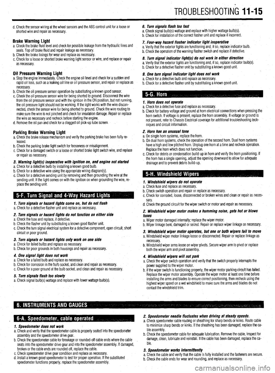
TROUBLESHOOTING 1145
d. Check the sensor wiring at the wheel sensors and the ABS control unit for a loose or
shorted wire and repair as necessary.
Brake Warninu Liaht a. Check the brakefluid~evel and check for possible leakage from the hydraulic lines and
seals. Top off brake fluid and repair leakage as necessary.
b. Check the brake linings for wear and replace as necessary.
c. Check for a loose or shorted brake warning light sensor or wire, and replace or repair
as necessary.
Oil Pressure Warning Light a. Stop the engine immediately. Check the engine oil level and check for a sudden and
rapid oil loss, such as a leaking oil line or oil pressure sensor, and repair or replace as
necessary.
b. Check the oil pressure sensor operation by substituting a known good sensor.
c. Check the oil pressure sensor wire for being shorted to ground. Disconnect the wire
from the oil pressure sensor and with the ignition in the ON position, but not running,
the oil pressure light should not be working. If the light works with the wire discon-
nected, check the sensor wire for being shorted to ground. Check the wire routing to
make sure the wire is not pinched and check for insulation damage. Repair or replace
the wire as necessary and recheck before starting the engine.
d. Remove the oil pan and check for a clogged oil pick-up tube screen.
Parking Brake Warning Light a. Check the brake release mechanism and verify the parking brake has been fully re-
leased.
b. Check the parking brake light switch for looseness or misalignment.
c. Check for a damaged switch or a loose or shorted brake light switch wire, and replace
or repair as necessary.
3. Warning li#ht(s) inoperative with iflnition on,
and engine not started
a. Check for a defective bulb by installing a known good bulb.
b. Check for a defective wire using the appropriate wiring diagram(s).
c. Check for a defective sending unit by removing and then grounding the wire at the
sending unit. If the light comes on with the ignition on when grounding the wire, re-
place the sending unit.
1. Turn siflnais or hazard iiflhts come on, but do not flash
a. Check for a defective flasher unit and replace as necessary.
2. Turn signals or hazard iiflhts do not function on either side
a. Check the fuse and replace, if defective.
b. Check the flasher unit by substituting a known good flasher unit.
c. Check the turn signal electrical system for a defective component, open circuit, short
circuit or poor ground.
3. Turn siflnais or hazard lights only work on one side
a. Check for failed bulbs and replace as necessary.
b. Check for poor grounds in both housings and repair as necessary.
4. One siflnai light does not work
a. Check for a failed bulb and replace as necessary.
b. Check for corrosion in the bulb socket, and clean and repair as necessary.
c. Check for a poor ground at the bulb socket, and clean and repair as necessary.
5. Turn signals flash too slowly
a. Check signal bulb(s) wattage and replace with lower wattage bulb(s). 6. Turn signals flash too fast
a, Check signal bulb(s) wattage and replace with higher wattage bulb(s).
b. Check for installation of the correct flasher unit and replace if incorrect.
7. Four-way hazard flasher indicator iiflhi inoperative
a. Verify that the exterior lights are functioning and, if so, replace indicator bulb.
b. Check the operation of the warning flasher switch and replace if defective.
0. Turn signal indicator ii#ht(s) do not work in either direction
a. Verify that the exterior lights are functioning and, if so, replace indicator bulb(s).
b. Check for a defective flasher unit by substituting a known good unit.
9. One turn signal indicator liflht does not work
a. Check for a defective bulb and replace as necessary.
b. Check for a defective flasher unit by substituting a known good unit.
1. Horn does not operate
a. Check for a defective fuse and replace as necessary.
b. Check for battery voltage and ground at horn electrical connections when pressing the
horn switch. If voltage is present, replace the horn assembly. If voltage or ground is
not present, refer to Chassis Electrical coverage for additional troubleshooting tech-
niques and circuit information.
2. Horn has an unusual tone
a. On single horn systems, replace the horn.
b. On dual horn systems, check the operation of the second horn. Dual horn systems
have a high and low pitched horn. Unplug one horn at a time and recheck operation.
Replace the horn which does not function.
c. Check for debris or condensation build-up in horn and verify the horn positioning. If
the horn has a single opening, adjust the opening downward to allow for adequate
drainage and to prevent debris build-up.
1. Windshield wipers do not operate
a. Check fuse and replace as necessary.
b. Check switch operation and repair or replace as necessary.
c. Check for corroded, loose, disconnected or broken wires and clean or repair as neces-
sary.
d. Check the ground circuit for the wiper switch or motor and repair as necessary.
2. Windshield wiper motor makes a humming noise, gets hot or blows
fuses
a. Wiper motor damaged internally; replace the wiper motor.
b. Wiper linkage bent, damaged or seized. Repair or replace wiper linkage as necessary.
3. Windshield wiper motor operates, but one or both wipers fail to move
a. Windshield wiper motor linkage loose or disconnected. Repair or replace linkage as
necessary.
b. Windshield wiper arms loose on wiper pivots. Secure wiper arm to pivot or replace
both the wiper arm and pivot assembly.
4. Windshield wipers will not park
a. Check the wiper switch operation and verify that the switch properly interrupts the
power supplied to the wiper motor.
b. If the wiper switch is functioning properly, the wiper motor parking circuit has failed.
Replace the wiper motor assembly. Operate the wiper motor at least one time before
installing the arms and blades to ensure correct positioning, then recheck using the
highest wiper speed on a wet windshield to make sure the arms and blades do not
contact the windshield trim.
1. Speedometer does not work to minimize sharp bends or kinks.
If the sheathing has been
damaged, replace the ca-
a. Check and verify that the speedometer cable is properly seated into the speedometer ble assembly.
assembly and the speedometer drive gear. b. Check the speedometer cable for adequate lubrication. Remove the cable, inspect for
b. Check the speedometer cable for breakage or rounded-off cable ends where the cable damage, clean, lubricate and reinstall. If the cable has been damaged, replace the ca-
seats into the speedometer drive gear and into the speedometer assembly. If damaged, ble.
broken or the cable ends are rounded off, replace the cable.
c. Check speedometer drive gear condition and replace as necessary. 3. Speedometer works intermittently
d. Install a known good speedometer to test for proper operation. If the substituted a. Check the cable and verify that the cable is fully installed and the fasteners are secure.
speedometer functions properly, replace the speedometer assembly. b. Check the cable ends for wear and rounding, and replace as necessary.
Page 407 of 408
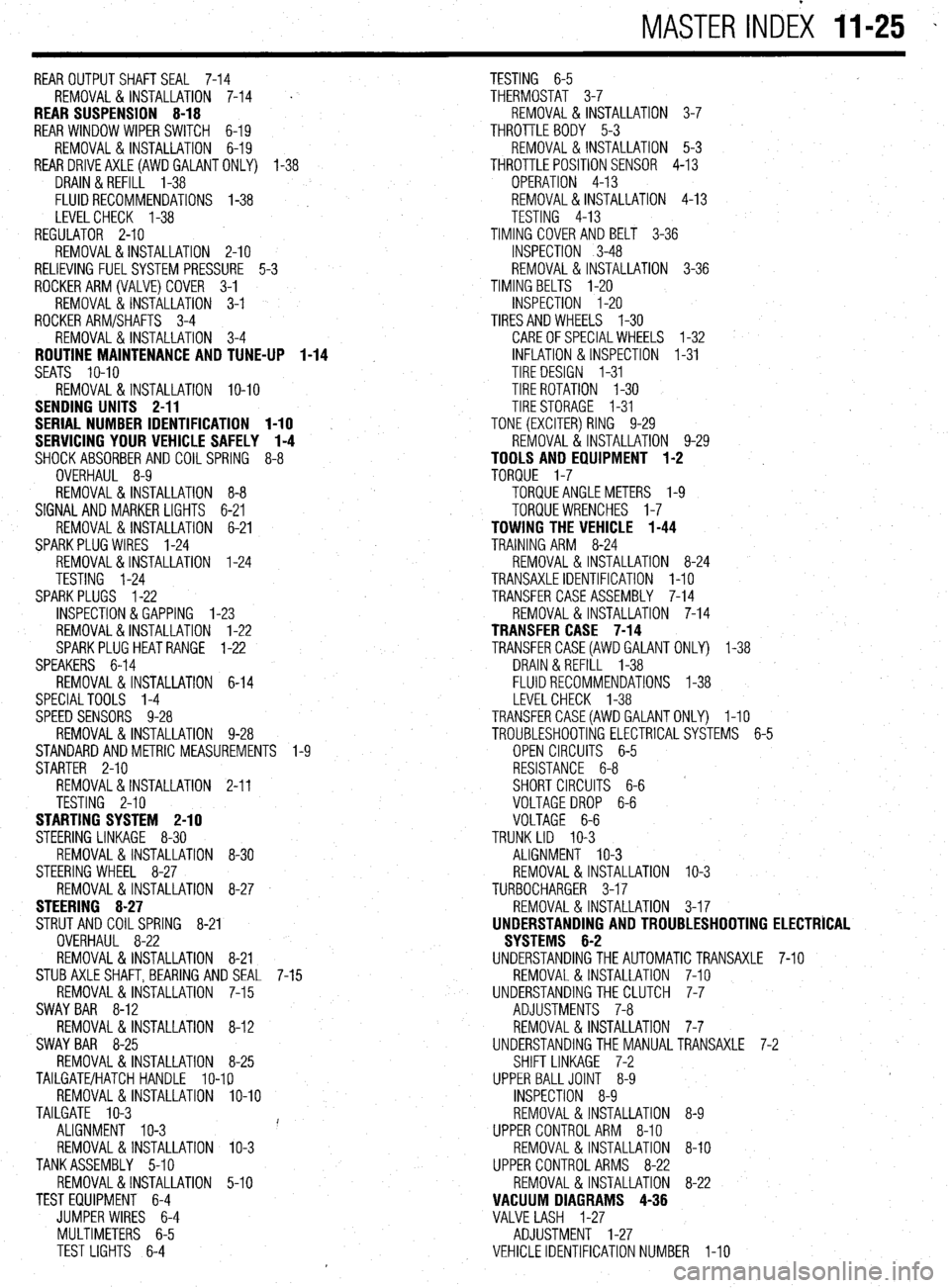
MASTER INDEX 11-25 -
REAROUTPUTSHAFTSEAL 7-14
TESTING 6-5
REMOVAL & INSTALLATION 7-14
' THERMOSTAT 3-7
REAR SUSPENSION 8-18 REMOVAL & INSTALLATION 3-7
REAR WINDOW WIPER SWITCH 6-19 THROTTLE BODY 5-3
REMOVAL&INSTALLATION 6-19 REMOVAL & INSTALLATION 5-3
REARDRlVEAXLE(AWDGALANTONLY) l-38
THROTTLEPOSITIONSENSOR 4-13
DRAIN &REFILL 1-38
OPERATION 4-13
FLUIDRECOMMENDATIONS 1-38 , REMOVAL&INSTALLATION 4-13
LEVELCHECK l-38
TESTING 4-13
REGULATOR 2-10 TIMING COVERAND BELT 3-36
REMOVAL&INSTALLATION 2-10
INSPECTION 3-48
RELIEVING FUELSYSTEM PRESSURE 5-3 REMOVAL & INSTALLATION 3-36
ROCKERARM(VALVE)COVER 3-1
TIMING BELTS l-20
REMOVAL & INSTALLATION 3-1
INSPECTION I-20
ROCKER ARM/SHAFTS 3-4
TIRESANDWHEELS I-30
REMOVAL & INSTALLATION 3-4
CAREOFSPECIALWHEELS l-32
ROUTINE MAINTENANCE AND TUNE-UP 1-14 INFLATION & INSPECTION I-31
SEATS IO-IO
TIRE DESIGN I-31
REMOVAL&INSTALLATION IO-IO TIRE ROTATION I-30
SENDING UNITS 2-11
TIRESTORAGE I-31
SERIAL NUMBER IDENTIFICATION l-10
TONE (EXCITER) RING 9-29
SERVICING YOUR VEHICLE SAFELY I-4
REMOVAL & INSTALLATION 9-29
SHOCKABSORBERAND COILSPRING 8-8
TOOLS AND EQUIPMENT 1-2
OVERHAUL 8-9
TORQUE 1-7
REMOVAL&INSTALLATION 8-8 TORQUEANGLEMETERS l-9
SIGNAL AND MARKER LIGHTS 6-21
TORQUEWRENCHES l-7
REMOVAL & INSTALLATION 6-21
TOWING THE VEHICLE 1-44
SPARKPLUG WIRES 1-24
TRAINING ARM 8-24
REMOVAL&INSTALLATION 1-24
REMOVAL & INSTALLATION 8-24
TESTING 1-24
TRANSAXLEIDENTIFICATION I-10
SPARKPLUGS l-22
TRANSFER CASE ASSEMBLY 7-14
INSPECTION &GAPPING l-23
REMOVAL & INSTALLATION 7-14
REMOVAL&INSTALLATION 1-22
TRANSFER CASE 7-14
SPARKPLUGHEATRANGE 1-22
TRANSFERCASE(AWD GALANT ONLY) 1-38
SPEAKERS 6-14
DRAIN &REFILL 1-38
REMOVAL & INSTALLATION 6-14
FLUIDRECOMMENDATIONS 1-38
SPECIALTOOLS 1-4
LEVELCHECK 1-38
SPEED SENSORS 9-28
TRANSFERCASE(AWDGALANTONLY) I-10
REMOVAL & INSTALLATION 9-28
TROUBLESHOOTING ELECTRICALSYSTEMS 6-5
STANDARDANDMETRIC MEASUREMENTS l-9
OPEN CIRCUITS 6-5
STARTER 2-10
RESISTANCE 6-8
REMOVAL&INSTALLATION 2-11
SHORT CIRCUITS 6-6
TESTING 2-10
VOLTAGEDROP 6-6
STARTING SYSTEM 2-10
VOLTAGE 6-6
STEERING LINKAGE 8-30
TRUNK LID IO-3
REMOVAL &INSTALLATION 8-30
ALIGNMENT IO-3
STEERING WHEEL 8-27
REMOVAL & INSTALLATION IO-3
REMOVAL &INSTALLATION 8-27
TURBOCHARGER 3-17
STEERING 8-27
REMOVAL & INSTALLATION 3-17
STRUT AND COIL SPRING
8-21
UNDERSTANDING AND TROUBLESHOOTING ELECTRICAL
OVERHAUL 8-22
SYSTEMS 6-2
REMOVAL & INSTALLATION 8-21
UNDERSTANDINGTHEAUTOMATICTRANSAXLE 7-10
STUBAXLESHAFT,BEARlNG AND SEAL 7-15
REMOVAL & INSTALLATION 7-10
REMOVAL&INSTALLATION 7-15
UNDERSTANDINGTHECLUTCH 7-7
SWAY BAR 8-12
ADJUSTMENTS 7-8
REMOVAL 8, INSTALLATION 8-12
REMOVAL&INSTALLATION 7-7
SWAY BAR 8-25
UNDERSTANDINGTHE MANUALTRANSAXLE 7-2
REMOVAL&INSTALLATION 8-25
SHIFT LINKAGE 7-2
TAILGATE/HATCH HANDLE lo-19
UPPER BALLJOINT 8-9
REMOVAL &INSTALLATION lo-10
INSPECTION 8-9
TAILGATE IO-3
REMOVAL &INSTALLATION 8-9
ALIGNMENT IO-3 i'
UPPER CONTROLARM 8-10
REMOVAL & INSTALLATION IO-3
REMOVAL & INSTALLATION 8-10
TANKASSEMBLY 5-10
UPPER CONTROL ARMS 8-22
REMOVAL&INSTALLATION 5-10
REMOVAL & INSTALLATION 8-22
TEST EQUIPMENT 6-4
VACUUM DIAGRAMS 4-36
JUMPER WIRES 6-4
VALVE LASH 1-27
MULTIMETERS 6-5
ADJUSTMENT 1-27
TEST LIGHTS 6-4
VEHICLE IDENTIFICATION NUMBER I-10
Page 408 of 408
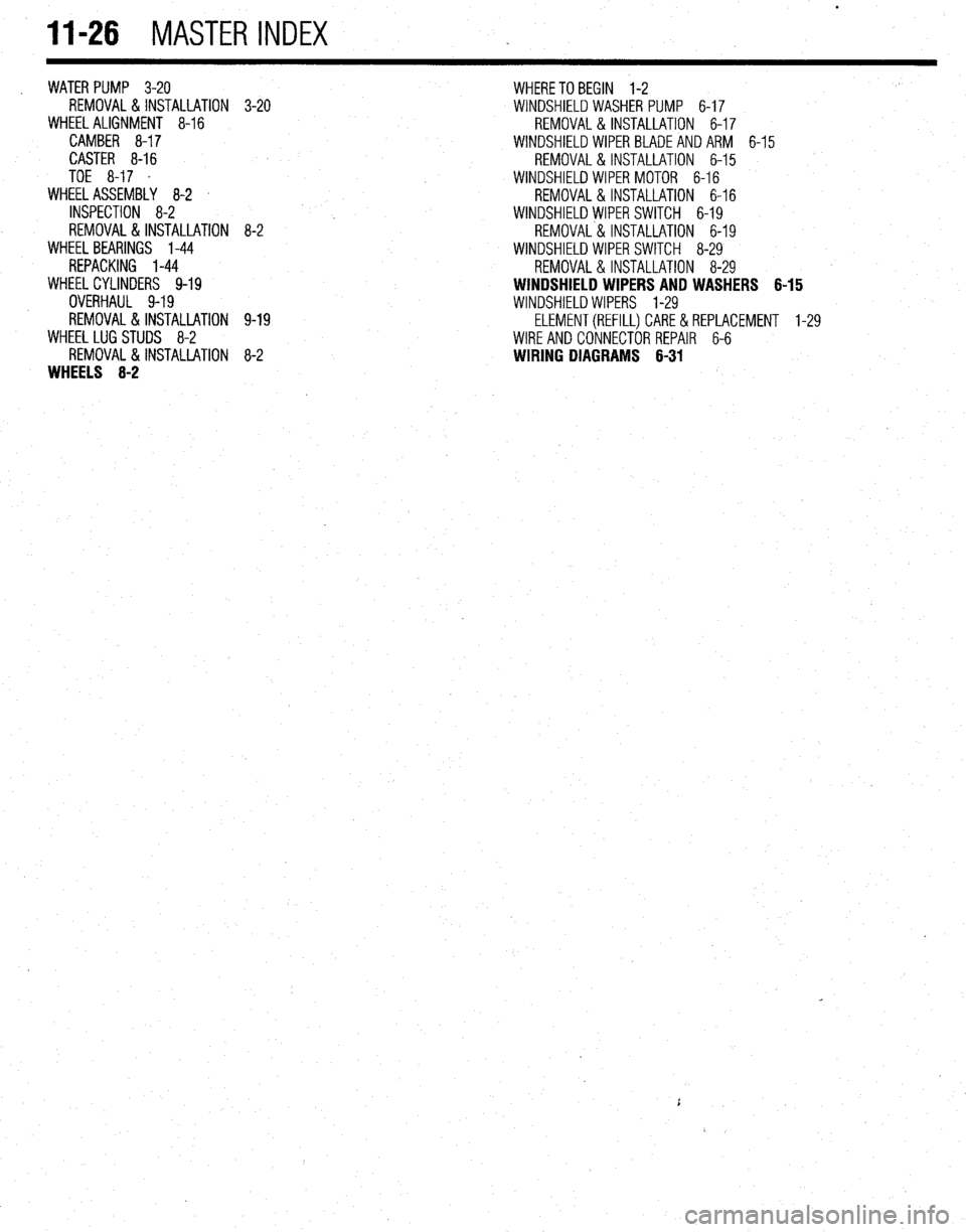
11-26 MASTER INDEX
WATER PUMP 3-20
REMOVAL&INSTALLATION
WHEEL ALIGNMENT 8-16
CAMBER 8-17
CASTER 8-16
TOE 8-17 .
WHEEL ASSEMBLY 8-2 '
INSPECTION 8-2
REMOVAL&INSTALLATION
WHEEL BEARINGS 1-44
REPACKING l-44
WHEELCYLINDERS 9-19
OVERHAUL 9-19
REMOVAL&INSTALLATION
WHEEL LUG STUDS 8-2
REMOVAL&INSTALLATION
WHEELS 8-2 3-20 WHERETO BEGIN 1-2
WINDSHIELD WASHER PUMP 6-17
REMOVAL & INSTALLATION 6-17
WINDSHIELD WIPER BLADE AND ARM 6-15
REMOVAL & INSTALLATION 6-15
WINDSHIELD WIPER MOTOR 6-16
REMOVAL &INSTALLATION 6-16
8-2
9-19
8-2 WINDSHIELD WIPER SWITCH 6-19
REMOVAL & INSTALLATION 6-19
WINDSHIELD WIPER SWITCH 8-29
REMOVAL & INSTALLATION 8-29
WINDSHIELD WIPERS AND WASHERS 6-15
WINDSHIELD WIPERS l-29
ELEMENT(REFILL)CARE&REPLACEMENT 1-29
WIRE AND CONNECTOR REPAIR 6-6
WIRING DIAGRAMS 6-31