Page 89 of 408

3-28 ENGINEANDENGINEOVERHAUL
lntsltaelde Front of engine c3
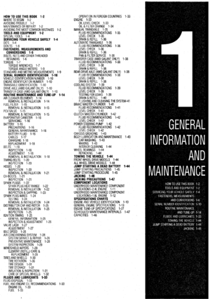
Fig. 125 Cylinder head bolt removal se- Fig. 127 Grasp the cylinder head and lift it
off the engine block with the manifolds at-
ig. 126 A magnet can be extremely help- tached. It is a good idea to use a helper for
quence-2.41(4664) engine I ful when removing the cylinder head bolts 1 1 this, as the assembly is very heavy
93153pOO Fig. 128 Remove the cylinder head gasket 33153p4!3 Fig, 129 Thoroughly clean the gasket sur- Fig. 130 Also, make sure to thoroughly
clean the engine block mating surfaces be-
from the block
faces of the cylinder head fore reassembling the engine
l Intake Air Temperature (IAT) sensor l Throttle Position (TP) sensor
: /I;%;,; rZ;Z;;(lAC) motor 23. Inspect the cylinder head bolt length prior to
installation. If the length exceeds 3.91 in. (99.4mm),
the bolt must be replaced. Install the washer onto the
bolt so the chamfer on the washer faces towards the
l Ignition coil head of the bolt. l Camshaft Position (CMP) sensor 24. Carefully install the cylinder head on the l Exhaust Gas Recirculation (EGR) solenoid block and tighten the cylinder head bolts as follows:
valve a. Following the proper tightening sequence,
11. Remove the spark plug wire cover and wires. tighten the cylinder head bolts to 58 ft. Ibs. (78
12. At the thermostat case assembly, remove the Nm).
coolant hoses and unbolt the thermostat case from b. Loosen all bolts completely.
the engine. c. Torque bolts to 15 ft. Ibs. (20 Nm). ’
Fig. 131 Cylinder head bolt installation se-
13. Remove the upper timing belt cover d. Tighten bolts an additional 1/4 turn.
14. Align all timing marks. e. Tighten bolts an additional 1/4 turn.
15. Secure the timina belt to the camshaft 25. Install the new exhaust pipe aasket and con-
iliiL.-
5.
9. Disconnect and plug the fuel return hose. Disconnect the accelerator cable. Remove the
cable mounting brackets and position the cable
10. Label and detach the connectors from the fol- aside.
lowing components: 6. Remove the breather hose.
* A$ compressor
* Power steering pressure switch ‘7. Label and disconnect the vacuum lines at the
* Heated Oxygen (HO$) sensor tree body.
* Engine Coolant Temperature (ECT) gauge . 8. D&connect and plug the high pressure fuel
sender
lint3
l
ECT sensor l Manifold Absolute Pressure (MAP) sensor sprocket with cord or a wire tie.
fold. Discard the gasket, 16. Remove the camshaft sprocket.
20. Loosen the cylinder head mounting bolts in 3 17.
steps, starting from the outside and working inward. Remove the valve cover and the half-round
seal.
Lift off the cylinder head assembly and remove the 18. Disconnect the intake manifold stay bracket
head gasket.
To install: from the intake manifold.
21. Thoroughly clean the mating surfaces of the 19. Remove the exhaust pipe self-locking nuts
head and block. and separate the exhaust pipe from the exhaust mani-
22. Place a new head gasket on the cylinder
block with the identification marks at the front top
(upward) position. Do not use sealer on the gasket. nect the exhaust pipe to the manifold. Tighten the
portions of the belt-side of the new gasket. Install thr bolts to 33 ft. Ibs. (44 Nm).
valve cover. 26.
29. Install the thermostat case and tighten the
Install the camshaft sprocket with the timing mounting bolts to 18 ft. Ibs. (24 Nm).
belt attached. Remove the cord or wire tie.
30. Install the upper timing belt cover. 27. Connect the coolant hoses to the thermostat
31. Connect the intake manifold stay and tighten case.
the mounting bolts to 22 ft. Ibs. (30 Nm). 28.
32. Attach the connectors to the following com- Apply sealer to the perimeter of the half-
round seal and to the lower edges of the half-round
ponents: l A/C compressor l Power steering pressure switch
Page 90 of 408

ENGINEANDENGINEOVERHAUL 3-29
l HOzS sensor l ECT gauge sender l ECT sensor l MAP sensor l IAT sensor l TP sensor l IAC motor l injector harness l ignition coil l CMP sensor l EGR solenoid valve
33. Install the spark plug wires and cover,
34. Replace the O-rings and connect the fuel
lines.
35. Install the air cleaner and intake hose. Con-
nect the breather hose.
36. Fill the cooling system.
37. Connect the negative battery cable
3.01 DDHC Engine
ti See Figures 132 and 133
1. Relieve fuel system pressure. Disconnect the
negative battery cable.
2. Drain the cooling system.
Never open, service or drain the radiator or
cooling system when hot; serious burns can
occur from the steam and hot coolant. Also,
when draining engine coolant, keep in mind
that cats and dogs are attracted to ethylene
glycol antifreeze and could drink any that is
left in an uncovered container or in puddles
on the ground. This will prove fatal in suffi-
cient quantltles. Always drain coolant into a
sealable container. Coolant should be reused
unless it is contaminated or is several years
old.
3. Remove the air intake hoses.
4. Remove air intake plenum and intake mani-
fold.
5. Remove the exhaust manifold.
6. Remove the timing belt. Refer to the timing
belt procedure in this section.
7. Remove the breather hose.
8. Remove the spark plug wire center cover and
remove the spark plug wires.
9. Remove the rocker covers.
10. Remove the intake camshaft sprockets.
11. Remove the rear timing belt cover.
12. Remove the ignition coil assembly.
13. Disconnect all water hoses from the thermo-
stat housing and remove the housing.
14. Disconnect the water inlet from the front
head.
15. Loosen the cylinder head mounting bolts in
the reverse of the torque sequence and loosen the
bolts in three steps. Lift off the cylinder head assem-
bly and remove the head gasket.
To install: 16. Thoroughly clean the sealing surfaces of the
head and block.
17. Place a new head gasket on the cylinder
block with the identification marks in the front top
(upward) position. Do not use sealer on the gasket,
18. Carefully install the cylinder head on the
block. Be sure the head bolt washers are installed
with the chamfered edge upward. Using three even
steps, torque the head bolts in sequence, to 76-83 ft.
Ibs. (105-115 Nm).
@ Timing belt side
7923PG26 :ig. 132 Tighten the cylinder head bolts ac-
:ording to the sequence shown-3.01
SDHC and DDHC) engines
Rear bank
[::od
04
~8 01
Front bank
'1 "8
509 010 011 6
1.03 07 02 7923ffi25 Fig. 133 Rocker cover bolt torque se-
quence-Diamante 3.OL DDHC engine
19. Install new O-ring and connect the water inlet
to the head. Tighten the mounting bolt to 9-11 ft. Ibs
(12-15 Nm).
20. Replace the gaskets and install the thermostat
housing. Tighten the mounting bolts to 12-14 ft. Ibs.
(17-20 Nm).
21. Using new hose clamps, connect the hoses to
the thermostat housing.
22. Install the Ignition coil and torque the mount-
ing bolts to 7 ft. Ibs. (10 Nm).
23. Install the rear timing belt cover and torque
the mounting bolts to 17 ft. Ibs. (24 Nm).
24. Install the intake camshaft sprockets. Tighten
the retaining bolt to 65 ft. Ibs. (90 Nm).
25. Apply sealer to the lower edges of the valve
cover. Tighten the bolts in the proper sequence to
44-51 inch Ibs. (5-6 Nm).
26. Connect the spark plug wires and install the
center cover. Tighten the bolts that secure the center
cover to 27 inch Ibs. (3 Nm)
27. Install the breather hose.
28. Install the timing belt. Refer to the timing belt
procedure in this section,
29. Install the exhaust manifold assembly.
30. Using all new gaskets, install the intake man-
ifold and air intake plenum.
31. Install the air intake hoses.
32. Change the engine oil and oil filter. 33. Fill the system wrth coolant.
34. Connect the negabve battery cable.
35. Adjust the accelerator cable.
36. Start the engine.
37. Check and adjust the idle speed and ignition
timing.
38. Once the vehicle has cooled, recheck the
coolant level.
3.OL SDHC Engine
# See Figure 132
1. Relieve the fuel system pressure.
2. Disconnect the negative battery cable.
3. Drain the cooling system.
Never open, service or drain the radiator or
cooling system when hot; serious burns can
occur from the steam and hot coolant. Also,
when draining engine coolant, keep in mind
that cats and dogs are attracted to ethylene
alvcol antifreeze and could drink any that is
Left in an uncovered container or in puddles
on the ground. This will Drove fatal in suff i-
cient quantities. Always drain coolant into a
sealable container. Coolant should be reused
Unless it is Contaminated or is several years
old.
4. Remove the air intake hose.
5. Remove the exhaust manifold.
6. Remove the air intake plenum and intake
manifold.
7. Remove the timing belt. Refer to the timing
belt procedure in this section.
8. Remove the camshaft sprockets and the rear
timing belt cover.
9. Remove the power steering pump bracket. If
removing the rear head, remove the alternator brace.
10. Disconnect the water inlet pipe.
11. Remove the purge pipe assembly.
12. Remove the valve cover,
13. Using the reverse sequence of the installation
sequence, loosen the cylinder head mounting bolts in
three steps. Lift off the cylmder head assembly and
remove the head gasket.
To install: 14. Thoroughly clean the sealing surfaces of the
head and block.
15. Place a new head gasket on the cylinder
block making sure the identification mark on the
cylrnder head gasket is in the front top (upward) loca-
tion. Do not use sealer on the gasket,
16. Carefully install the cylinder head on the
block. Be sure the head bolt washers are installed
with the chamfered edge upward. Using three even
steps, torque the head bolts in sequence, to 7683 ft.
Ibs. (105-115 Nm).
17. Apply sealer to the lower edges of the half-
round portions and install the valve cover. Tighten
valve cover bolts to 7 ft. Ibs. (9 Nm).
18. Install the purge pipe assembly.
19. Connect the water inlet pipe.
20. Install the power steering pump bracket and
alternator brace.
21. Install the rear timing belt cover and camshaft
sprockets. Torque the retaining bolt to 65 ft. Ibs. (90
Nm).
22. Install the timing belt. Refer to the timing belt
procedure in this section.
Page 91 of 408

.
3-30 ENGINEANDENGINEOVERHAUL
23. Using all new gaskets, install the intake man-
ifold, air intake plenum and exhaust manifold.
24. Install the air intake hose.
25. Fill the system with coolant.
26. Connect the negative battery cable.
27. Start the engine.
28. Check and adjust the idle speed and ignition
timing.
29. Once the vehicle has cooled, recheck the
coolant level.
3.51 Engine
ti See Figure 134
1. Disconnect the negative battery cable.
2. Drain the engine coolant
Never open, service or drain the radiator or
cooling system when hot; serious burns can
occur from the steam and hot coolant. Also,
when draining engine coolant, keep in mind
that cats and dogs are attracted to ethylene
glycol antifreeze and could drink any that is
left in an uncovered container or in puddles
on the ground. This will prove fatal in suffi-
cient quantities. Always drain coolant into a
sealable container. Coolant should be reused
unless it is contaminated or is several years
old.
3. Remove the timing belt. Refer to the timing
belt procedure in this section.
4. Remove the intake and exhaust manifolds.
5. Remove the spark plug wires.
6. Remove the cylrnder head covers.
7. Remove the timing belt rear center cover.
8. Loosen the cylinder head bolts gradually in
three stages, in the opposite of the installation se-
quence.
9. Remove the cylinder head.
To install: 10. Clean the cylinder head and mounting sur-’
face on the engine block.
11. Install the cylinder head using a new gasket.
12. Tighten the bolts in sequence using three
stages to 76-83 ft. Ibs. (103-113 Nm).
13. Install the timing belt rear center cover.
14. Install the cylinder head covers using new
gaskets. Tighten the bolts to 2-3 ft. Ibs. (334 Nm).
15. Install the spark plug wires,
16. Install the intake and exhaust manifolds,
17. Install the timing belt. Refer to the timing belt
procedure in this section.
7923PGD2 Fig. 134 Cylinder head bolt tightening se-
quence-3.5L engine
18. Install any remaining components.
19. Refill the cooling system.
20. Connect the negative battery cable.
REMOVAL &INSTALLATION
1.5L Engine
p See Figure 135
1. Disconnect the negative battery cable.
2. Drain the engine oil.
The EPA warns that prolonged contact with
used engine oil may cause a number of skin
disorders, including cancer! You should
make every effort to minimize your exposure
to used engine oil. Protective gloves should
be worn when changing the oil. Wash your
hands and any other exposed skin areas as
soon as possible after exposure to used en-
gine oil. Soap and water, or waterless hand
cleaner should be used.
3. Remove the bell housing lower cover.
4. Remove the oil pan retainer bolts. Tap the oil
pan with a rubber mallet to break seal.
*Do not use a prytool when removing the oil
pan. If available, oil pan remover tool
MD998727 or equivalent may be used to
break the seal. To install:
5. Clean all gasket surfaces of the cylinder
block and the oil pan.
6. Apply sealant to the gasket surfaces of the oil
pan.
7. Install the oil pan onto the cylinder block
within 15 minutes after applying sealant. Install the
fasteners and tighten to 60 inch Ibs. (7 Nm).
8. Install the bell housing cover.
9. Install the oil drain plug with a new seal and
tighten to 29 ft. Ibs. (40 Nm).
10. Lower the vehicle and fill the crankcase to the
proper level with clean engine oil.
Operating the engine without the proper
amount and type of engine oil will result in
severe engine damage.
11. Connect the negative battery cable. Start the
engine and check for leaks.
1.8L Engine
# See Figure 136
1. Disconnect the negative battery cable.
2. Raise the vehicle and support safely.
3. Remove the oil pan drain plug and drain the
engine oil.
The EPA warns that prolonged contact with
used engine oil may cause a number of skin
disorders, including cancer! You should
make every effort to minimize your exposure
to used engine oil. Protective gloves should
I Fig. 135 Oil pan and related components-Mirage 1.5L (4615) engine
Page 92 of 408

ENGINEANDENGINEOVERHAUL 3-31
I,.s; engine g3i53g26
Fig 136 Oil pan and related components-
be worn when changing the oil. Wash your
hands and any other exposed skin areas as
soon as possible after exposure to used en-
gine oil. Soap and water, or waterless hand
cleaner should be used.
4. Disconnect and lower the exhaust pipe from
the engine manifold.
5. Remove the bell housing lower cover.
6. Remove the oil pan retainer bolts and remove
the oil pan.
*Do not use a prytool when removing the oil
pan. If available, oil pan remover tool
MD998727 or equivalent may be used break
the seal.
To install:
7. Clean all gasket surfaces of the cylinder
block and the oil pan.
8. Apply sealant around the gasket surfaces of
the oil pan.
9. Install the oil pan onto the cylinder block
within 15 minutes after applying sealant. Install the
fasteners and tighten to 60 inch Ibs. (5 Nm).
10. install the bell housing cover.
11. Connect the exhaust pipe to the engine mani-
fold with new gasket in place. Tighten the exhaust
pipe to manifold flange nuts to 33 ft. Ibs. (45 Nm).
Install and tighten the support bolt to 18 ft. Ibs. (25
Nm).
12. Install the oil drain plug and tighten to 29 ft.
Ibs. (40 Nm).
13. Fill the crankcase to the proper level.
Operating the engine without the proper
amount and type of engine oil will result in
severe engine damage.
14. Connect the negative battery cable. Start the
engine and check for leaks.
1.6L and 2.OL Engines
FRONT WHEEL DRIVE
ti See Figures 137 and 138
1. Disconnect the negative battery cable.
2. Raise the vehicle and support safely.
3. Remove the oil pan drain plug and drain the
engine oil.
93153gza Fig. 137 Oil pan and related components-
2.OL SOHC engine
93153g29 Fig. 138 Oil pan and removal for FWD and
AWD l.liL and 2.OL DDHC enoines
The EPA warns that prolonged contact with
used engine oil may cause a number of skin
disorders, including cancer! You should
make every effort to minimize your exposure
to used engine oil. Protective gloves should
be worn when changing the oil. Wash your
hands and any other exposed skin areas as
soon as possible after exposure to used en-
gine oil. Soap and water, or waterless hand
cleaner should be used.
4. Disconnect and lower the exhaust pipe from
the engine manifold.
5. Using the appropriate equipment, support the
weight of the engine.
6. Remove the retainer bolts and the center
crossmember,
7. Remove the oil pan bolts. Using special tool
MD998727, tap in between the engine block and the
oil pan.
*Do not use a chisel, screwdriver or similar
tool when removing the oil pan. Damage to
engine components may occur.
8. Inspect the oil pan for damage and cracks.
Replace if faulty. While the pan is removed, inspect
the oil screen for clogging, damage and cracks. Re-
place if faulty.
To install: 9. Using a wire brush or other tool, scrape clean
all gasket surfaces of the cylinder block and the oil
pan so that all loose material is removed. Clean seal-
ing surfaces of all dirt and oil.
10. Apply sealant around the gasket surfaces of
the oil pan in such a manner that all bolt holes are
circled and there is a continuous bead of sealer
around the entire perimeter of the oil pan.
*The continuous bead of sealer should be
applied in a bead approximately 0.16 in.
(4mm) in diameter.
11. Install the oil pan onto the cylinder block
within 15 minutes after applying sealant. Install the
fasteners and tighten to 4-6 ft. Ibs. (G8 Nm).
12. Install the crossmember and tighten the
mounting bolts to 72 ft. Ibs. (100 Nm).
13. Connect the exhaust pipe to the engine mani-
fold with new gasket In place. Tighten the exhaust
pipe to manifold flange nuts to 29 ft. Ibs. (40 Nm)
14. Install the oil drain plug and tighten to 33 ft.
Ibs.
15. Lower the vehicle and fill the crankcase to the
proper level with clean engine oil.
Operating the engine without the proper
amount and type of engine oil will result in
severe engine damage.
16. Connect the negative battery cable.
17. Start the engine and check for leaks.
ALL WHEEL DRIVE
ti See Figure 138
1. Disconnect the negative battery cable.
2. Raise the vehicle and support safely.
3. Remove the oil pan drain plug and drain the
engine oil.
The EPA warns that prolonged contact with
used engine oil may cause a number of skin
disorders, including cancer! You should
make every effort to minimize your exposure
to used engine oil. Protective gloves should
be worn when changing the oil. Wash your
hands and any other exposed skin areas as
soon as possible after exposure to used en-
gine oil. Soap and water, or waterless hand
cleaner should be used.
4. Disconnect and lower the exhaust pipe from
the engine manifold.
5. Remove the transfer assembly and right dri-
veshaft.
6. Using the appropriate equipment, support the
weight of the engine and remove the center cross-
member.
7. Disconnect the return pipe for the tur-
bocharger from the side of the oil pan.
8. Remove the oil pan bolts. Using special tool
MD998727, tap In between the engine block and the
oil pan.
*Do not use a chisel, screwdriver or similar
tool when removing the oil pan. Damage to
engine components may occur.
Page 93 of 408

.
3-32 ENGINEANDENGINEOVERHAUL
9. Inspect the oil pan for damage and cracks.
Replace if faulty, While the pan is removed, inspect
the oil screen for clogging, damage and cracks, Re-
place if faulty.
To install: 10. Using a wire brush or other tool, scrape clean
all gasket surfaces of the cylinder block and the oil
pan so that all loose material is removed. Clean seal-
ing surfaces of all dirt and oil.
11, Apply sealant around the gasket surfaces of
the oil pan in such a manner that all bolt holes are
circled and there is a continuous bead of sealer
around the entire perimeter of the oil pan.
*The continuous bead of sealer should be
applied in a bead approximately 0.16 in.
(4mm) in diameter.
12. Install the oil pan onto the cylinder block
within 15 minutes after applying sealant. Install the
fasteners and tighten to 4-6 ft. Ibs. (68 Nm).
13. Install the oil return pipe using a new gasket,
if removed. Tighten retainers to 5-7 ft. Ibs. (7-10
Nm).
14. Install the left member and tighten the forward
retainer bolts to 72 ft. Ibs. (100 Nm). Tighten the
rearward left member bolts to 58 ft. Ibs. (80 Nm).
15. Install the transfer assembly and right drive-
shaft.
16. Connect the exhaust pipe from the engine
manifold with new gasket in place. Tighten the ex-
haust pipe to manifold flange nuts to 29 ft. Ibs. (40
Nm).
17. Install the oil drain plug and tighten to 33 ft.
Ibs.
18. Lower the vehicle and fill the crankcase to the
proper level with clean engine oil.
Operating the engine without the proper
amount and type of engine oil will result in
severe enaine damage.
19. Connect the negative battery cable. Start the
engine and check for leaks.
2.4L Engine
) See Figure 139
1, Disconnect the negative battery cable. -
,(L.. K%
2 mM_
-Ip
t 8*t.almcwr
:y&pn
::Elm
93153g30 Fig. 139 Oil pan and related components-
2.4L engine
2. Remove the oil pan drain plug and drain the
engine oil.
The EPA warns that prolonged contact with
used engine oil may cause a number of skin
disorders, including cancer! You should
make every effort to minimize your exposure
to used engine oil. Protective gloves should
be worn when changing the oil. Wash your
hands and any other exposed skin areas as
soon as possible after exposure to used en-
gine oil. Soap and water, or waterless hand
cleaner should be used.
3. Remove the oil dipstick and tube assembly.
4. Detach the Heated Oxygen (HOaS) sensor
connector.
5. Remove the front exhaust pipe from the vehi-
cle.
6. Remove the bell housing cover.
7. Remove the oil pan retainer bolts. Using spe-
cial tool MD998727 or equivalent, tap in between the
engine block and the oil pan.
*Do not use a prytool when removing the oil
pan. Damage to engine components may oc-
cur.
To install:
8. Apply sealant around the gasket surfaces of
the oil pan.
9. Install the oil pan onto the cylinder block
within 15 minutes after applying sealant. Install the
fasteners and tighten to 6 ft. Ibs. (8 Nm).
10. Install the oil drain plug and tighten to 29 ft.
Ibs. (39 Nm).
11. Install the bell housing cover, and tighten the
mounting bolts to 7 ft. Ibs. (9 Nm).
12. Install the front exhaust pipe and tighten the
bolts at the catalytic converter to 36 ft. Ibs. (49 Nm).
Tighten the nuts at the exhaust manifold to 32 ft. Ibs.
(44 Nm).
13. Reconnect the HOPS sensor connector.
Operating the engine without the proper
amount and type of engine oil will result in
severe engine damage.
15. Connect the negative battery cable. Start the
engine and check for leaks.
3.OL Engines
u See Figure 140
1. Disconnect the negative battery cable.
2. Remove the oil pan drain plug and drain the
The EPA warns that prolonged contact with
used engine oil may cause a number of skin
disorders, including cancer! You should
make every effort to minimize your exposure
to used engine oil. Protective gloves should
be worn when changing the oil. Wash your
hands and any other exposed skin areas as
soon as possible after exposure to used en-
Groove
Hole of bolt 7923PG67 Fig. 140 Oil pan bolt tightening sequence
and application of sealant to the pan-Dia-
mante 3.OL engines
gine oil. Soap and water, or waterless hand
cleaner should be used.
3. Remove the left side crossmember. If
equipped with 4WS, it will also be necessary to re-
move the right side crossmember.
4. Remove the starter motor.
5. Disconnect the roll stopper stay bracket, from
the rear transaxle stay bracket. Remove the both
transaxle stay brackets.
6. Remove the bell housing lower cover.
7. Remove the oil pan mounting bolts. Using
special tool MD998727 or equivalent, separate and
remove the engine oil pan.
To install: 8. Apply a 0.16 in. (4mm) continuous bead of
sealer around the surface of the oil pan.
*Assemble the oil pan to the cylinder block
within 15 minutes after applying the sealant.
9. Install the oil pan mounting bolts. Following
proper sequence, tighten mounting bolts to 48 inch
Ibs. (6 Nm).
10. Install lower bell housing cover and the
starter motor.
11, Install the transaxle stay brackets and connect
the roll stopper bracket.
12. Install the crossmember and tighten the
mounting bolts to 43-51 ft. Ibs. (60-70 Nm).
13. Fill the engine with the proper amount of oil.
.
Operating the engine without the proper
amount and type of engine oil will result in
severe engine damage.
14. Connect the negative battery cable and check
for leaks.
3.5L Engine
p See Figures 141, 142, and 143
1, Disconnect the negative battery cable.
2. Drain the engine oil.
The EPA warns that prolonged contact with
used engine oil may cause a number of skin
disorders, includina cancer! You should
make eve’ry effort to minimize your exposure
Page 94 of 408

ENGINEANDENGINEOVERHAUL 3-33
7923PG68 Fig. 141 Install a bolt in the threaded hole
to force the oil pan from the engine block-
3.5L engine
15
16
Groove
Hole of bolt 7923PG69 Fig. 142 Apply sealant and tighten the bolts
In the order shown-3.51 engine, upper oil
Ian shown
View from above
Flange bolt tightening sequence
6 2 4
7923PG70 :ig. 143 Apply sealant and tighten the bolts
in the order shown-3.51 engine, lower oil
pan shown
to used engine oil. Protective gloves should
be worn when changing the oil. Wash your
hands and any other exposed skin areas as
soon as possible after exposure to used en-
gine oil. Soap and water, or waterless hand
cleaner should be used.
3. Remove the mounting boltsfrom the lower
oil pan. 4. Place a block of wood against the side of the
pan and tap the block with a hammer to break the
seal and remove the lower pan.
5. Remove the starter.
6. Remove the dipstick tube.
7. Unbolt the upper oil pan.
Do not pry or use seal breaker tool to remove
the oil pan. Damage to the aluminum surface
can result.
8. Screw a bolt into the threaded hole to force
the oil pan from the engine block and remove the
pan.
9. Remove the bolt used to remove the pan.
To install:
10. Clean and degrease the sealing surfaces of
the upper oil pan and engine block.
11. Apply a bead of sillcone sealant along the
mounting surface of the upper oil pan.
12. Install the upper oil pan. Tighten the bolts in
sequence to 4 ft Ibs. (6 Nm).
13. Install the dipstick tube using a new O-ring.
14. Install the starter assembly.
15. Clean and degrease the sealing surface of the
lower oil pan.
16. Place a bead of sealant on the mounting sur-
face of the lower
oil pan. Install the lower pan.
Tighten the bolts in sequence to 7-9 ft. Ibs. (10-12
Nm).
17. Install the drain plug using a new washer,
Tighten the drain plug to 29 ft. Ibs (39 Nm).
18. Lower the vehicle and fill the crankcase to the
correct level.
Operating the engine without the proper
amount and type of engine oil will result in
severe engine damage.
19 Connect the negative battery cable.
20. Start the engrne and check for leaks,
REMOVAL & INSTALLATION
1.5L and 1.8L Engines
p See Figures 144 and 145
*Whenever the oil pump is disassembled or
the cover removed, the gear cavity must be
filled with petroleum jelly to seal the pump
and act as a prime. Do not use grease.
1. Drsconnect the negative battery cable.
2. Raise and support the vehicle.
3. Drain the engine oil.
The EPA warns that prolonged contact with
used engine oil may cause a number of skin
disorders, including cancer! You should
make every effort to minimize your exposure
to used engine oil. Protective gloves should
be worn when changing the oil. Wash your
93153927 Fig. 144 Exploded view of the oil pump
mounting-l .5L engine
93153931 Fig. 145 Exploded view of the oil pump
mounting-l.81 engine
hands and any other exposed skin areas as
soon as possible after exposure to used en-
gine oil. Soap and water, or waterless hand
. . . .
cleaner snoutd be used.
4. Support the engine using a suitable device
5. Remove the front engme mount bracket and
accessory drive belts.
6. Remove timing belt upper and lower covers.
7. Remove the timing belt and crankshaft
sprocket. Refer to the timing belt procedure in this
section.
8. Remove the oil pan and remove the oil
screen.
Page 95 of 408

3-34 ENGINEANDENGINEOVERHAUL
9. Remove the front cover mounting bolts. Note
the lengths of the mounting bolts as they are re-
moved for proper installation.
10. Remove the front case assembly and oil
pump assembly.
11. Remove the oil pump cover.
12. Remove the inner and outer gears from the
front case.
To install 13. Remove all gasket material from the mating
surfaces and clean all parts.
14. Thoroughly coat both oil pump gears with
clean engine oil and install them in the correct direc-
tion of rotation.
15. Install the pump cover and tighten the bolts to
84 inch Ibs. (10 Nm).
16. Coat the relief valve and spring with clean en-
gine oil. Install them and tighten the plug to 33 ft.
Ibs. (45 Nm).
17. Install a new front crankshaft seal and coat
the lips of the seal with clean engine oil.
18. Install the front case and oil pump assembly
to the engine block using a new gasket. Tighten the
bolts to loft. Ibs. (14 Nm)
19. Install the oil screen with new gasket. Torque
the screen bolts to 14 ft. Ibs. (19 Nm).
20. Install the oil pan.
21. Install the crankshaft sprocket and timing
belt. Refer to the timing belt procedure in this sec-
tion.
22. Fill the crankcase to the proper level.
Operating the engine without the proper
amount and type of engine oil will result in
severe enoine damaae.
23. Connect the negative battery cable.
1.6L, 2.OL and 2.4L Engines
p See Figures 146, 147, 148, and 149
*Whenever the oil pump is disassembled or
the cover removed, the gear cavity must be
filled with petroleum jelly to seal the pump
and act as a prime. Do not use grease.
1. Disconnect the negative battery cable.
2. Rotate the engine so No. 1 cylinder is on Top
Dead Center (TDC) of its compression stroke.
3. Drain the engine oil.
The EPA warns that prolonged contact with
used engine oil may cause a number of skin
disorders, including cancer! You should
make every effort to minimize your exposure
to used engine oil. Protective gloves should
be worn when changing the oil. Wash your
hands and any other exposed skin areas as
soon as possible afler exposure to used en-
gine oil. Soap and water, or waterless hand
cleaner should be used.
4 Using the proper equipment, support the
weight of the engine Remove the front engine mount
bracket and accessory drive belts.
5 Remove timing belt upper and lower covers.
6. Remove the timing belt and crankshaft
sprocket. Refer to the timing belt procedure in this
section. 7. Detach the electrical connector from the oil
pressure sending unit and remove the oil pressure
sensor. Remove the oil filter and the oil filter bracket.
8. Remove the oil pan, oil screen and gasket.
9. Using special tool MD998162, remove the
plug cap in the engine front cover.
10. Remove the plug on the side of the engine
block. Insert a Phrllips screwdriver with a shank di-
ameter of 0.32 in. (8mm) into the plug hole. This will
hold the silent shaft.
11. Remove the driven gear bolt that secures the
oil pump driven gear to the silent shaft.
12. Remove the front cover mounting bolts. Note
the lengths of the mounting bolts as they are re-
moved for proper installation.
13. Remove the front case cover and oil pump
assembly. If necessary, the silent shaft can come out
with the cover assembly.
14. Remove the oil pump cover, located on the
back of the engine front cover. Remove the oil pump
drive and driven gears.
15. After disassembling the oil pump, clean all
components and remove gasket material from mating
surfaces.
16. Assemble the oil pump gears into the front
case and rotate it to ensure smooth rotation and no
looseness. Be sure there is no ridge wear on the con-
tact surface between the front case and the gear sur-
face of the oil pump front cover.
To install 17. Align the timing mark on the oil pump drive
gear with that on the driven gear and install them into
the engine front case. Apply engine 011 to the gears.
18. Install the oil pump cover and tighten the re-
tainer bolts to 13 ft. Ibs. (18 Nm).
19. Using the appropriate driver, install a new
crankshaft seal into the front case.
Phrllips screwdrrver
7923PG71 Fig. 146 Holding the silent shaft for oil
pump gear removal-2.01 engine
7923PG73 Fig. 148 Aligning oil pump timing marks-
2.OL ermine
20. Position new front case gasket in place. Set
seal guide tool MD998285 on the front end of the
crankshaft to protect the seal from damage. Apply a
thin coat of oil to the outer circumference of the seal
pilot tool.
21. Install the front case assembly through a new
front case gasket and temporarily tighten the flange
bolts.
22. Mount the oil filter on the bracket with new oil
filter bracket gasket in place. Install the bolts with
washers and tighten to 14 ft. Ibs. (19 Nm).
23. Insert a Phillips screwdriver into the hole in
the left side of the engine block to lock the silent
shaft in place.
24. Install the oil pump drive gear onto the left
silent shaft. Tighten the driven gear bolt to 27 ft. Ibs.
(37 Nm).
25. Install a new O-ring to the groove in the front
case and install the plug cap. Using the special tool
MD998162, tighten the cap to 17 ft. Ibs. (24 Nm).
26. Install the oil screen in position with new
gasket in place.
27. Clean both mating surfaces of the oil pan and
the cylinder block. Apply sealant In the groove in the
oil pan flange.
*After applying sealant to the oil pan, do
not exceed 15 minutes before installing the
oil pan.
28. Install the oil pan to the engine and secure
with the retainers. Tighten bolts to 5 ft. Ibs. (7 Nm).
29. install the oil pressure gauge unit and the oil
pressure switch. Connect the electrical harness con-
nector.
30. Install the oil cooler. Secure with oil cooler
bolt tightened to 31 ft. Ibs (43 Nm).
31. Refill the crankcase.
32. Install new oil filter.
7923PG72 Fig. 147 Use the special socket and holder
:o remove the balance shaft plug-2.0 en-
7ine
L= Bolt length below
head /mm (cn.)]
Fig. 149 Front case bolt identification-
?.OL and 2.4L engines
Page 96 of 408

ENGINEANDENGINEOVERHAUL 3-35
Operating the engine without the proper
amount and type of engine oil will result in
severe engine damage.
33. Connect the negative battery cable and start
the engine.
34. Verify correct oil pressure
35. Inspect for leaks.
3.OL Engines
b See Figure 150
*Whenever the oil pump is disassembled or
the cover removed, the gear cavity must be
filled with petroleum jelly to seal the pump
and act as a prime. 00 not use grease.
1. Disconnect the negative battery cable.
2. Drain the engine oil.
The EPA warns that prolonged contact with
used engine oil may cause a number of skin
disorders, including cancer! You should
make every effort to minimize your exposure
to used engine oil. Protective gloves should
be worn when changing the oil. Wash your
hands and any other exposed skin areas as
soon as possible after exposure to used en-
gine oil. Soap and water, or waterless hand
cleaner should be used.
3. Remove the front engine mount bracket and
accessory drive belts.
4. Remove timing belt upper and lower covers.
5. Remove the timing belt and crankshaft
sprocket. Refer to the timing belt procedure in this
section.
6 Remove the oil pan.
7. Remove the oil screen and gasket.
8. Remove the front cover mounting bolts. Note
the lengths of the mounting bolts as they are re-
moved for proper installation.
9. Remove the front
assembly. and oil pump
9315393i 7g. 150 Exploded view of the oil pump
nounting-3.01 engines
To install:
10. Thoroughly clean all gasket material from all
mounting surfaces.
11. Apply engine oil to the entire surface of the
gears or rotors.
12. Assemble the front case cover and oil pump
assembly to the engine block.
13. Install the oil screen with new gasket.
14. Install the oil pan
15. Install the crankshaft sprocket and timing
belt. Refer to the timing belt procedure in this sec-
tion 3.5L Engine
p See Figures 151 and 152
1. Disconnect the negative battery cable.
2. Remove the timing belt. Refer to the timing
belt procedure in this section.
3. Drain the engine oil.
16. Install the timing belt covers.
17. Install the drive belts and the front engine
mount bracket.
18. Connect the negative battery cable, refill the
crankcase and check for adequate oil pressure.
Operating the engine without the proper
amount and type of engine oil will result in
severe engine damage. Fig. 151 Apply sealant to the rear of the oil
pump case-3.5L ermine
I 11 Nm
8 ft.lbs.
Removal steps
7g. 152 Exploded view of the oil pump mounting-3.51 engine
1. 011 pressure gauge unit
2. 011 filter
3. 011 filter bracket
4. 011 filter bracket gasket
5. Drain plug
6. Drawn plug gasket
7 011 lower pan,
8. Cover
9 011 pan, upper
10. Baffle date 11. 011 screen
12.
13.
14.
15.
16.
17.
10.
19.
20.
21.
22. Oil screen gasket
Baffle plate
Plug
Reltef spring
Relief plunger
Crankshaft oil seal
Oil pump case
0-ring
011 pump cover
011 pump outer rotor
011 pump inner rotor
 1
1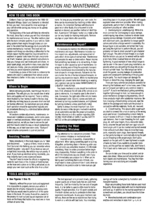 2
2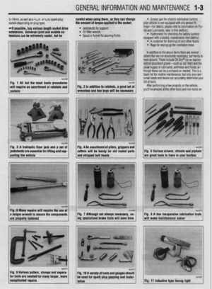 3
3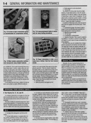 4
4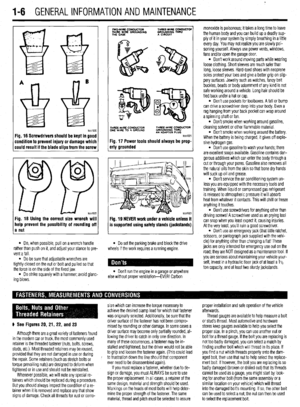 5
5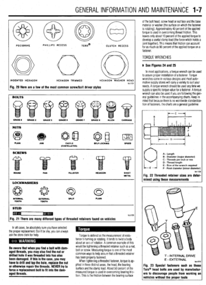 6
6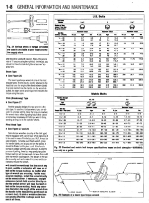 7
7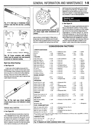 8
8 9
9 10
10 11
11 12
12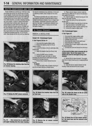 13
13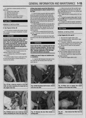 14
14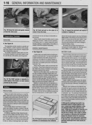 15
15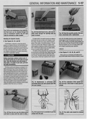 16
16 17
17 18
18 19
19 20
20 21
21 22
22 23
23 24
24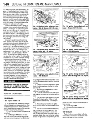 25
25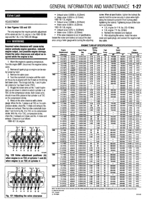 26
26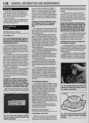 27
27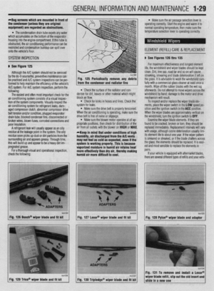 28
28 29
29 30
30 31
31 32
32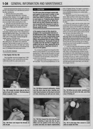 33
33 34
34 35
35 36
36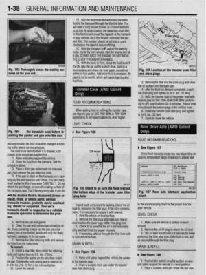 37
37 38
38 39
39 40
40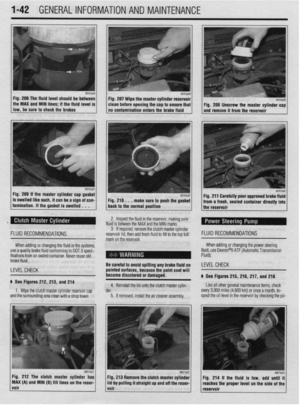 41
41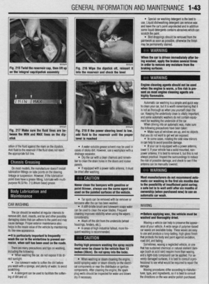 42
42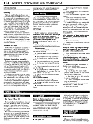 43
43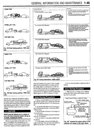 44
44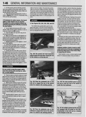 45
45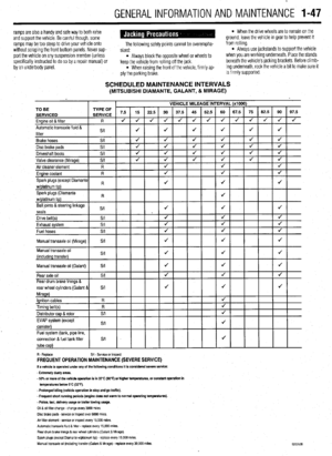 46
46 47
47 48
48 49
49 50
50 51
51 52
52 53
53 54
54 55
55 56
56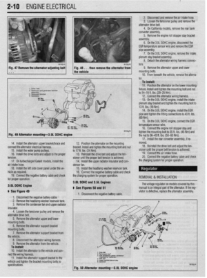 57
57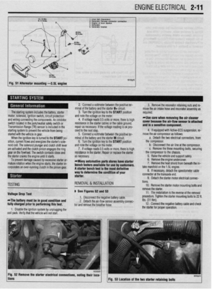 58
58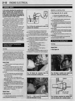 59
59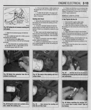 60
60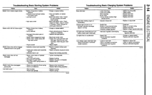 61
61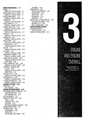 62
62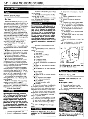 63
63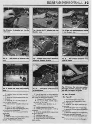 64
64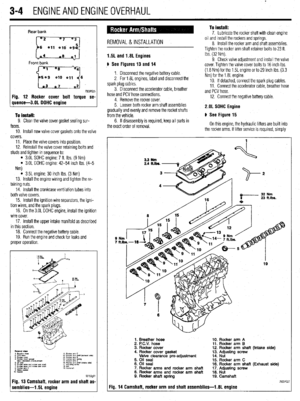 65
65 66
66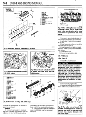 67
67 68
68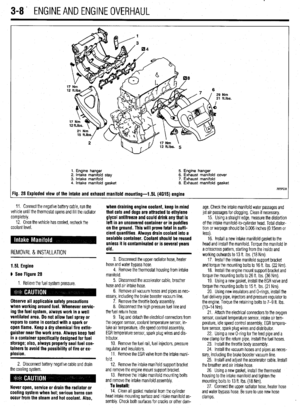 69
69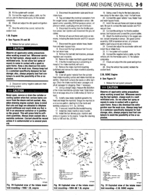 70
70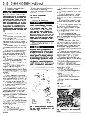 71
71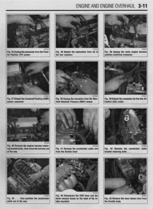 72
72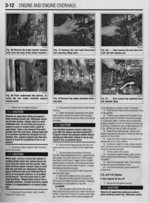 73
73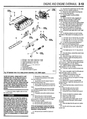 74
74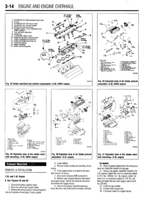 75
75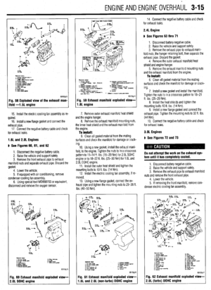 76
76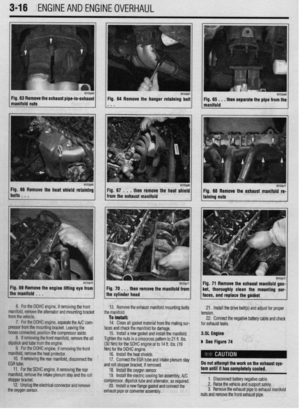 77
77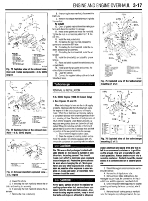 78
78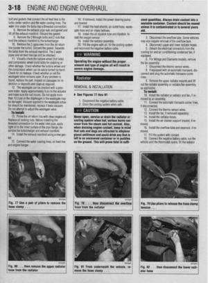 79
79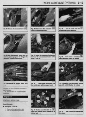 80
80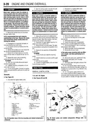 81
81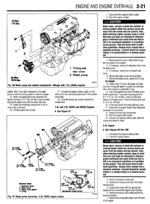 82
82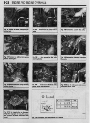 83
83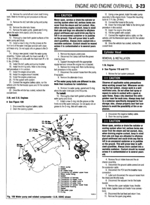 84
84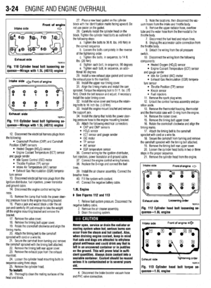 85
85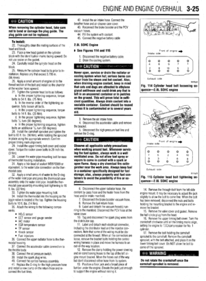 86
86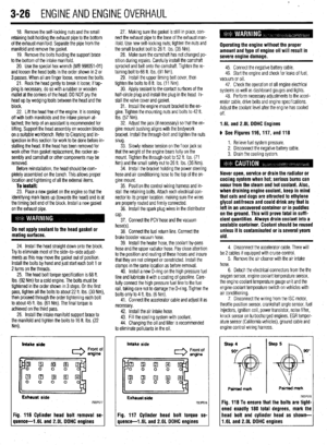 87
87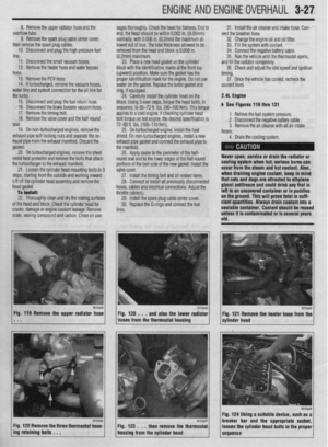 88
88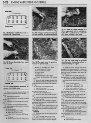 89
89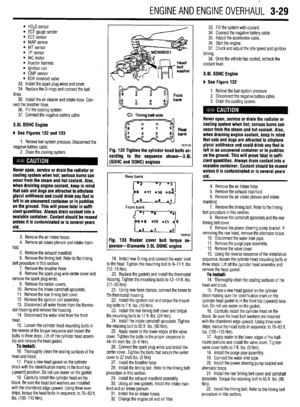 90
90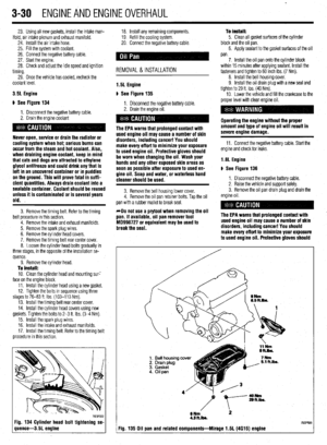 91
91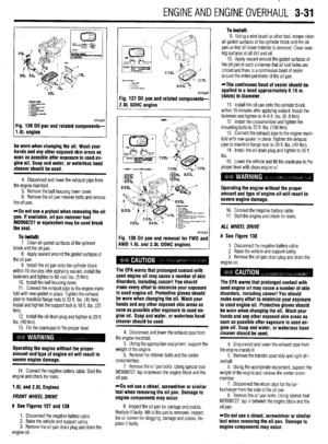 92
92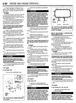 93
93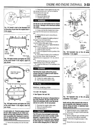 94
94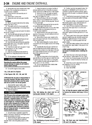 95
95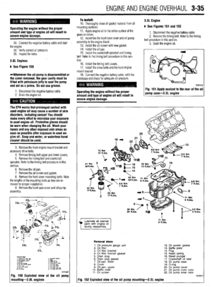 96
96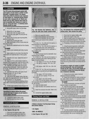 97
97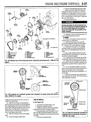 98
98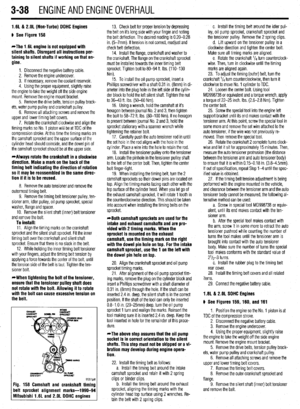 99
99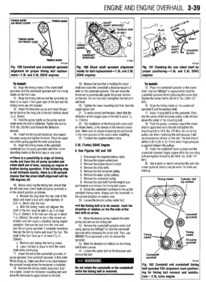 100
100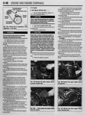 101
101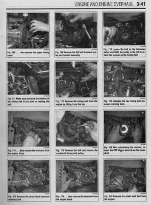 102
102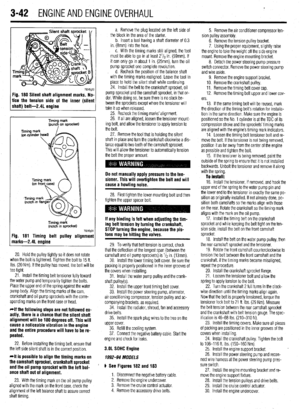 103
103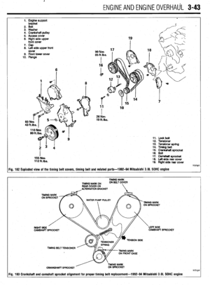 104
104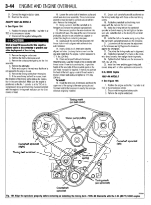 105
105 106
106 107
107 108
108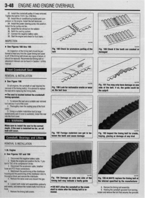 109
109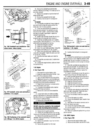 110
110 111
111 112
112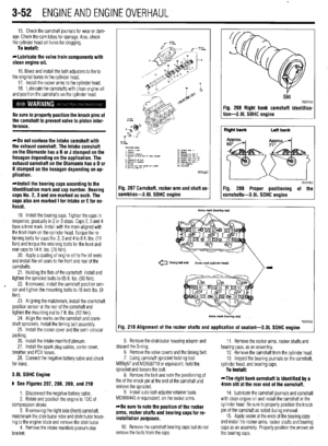 113
113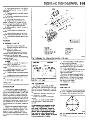 114
114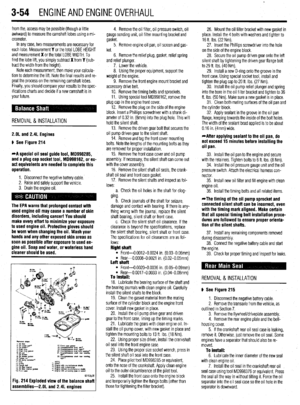 115
115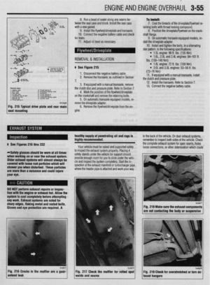 116
116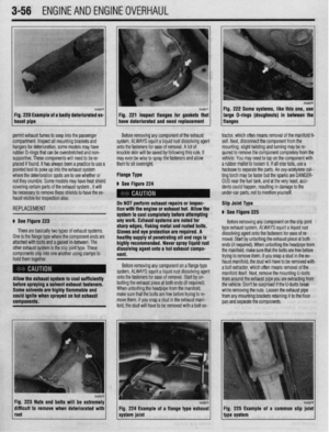 117
117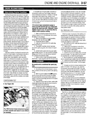 118
118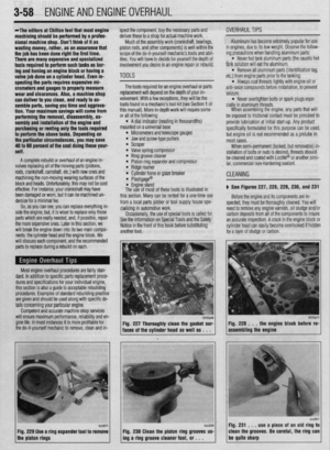 119
119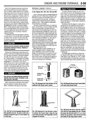 120
120 121
121 122
122 123
123 124
124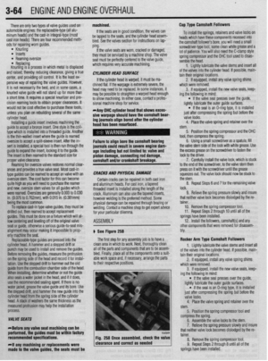 125
125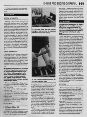 126
126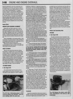 127
127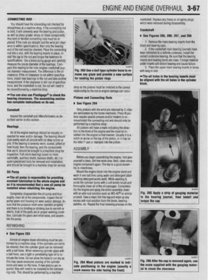 128
128 129
129 130
130 131
131 132
132 133
133 134
134 135
135 136
136 137
137 138
138 139
139 140
140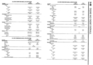 141
141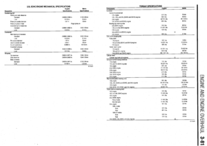 142
142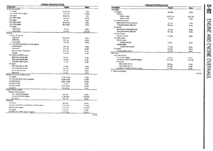 143
143 144
144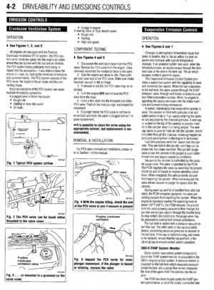 145
145 146
146 147
147 148
148 149
149 150
150 151
151 152
152 153
153 154
154 155
155 156
156 157
157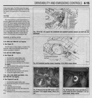 158
158 159
159 160
160 161
161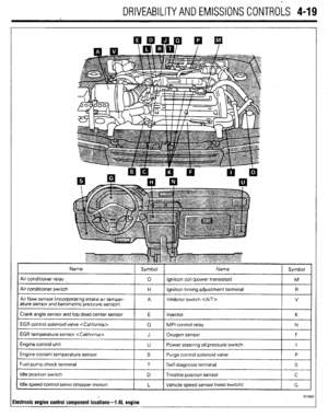 162
162 163
163 164
164 165
165 166
166 167
167 168
168 169
169 170
170 171
171 172
172 173
173 174
174 175
175 176
176 177
177 178
178 179
179 180
180 181
181 182
182 183
183 184
184 185
185 186
186 187
187 188
188 189
189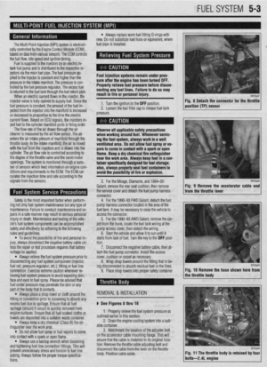 190
190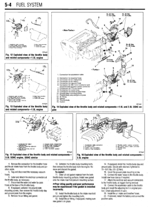 191
191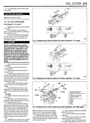 192
192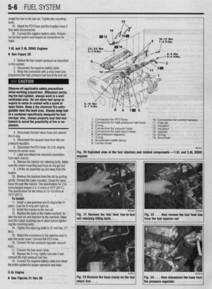 193
193 194
194 195
195 196
196 197
197 198
198 199
199 200
200 201
201 202
202 203
203 204
204 205
205 206
206 207
207 208
208 209
209 210
210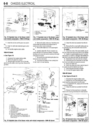 211
211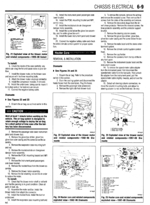 212
212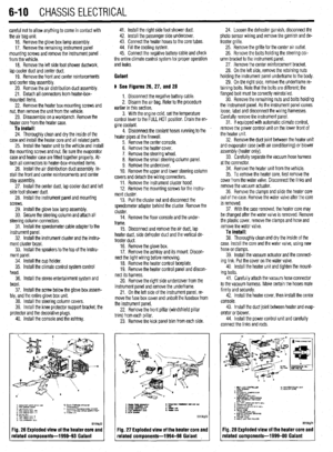 213
213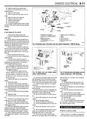 214
214 215
215 216
216 217
217 218
218 219
219 220
220 221
221 222
222 223
223 224
224 225
225 226
226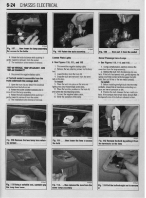 227
227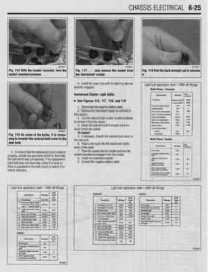 228
228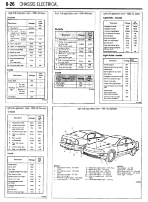 229
229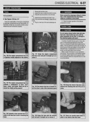 230
230 231
231 232
232 233
233 234
234 235
235 236
236 237
237 238
238 239
239 240
240 241
241 242
242 243
243 244
244 245
245 246
246 247
247 248
248 249
249 250
250 251
251 252
252 253
253 254
254 255
255 256
256 257
257 258
258 259
259 260
260 261
261 262
262 263
263 264
264 265
265 266
266 267
267 268
268 269
269 270
270 271
271 272
272 273
273 274
274 275
275 276
276 277
277 278
278 279
279 280
280 281
281 282
282 283
283 284
284 285
285 286
286 287
287 288
288 289
289 290
290 291
291 292
292 293
293 294
294 295
295 296
296 297
297 298
298 299
299 300
300 301
301 302
302 303
303 304
304 305
305 306
306 307
307 308
308 309
309 310
310 311
311 312
312 313
313 314
314 315
315 316
316 317
317 318
318 319
319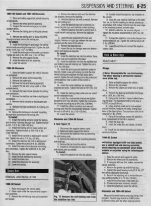 320
320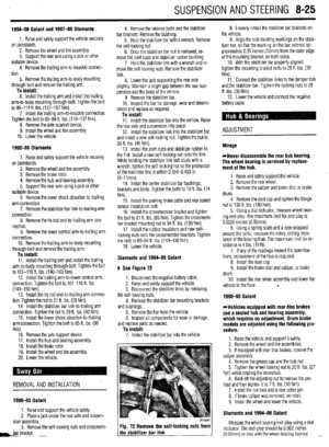 321
321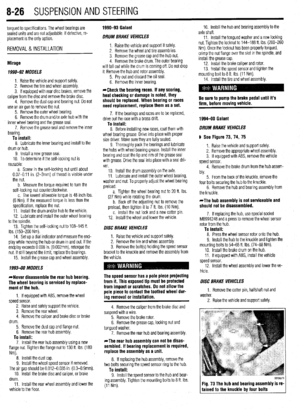 322
322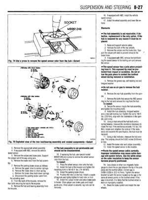 323
323 324
324 325
325 326
326 327
327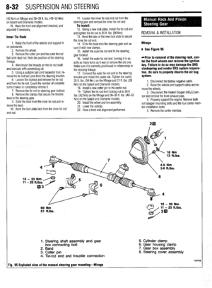 328
328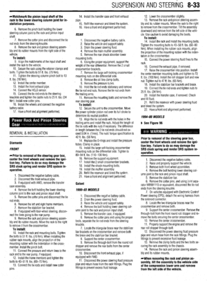 329
329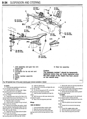 330
330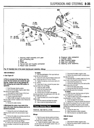 331
331 332
332 333
333 334
334 335
335 336
336 337
337 338
338 339
339 340
340 341
341 342
342 343
343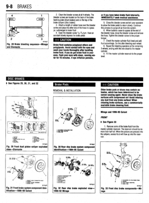 344
344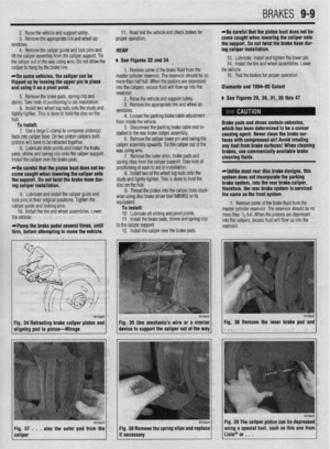 345
345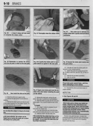 346
346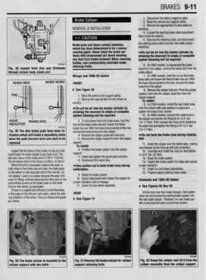 347
347 348
348 349
349 350
350 351
351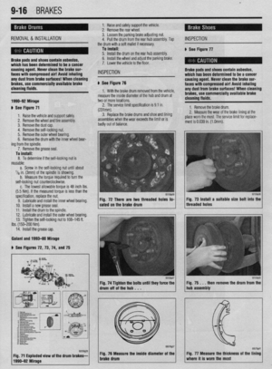 352
352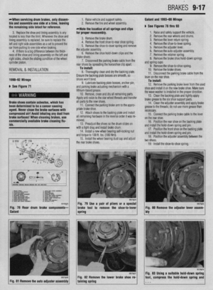 353
353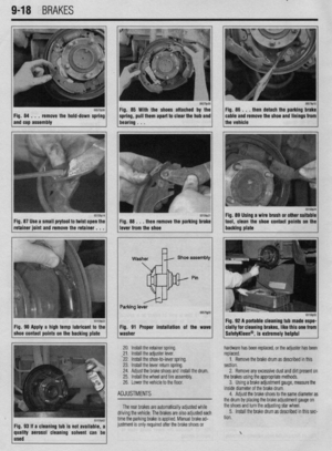 354
354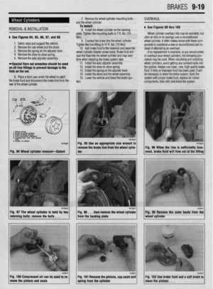 355
355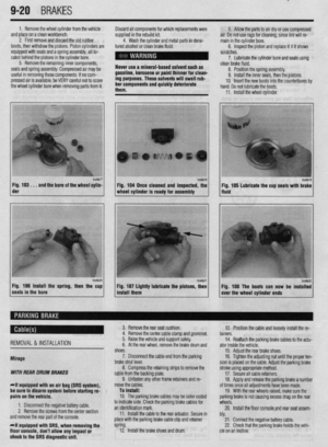 356
356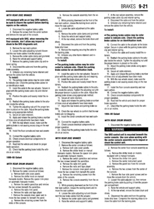 357
357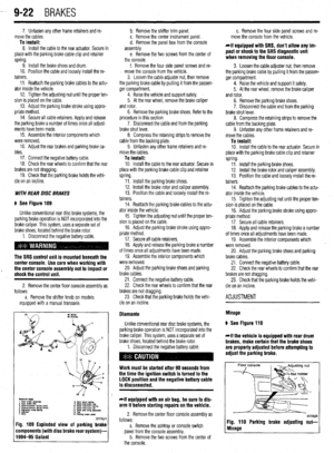 358
358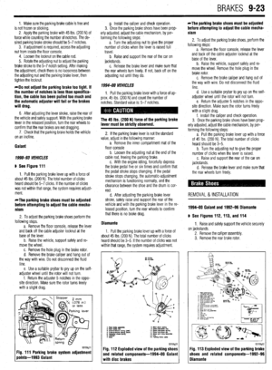 359
359 360
360 361
361 362
362 363
363 364
364 365
365 366
366 367
367 368
368 369
369 370
370 371
371 372
372 373
373 374
374 375
375 376
376 377
377 378
378 379
379 380
380 381
381 382
382 383
383 384
384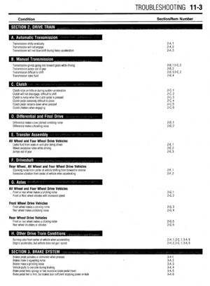 385
385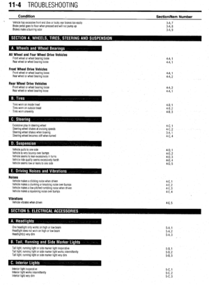 386
386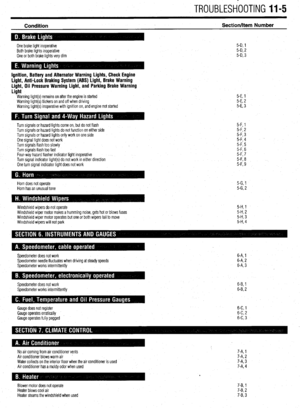 387
387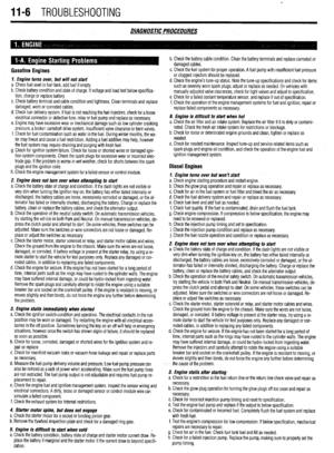 388
388 389
389 390
390 391
391 392
392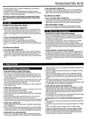 393
393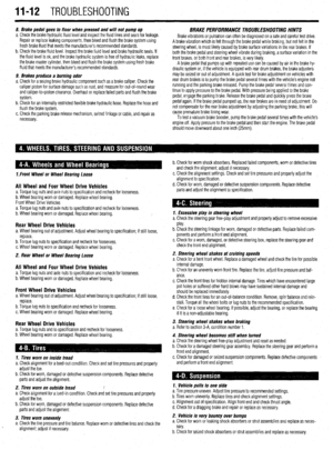 394
394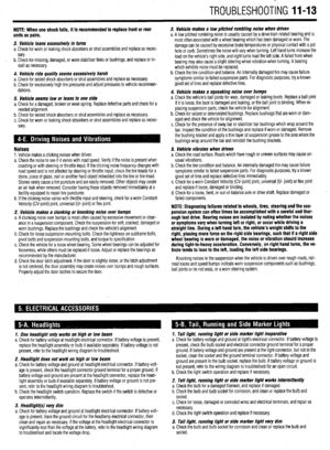 395
395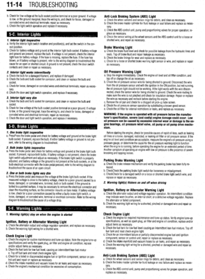 396
396 397
397 398
398 399
399 400
400 401
401 402
402 403
403 404
404 405
405 406
406 407
407