Page 289 of 408

7-10 DRIVETRAIN
The automatic transaxle allows engine torque and
power to be transmitted to the front wheels within a
narrow range of engine operating speeds. It will allow
the engine to turn fast enough to produce plenty of
power and torque at very low speeds, while keeping it
at a sensible rpm at high vehicle speeds (and it does
this job without driver assistance). The transaxle uses
a light fluid as the medium for the transmission of
power. This fluid also works in ths operation of vari-
ous hydraulic control circuits and as a lubricant. Be-
cause the transaxle fluid performs all of these func-
tions, trouble within the unit can easily travel from one
part to another For this reason, and because of the
complexity and unusual operating principles of the
transaxle, a very sound understanding of the basic
principles of operation will simplify troubleshooting
REMOVAL &INSTALLATION
Pan removal, fluid and filter
in Section 1 of this manual changes are covered
REMOVAL &INSTALLATION
1990-97 Mirage and 1990-93 Galant
# See Figure 44
1. Disconnect the negative battery cable.
2. Disconnect the selector cable from the lever
3. Remove the two retaining screws and lift off
the switch.
To install: 4. Mount and position new switch. Do not tighten
the bolts until the switch is adjusted.
5. Connect selector cable and adjust switch.
6. After installation and adjustment make sure the
engine only starts in the
P and N selections. Also check
that the reverse lights operate only in the R selectlon.
1994-00 Galant and 1998-00 Mirage
e See Figure 44
93157pm Fig. 44 Typically, the park/neutral position
switch is located on the top of the transaxle
1. Disconnect the negative battery cable.
2. Remove the nut attaching the shift control ca-
ble from the transaxle manual shaft lever. Position
the control cable out of the way.
3. Place the manual shaft lever in the Neutral
position, remove the nut and the manual shaft lever.
4. Detach the park/neutral switch electrical con-
nector.
5. Remove the park/neutral switch mounting
bolts and remove the switch from the transaxle man-
ual shaft.
To install: 6. Install the park/neutral switch to the transaxle
manual shaft and install the switch mounting bolts
Do not tighten the mounting bolts unh the switch is
adjusted.
7. Install the manual shaft lever to the park/neu-
tral switch with the nut. Make sure that the shaft lever
is in the Neutral position.
8. Adjust the switch in the following manner:
turn the switch body until the hole in the body of the
switch aligns with the hole in the manual shaft lever.
Insert a drill bit or equivalent into the holes. Tighten
the switch mounting bolts to 8 ft. Ibs. (11 Nm).
9. Attach the electrical connector.
10. Install the control cable to the manual shaft
lever with the nut. Adjust the cable so that there is no
slack in the cable and that the selector lever moves
smoothly
11. Reconnect the negative battery cable Check
for proper starting and proper reverse light operatron.
Diamante
ti See Figure 44
1. Disconnect the negative battery cable.
Wait at least 90 seconds after the negative
battery cable is disconnected to prevent pos-
sible deployment of the air bag.
2. Disconnect the selector cable from the lever.
3. Remove the two retaining screws and lift off
the switch.
To install: 4. Install the lever, tighten the bolts only hand
tight.
5. Rotate switch body so the manual control lever
0.20 inch (5mm) hole and the switch body 0.20 inch
(5mm) holes are aligned.
6. Tighten the mounting bolts to 7-8 ft. Ibs.
(10-12 Nm).
7. Connect the selector cable to the lever.
8. Connect the negative battery cable.
9. After installahon and adjustment make sure the
engine only starts in the
P and N selections. Also
check that the reverse lights operate only in the R se- lection.
ADJUSTMENT
1990-97 Mirage and 1990-93 Galant
1. Disconnect the negative battery cable and lo-
cate the neutral safety switch on the top of the
transaxle.
*Apply parking brake and chock wheels be-
fore placing transaxle into the N position
2. At the transmission, loosen the shift cable ad-
justment nut. Inside the vehicle place the gearshift
selector lever in N
3. Place the manual shift control lever in N.
4. Loosen neutral safety switch mounhng screws
and rotate switch body so the manual control lever
0.20 in. (5mm) hole and the switch body 0.20 in.
(5mm) holes are aligned.
5. Tighten switch body mounting bolts to 7-8 ft.
Ibs. (lo-12 Nm).
6. At the shift cable adjusting nut, gently pull ca-
ble to remove any slack. Tighten locknut to 8 ft. Ibs.
(12 Nm)
7. Verify that the switch lever moves to positions
corresponding to each position of the selector lever.
Connect the negative battery terminal.
8. Make sure the engine only starts in the
P and
N positions. Also make sure the reverse lights oper-
ate only in
R selection.
REMOVAL&INSTALLATION
Diamante
) See Figures 45, 46, 47, and 48
1. Properly disarm the SRS system (air bag).
Refer to Section 6.
2. Raise and safely support the vehicle.
3. Remove the front wheels.
4. Remove the engine side cover and undercov-
ers.
5. Drain the transaxle assembly into a suitable
container.
6. If equipped, remove the front catalytic con-
verter.
7. Remove the exhaust pipe, main muffler and
catalytic converter.
8. Disconnect the tie rod end and ball joint from
the steering knuckle.
9. Unbolt the support bearing for the left side
halfshaft.
10. Remove the halfshafts by inserting a prybar
between the transaxle case and the driveshaft and
prying the shaft from the transaxle.
11. Remove the air cleaner assembly and adjoin-
ing duct work.
12. Detach the engine harness connection.
13. If the vehicle is equipped with Active Elec-
tronlc Controlled Suspension (Active-ECS), remove
the compressor assembly from the transaxle and sus-
pend with wire. Do not allow the compressor to hang
from the air hose.
14. If equipped, remove the roll stopper stay
bracket.
15. Disconnect the speedometer cable from the
transaxle.
16. Remove the clip that secures the shifter and
disconnect the shifter control cable from the
transaxle.
17. Disconnect and plug the oil cooler hoses
from the transaxle.
18. Detach the following:
Page 290 of 408

DRIVETRAIN 7-11
Fig. 45 location of 4-wheel steering oil
l Park/neutral switch electrical harness l Kickdown servo switch l Pulse generator l Oil temperature sensor electrical harness l Shift control solenoid valve harness.
19. Support the transaxle and remove the
transaxle mounting bracket.
20. Remove the three upper transaxle-to-engine
mounting bolts.
21. For vehicles with 4WS, remove the heat
shield for the 4WS oil pump and remove the pump.
Do not allow the pump to hang from the oil hoses.
22. For vehicles equipped with Active-ECS, dis-
connect the height sensor rod from the lower control
arm.
23. Remove the bolt that secures the Heated Oxy-
gen (HOaS) sensor harness to the right side cross-
member.
’ 24. Remove the starter assembly.
25. Remove the mounting brackets for access to
the bell housing cover,
26. Remove the bell housing/oil pan covers as-
sembly. 27. Remove the bolts holding the flexplate to the
torque converter.
28. Remove the lower transaxle to engine bolts
and remove the transaxle assembly.
To install: 29. Install the transaxle assembly to the engine
block, install the mounting bolts and tighten to 54 ft.
tbs. (75 Nm).
30. Install the bolts that secure the torque con-
verter to the driveplate. Tighten the bolts to 34-38 ft.
Ibs (4653 Nm).
31. Install the bell housing/oil pan covers.
32. Install the transaxle stay brackets that were
removed for access to the bell housing cover.
33. Install the starter assembly and connect the
wiring.
34. Install the bolt that secures the HO& sensor
harness to the right side crossmember and tighten
the bolt to 7-9 ft. Ibs. (X-12 Nm).
35. For vehicles equipped with Active-ECS, con-
nect the height sensor rod from the lower control’
arm. Check the height sensor rod for a length (A) of
10.59-10.63 in. (269-270mm)
36. If removed, install the 4WS oil pump and
tighten the mounting bolts to 17 ft. Ibs. (24 Nm).
37. If removed, install the 4WS oil pump heat
shield and tighten the mounting bolts to 17 ft. Ibs.
(24 Nm).
38. Install the three upper transaxle-to-engine
mounting bolts. Tighten the mounting bolts to 54 ft.
Ibs. (75 Nm).
*One of the upper bolts has a grounding
strap to secure under the bolt.
39. Install and connect the transaxle mounting
bracket. Tighten the mounting nut and bolts to 51 ft.
Ibs. (70 Nm).
40. Connect the shift control solenoid valve har-
ness
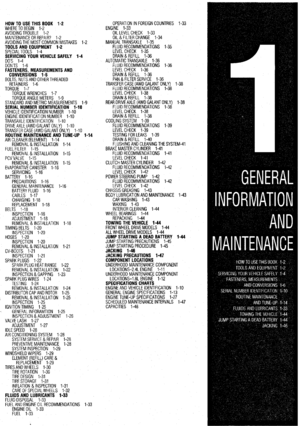
Removal steps 1. Transaxle control cable connection
2. Transaxle 011 cooler hoses connection
3. PNP swrtch connector
4. FvT control solenoid valve connector
5. Input shaft speed sensor connector
6. Output shaft speed sensor connector
7. Vehicle speed sensor connector
6. Spht pin
9. Connection of the tie rod end
10. Drwe shaft nut 11. Connectton for the lower arm ball
jomt
12. Drwe shaft and inner shaft assembly
(RH) and the drwe shaft (LH)
Caution
Mounting locations marked by
l should be
provisionally tightened, and then fully tightened
when the body is supporting the full weight of the
engine.
7923PG84
:io. 46 Transaxie removal (1 of 2)-Diamante with F4A51 transaxie
41. Connect the kickdown servo switch, pulse
generator and oil temperature sensor electrical har-
ness
42. Connect the park/neutral switch electrical
harness.
43. Using new hose clamps, install the oil cooler
hoses to the transaxle.
44. Install shifter control cable to the transaxle
and secure the cable with clip.
45. Connect the speedometer cable to the
transaxle.
46. If removed, install the roll stopper stay
bracket and tighten the one through nut and bolt to
36-43 ft. Ibs. (50-60 Nm). Tighten the two mounting
bolts to 16 ft. Ibs. (22 Nm).
47. If removed, install the Active-ECS compres-
sor assembly. Tighten the mounting bolts to 48 inch
Ibs. (5 Nm) and connect the electrical harness.
48. Attach the engine harness connection.
49. Install the air cleaner assembly and adjoining
duct work.
50. Using new circlips, install the halfshafts and
seat halfshafts into the transaxle. Install the bolt that
secure the left side support bearing and tighten the
bolts to 33 ft. Ibs. (45 Nm).
51. Connect the ball joint and tie rod end to the
steering knuckle. Using new nuts, tighten the ball
joint castle nut to 43-52 ft. Ibs. (60-72 Nm) and
tighten the tie rod castle nut to 22 ft. ibs. (30 Nm). in-
stall new cotter pins.
52. Using new gaskets, install the exhaust sys-
tem.
53. If removed, install front catalytic converter.
54. Install the engine undercovers.
55. Connect the negative battery cable.
56. Fill the transaxle to the correct level.
57. Start the engine and check for leaks.
Gaiant
1999-1993 MODELS
1. On vehicles equipped with auto-cruise, re-
move the control actuator and bracket.
2. If equipped with an active ECS, disconnect
the air compressor.
3. Drain the transaxle fluid into a suitable con-
tainer.
4. Remove the air cleaner assembly, intercooler
and air hose, as required.
5. Mark the shift cable. Remove the adjusting
nut and disconnect the shift cable.
6. Tag and detach the electrical connectors for
the solenoid, neutral safety switch (inhibitor switch),
the pulse generator kickdown servo switch and oil
temperature sensor.
7. Disconnect the speedometer cable and oil
cooler lines.
8. Disconnect the wires to the starter motor and
remove the starter.
9. Remove the upper transaxle to engine bolts.
10. Support the transaxle and remove the
transaxle mounting bracket.
11. Raise the vehicle and support safely. Remove
the sheet metal under guard
12. Remove the tie rod ends and the bail joints
from the steering knuckle.
13. Remove the halfshafts by inserting a prybar
between the transaxle case and the driveshaft and
prying the shaft from the transaxle. Do not pull on the
driveshaft. Doing so damages the inboard joint. Use
Page 291 of 408

.
7-12 DRIVETRAIN
26-33Nm
19 - 24 itlbs.
45 - 52 Nm
69 Nm
51 ftlbs.
66 Nm
65 ftlbs.
52 Nm
36 fl.lbs.
:ig.
the prybar. Do not insert the prybar so far the oil seal
in the case is damaged. Tie the halfshafts aside.
14. On AWD vehicles, disconnect the exhaust
pipe and remove the transfer case.
15. Remove the lower bellhousing cover and re-
move the special bolts holding the flexplate to the
torque converter. To remove, turn the engine crank-
shaft with a box wrench and bring the bolts into a po-
sition appropriate for removal, one at a time. After re-
moving the bolts, push the torque converter toward
the transaxle so it doesn’t stay on the engine allowing
oil to pour out the converter hub or cause damage to
the converter,
16. Remove the lower transaxle to engine bolts
and remove the transaxle assembly. To install: 17. After the torque converter has been mounted
on the transaxle, install the transaxle assembly on the
engine. Tighten the driveplate bolts to 34-38 ft. Ibs.
(4653 Nm). Tighten the transaxle-to-engine bolts to
35 ft. Ibs. (48 Nm). Install the bellhousing cover.
18. On AWD vehicles, install the transfer case
and frame pieces. Connect the exhaust pipe using a
new gasket.
19. Replace the circlips and install the halfshafts
to the transaxle.
20. Install the tie rods and ball joint to the steer-
ing arm.
21. Install the transaxle mounting bracket.
22. install the under guard.
23. Install the starter.
24. Connect the speedometer cable and oil cooler
lines.
25 Connect the solenoid, neutral safety switch
(inhibitor switch), the pulse generator kickdown
servo switch and oil temperature sensor.
26. Install the shift control cable.
27. Install the air hose, intercooler and air cleaner
assembly.
If equipped with an active ECS, connect the
mante with a F4A33 automatic transaxle
30 Refill with Dexron II, Mopar ATF Plus type
7176, Mitsubishi Plus ATF or equivalent, automatic
transaxle fluid. If vehicle is AWD check and fill the
transfer case.
31. Start the engine and allow to idle for 2 min-
utes. Apply parkrng brake and move selector through
each gear posrtion, ending in N. Recheck fluid level
and add if necessary. Fluid level should be between
the marks in the HOT range.
1994-90 MODELS
1. Disconnect the negative battery cable.
2. Remove the air cleaner and intake hoses.
3. Drain the transaxle into a suitable waste con-
tainer.
4. Remove the nut securing the shifter lever to
the transaxle. Remove the cable retaining clip and re-
move the cable from the transaxle.
5. Remove the shifter cable mounting bracket,
6. Tag and detach the electrical connectors for
the speedometer, solenoid, neutral safety switch (in-
hibitor switch), the pulse generator, kickdown servo
switch, and the oil temperature sensor.
7. Tag and disconnect the oil cooler lines at the
transaxle.
8. Remove the bolt securing the fluid dipstick
tube to the transaxle. Remove the dipstrck and tube
from the transaxle.
9. Remove the starter motor and position it
aside.
10. Using special tool MZ203827 or equivalent,
support the engine assembly.
11. Remove the rear roll stopper mounting
bracket.
12. Remove the transaxle mount bracket.
13. Remove the upper transaxle mounting bolts.
14. Raise and safely support the vehicle.
15. Remove the front wheel assemblies.
16. Remove the right hand undercover.
17. Remove and discard the cotter pin, then dis-
connect the tie rod end from the steering knuckle,
18. Disconnect the stabilizer bar link from the
damper fork.
19. Disconnect the damper fork from the lateral
lower control arm.
20. Disconnect the lateral lower arm, and the
compression arm lower ball joints from the steering
knuckle.
21. Pry the halfshafts from the transaxle, and se-
cure aside.
22. Remove the cover from the transaxle bell-
housing.
23. Remove the engine front roll stopper
through-bolt.
24. Remove the crossmember and the triangular
right hand stay.
25. Remove the bolts holding the flexplate to the
torque converter with a box wrench Rotate the engine
to bring the bolts into a position appropriate for re-
moval, one at a time. After removing the bolts, push
the torque converter toward the transaxle. This will
prevent the converter from remaining intact with the
engine, possibly damaging the converter,
26. Support the transaxle, using a transmission
jack, and remove the transaxle lower coupling bolt.
*The coupling bolt threads from the engine
side, into the transaxle, and is located just
above the halfshafl opening.
Page 292 of 408

DRIVETRAIN 7-13
27. Shde the transaxle rearward and carefully
lower it from the vehicle.
To install: 28. After the torque converter has been mounted
on the transaxle, install the transaxle assembly to the
engine. Install the mounting bolts and tighten to 35
ft. Ibs. (48 Nm).
29. Install the transaxle lower coupling bolt and
tighten to 21-25 ft Ibs. (29-34 Nm).
30. Connect the torque converter to the flexplate
and tighten the bolts to 33-38 ft. Ibs. (45-52 Nm).
31. Install the cover to the transaxle bellhous-
ing and tighten the mounting bolts to 7 ft. Ibs. (9
Nm).
32 Install the crossmember and tighten the front
mounting bolts to 65 ft. Ibs (88 Nm) and the rear
bolt to 54 ft. Ibs. (73 Nm) Install the front engine roll
stopper through-bolt and lightly tighten. Once the full
weight of the engine is on the mounts, tighten the ’
bolt to 42 ft. Ibs. (57 Nm),
33. Install the triangular stay bracket and tighten
the mounting bolts to 65 ft. Ibs. (88 Nm).
34. Install the halfshafts, using new circlips on
the axle ends.
When installing the axleshaft, keep the in-
board joint straight in relation to the axle, so
as not to damage the oil seal lip of the
transaxle with the serrated part of the half-
shaft.
35. Connect the tie rod and ball joints to the
steering knuckle. Tighten the ball joint self-locking
nuts to 48 ft. Ibs. (65 Nm). Tighten the tie rod end nut
to 21 ft. Ibs. (28 Nm) and secure with a new cotter
pin.
36. Connect the damper fork to the lower control
arm and tighten the through-bolt to 65 ft Ibs. (88
Nm).
37. Connect the stabilizer link to the damper fork,
and tighten the self-locking nut to 29 ft. Ibs. (39 Nm).
38. Install the undercover.
39. Install the wheels and carefully lower the ve-
hicle
40. Install the transaxle mount bracket to the
transaxle, and tighten the mounting nuts to 32 ft. Ibs.
(43 Nm).
41. Install the rear roll stopper mounting bracket.
42. Remove the engine support. Tighten the
transaxle mount through-bolt to 51 ft. Ibs. (69 Nm)
and tighten the front engine roll stopper through-bolt.
43. Install the upper transaxle mounting bolts
and tighten to 35 fl. Ibs. (48 Nm).
44. Install the starter motor.
45. Install the dipstick tube and the dipstick
46. Install the shifter cable mounting bracket.
47. Connect the shifter lever and tighten the re-
taining nut to 14 ft. Ibs. (19 Nm).
48. Connect the oil cooler lines and secure with
clamps.
49. Attach the electrical connectors for the
speedometer, solenoid, neutral safety switch (in-,
hibitor switch), the pulse generator, kickdown servo
switch and oil temperature sensor.
50. Install the air cleaner and the air intake hose.
51. Connect the negative battery cable.
52. Make sure the vehicle is level, and refill the
transaxle. Start the engine and allow to idle for 2 minutes. Apply parking brake and move selector
through each gear position, ending in N. Recheck
fluid level and add if necessary. Fluid level should be
between the marks in the HOT range.
53. Check the transaxle for proper operation.
Make sure the reverse lights come on when in re-
verse and the engine starts only in
P or N.
Mirage
*If the vehicle is going to be rolled on its
wheels while the halfshafts are out of the ve-
hicle, obtain two outer CV-joints or proper
equivalent tools and install to the hubs. If the
vehicle is rolled without the proper torque
applied to the front wheel bearings, the bear-
ings will no longer be usable.
1. Disconnect the negative battery cable then
the positive battery cable.
2. Remove the battery and battery tray.
3. Remove the air hose and air cleaner assem-
bly.
4. Raise the vehicle and support safely.
5. Remove the under guard pan.
6. Drain the transaxle oil into a suitable con-
tainer.
7. If equipped with 1.6L engine, remove the ten-
sion rod.
8. Disconnect the control cable and cooler
lines.
9. On 3-speed transaxles, disconnect the throt-
tle control cable.
10. On 4-speed transaxles, perform the following:
a. Detach the shift control solenoid valve
connector.
b. Disconnect the inhibitor switch and kick-
down servo switch.
c. Disconnect the pulse generator and oil
temperature sensor.
11. Disconnect the speedometer cable and re-
move the starter.
12. Remove the transaxle mounting bolts and
bracket.
13. Disconnect the stabilizer bar from the lower
control arm.
14. Disconnect the steering tie rod end and the
ball joint from the steering arm.
15. Remove the halfshafts at the inboard side
from the transaxle. Tie the joint assembly aside.
*It is not necessary to disconnect the half-
shafts from the wheel hubs.
16. Support the engine and remove the center
member.
17. Remove the bellhousing cover and remove
the driveplate bolts.
18 Remove the transaxle assembly lower con-
necting bolt, located just over the halfshaft opening.
19. Properly support the transaxle assembly, then
lower it, moving it to the right for clearance.
To install: 20. After the torque converter has been mounted
on the transaxle, install the transaxle assembly on the
engine. Install the mounting bolts and tighten to
31-40 ft. Ibs. (43-55 Nm) on 1990-92 models and
35 ft. Ibs. (48 Nm) on 1993-00 models.
21. Tighten the driveplate bolts to 33-38 ft. Ibs.
(46-53 Nm). Install the bellhousing cover.
22. Install the center member. 23. Replace the circlips and install the halfshafts
to the transaxle.
24. Install the tie rods, ball joints and stabilizer
links to the steering arm
25. Install the transaxle mounting bracket and
bolts.
26. Install the starter.
27. Connect the speedometer cable.
28. Connect the inhibitor switch, kickdown servo
switch, the pulse generator and oil temperature sen-
sor, if disconnected.
29. Connect the shift control solenoid valve con-
nector.
30. Connect the control cables and oil cooler
lines.
31. Install the tension rod, if removed.
32. Install the air cleaner assembly.
33. Install the battery tray and battery.
34. Connect the positive then the negative termi-
nal.
35. Refill with Dexron@ II, Mopar ATF Plus type
7176 or equivalent, automatic transaxle fluid.
36. Start the engine and allow to idle for two min-
utes. Apply parking brake and move selector through
each gear position, ending in N. Recheck fluid level
and add if necessary. Fluid level should be between
the marks in the HOT range.
ADJUSTMENTS
Shifter Control Cable Adjustment
1. The shifter cable adjustment is done at the
neutral safety switch (inhibitor switch). Locate the
switch on the transaxle and note the alignment holes
in the arm and the body of the switch. Place the se-
lector lever in N. Place the manual lever of the
transaxle in the neutral position.
2. Check alignment of the hole in the manual
control lever to the hole in the inhibitor switch body.
If the holes do not align, adjustment is required.
3. To adjust, loosen the nut on the cable end and
pull the cable end by hand until the alignment holes
match. Tighten the nut. Check that the transaxle
shifts and conforms to the positions of the selector
lever.
Throttle Valve Cable
The throttle valve adjustment applies only to the
1990-96 Mirage.
1. Place selector lever and manual control lever
in N position.
2. Loosen adjusting nut. While lightly pulling on
control cable tighten mounting nut to 7-10 ft. Ibs.
(X-14 Nm).
3. When adjustment is complete, be sure selector
lever is still in the N position. Verify all functions
correspond to the position indicated on the selector
lever.
The halfshaft removal and installation and over-
haul are the same as a manual transaxle Please refer
to Manual Transaxle in this Section
Page 293 of 408

7-14 DRIVETRAIN
The only model covered by this manual equipped
with a transfer case is the 1990-93 AWD Galant. assembly. Place a drain pan under the rear of the
transfer assembly to catch any fluid that leaks out.
3. Usinq a flat-bladed prying tool, carefully re-
REMOVAL &INSTALLATION
move the ofi seal from the transfer dust seal guard
To install: 4. Using proper size seal driver tool, install the
seal into the dust seal quard and the transfer assem-
blv.
# See Figures 49 and 50
1. Raise and support the vehicle safely.
2. Remove the propeller shaft from the transfer ‘5. Install the rear propeller shaft.
6. Carefully lower the vehicle and inspect the
transfer assembly fluid level.
a9577g50 1 Fig. 49 Exploded view of the transfer case
1 extension housing and related components a9577g51 Fig. 50 Install the oil seal using the proper
sized driver and a hammer REMOVAL &INSTALLATION
1. Disconnect the battery negative cable.
2. Raise the vehicle and support safely. Drain the
transfer oil.
3. Disconnect the front exhaust pipe.
4. Unbolt the transfer case assembly and remove
by sliding it off the rear driveshaft. Be careful not to
damage the oil seal in the transfer case output hous-
ing. Do not let the rear driveshaft hang; suspend it
from a frame piece. Cover the opening in the
transaxle and transfer case to keep oil from dripping
and to keep dirt out.
5. Lubricate the driveshaft sleeve yoke and oil
seal lipan the transfer extension housing. Install the
transfer case assembly to the transaxle. Use care
when installing the rear driveshaft to the transfer case
output shaft.
6. Tighten the transfer case to transaxle bolts to
40-43 ft. Ibs. (55-60 Nm) with manual transaxle;
43-58 ft. Ibs. (60-80 Nm) with automatic transaxle.
7. Install the exhaust pipe using a new gasket. In-
stall removed bumper components.
8. Refill the transfer case and check oil levels in
transaxle and transfer case.
The only model covered by this manual equipped
with a driveshaft is the 1990-93 AWD Galant.
REMOVAL &INSTALLATION
) See Figures 51 and 52
1. Disconnect the negative battery cable. Raise
the vehicle and support safely.
2. The rear driveshaft is a 3-piece unit, with a
front, center and rear propeller shaft. Remove the
nuts and msulators from the center support bearing.
Work carefully. There will be a number of spacers
which will differ from vehicle to vehicle. Check the
number of spacers and write down their locations for
reference during reassembly.
3. Matchmark the rear differential companion
flange and the rear driveshaft flange yoke. Remove
the companion shaft bolts and remove the driveshaft,
keeping it as straight as possible so as to ensure that
the boot is not damaged or pinched. Use care to keep
from damaging the oil seal in the output housing of
the transfer case.
*Damage to the boot can be avoided and
work will be easier if a piece of cloth or simi-
lar material is inserted in the boot.
4. Do not lower the rear of the vehicle or oil will
flow from the transfer case. Cover the opening to
keep dirt out.
To install: 5. Position the driveshaft in the vehicle, making
sure to align the matchmarks at the rear yoke.
6. Install the bolts at the rear differential flange
and tighten to 22-25 ft. Ibs. (30-35 Nm). 7. Install the center support bearing with all spac- 2 Force out the bearing journals from the yoke
ers in place. Tighten the retaining nuts to 22-25 ft. using a large C-clamp. Install a collar on the fixed
Ibs. (3C-35 Nm). side of the C-clamp. Press the journal bearing into
8. Check the fluid levels in the transfer case and the collar by applying pressure with the C-clamp, on
rear differential case. the opposite side.
U-JOINTREPLACEMENT
1. Make mating marks on the yoke and the uni-
versa1 joint that is to be disassembled. Remove the
snaprings from the yoke with snapring pliers. 3. Pull the journal bearing from the yoke.
rlf the journal bearing is hard to remove,
strike the yoke with a plastic hammer.
4. Press the journal shaft using C-clamp or simi-
lar tool, to remove the remaining bearings.
Fiu. 51 Exploded view of the proueller shafl mounting
Page 294 of 408

DRIVETRAiN 7-15
MATING MARKS
/
89577Q5E Fig. 52 Apply mating marks on the flange
yoke and differential companion flange
5. Once all bearings are removed, remove the
journal.
To install:
6. Apply multi-purpose grease to the shafts,
grease sumps, dust seal lips and needle roller bear-
ings of the replacement U-joint Do not apply exces-
sive grease Otherwse, faulty fitting of bearing caps
and errors in selection of snaprings may result.
7. Press fit the journal bearings to the yoke using
a C-clamp as follows:
a. Install a solid base onto the bottom of the
C-clamp.
b. Insert both bearings into the yoke. Hold
and press fit them by tightening the C-clamp.
c. Install snaprings of the same thickness
onto both sides of each yoke.
d. Press the bearing and journal into one side, using a brass bar with diameter of 0.59 in.
(15mm).
8. Measure the clearance between the snapring
and the groove wall of the yoke with a feeler gauge. If
the clearance exceeds 0.0008-0.0024 in.
(0.02-O.O6mm), the snap rings should be replaced.
DRIVESHAFT BALANCING
Driveshaft balancing is a process best left for a
professional wrth the proper equipment. Makeshift
methods using hose clamps or similar devices can
work, but the process of correcting the imbalance in
this manner is very tough and extremely time con-
suming.
Many machine shops can balance driveshafts;
some parts stores and jobbers can also balance dri-
veshafts using outside contractors.
REMOVAL&INSTALLATION
1. Place matmg marks on the companron flange
and the Lobro joint assembly
2. Remove the Lobro joint installation bolts.
Separate the Lobro joint from the companion flange.
3. Place mating marks on the center yoke and
center propeller shaft, and the companion flange and
the rear propeller shaft.
4. Remove the self-locking nuts. Remove the
center yoke and companion flange. 5. Place mating marks on the center bearing as-
sembly front bracket and the center propeller shaft,
and the center bearing assembly rear bracket and the
rear propeller shaft. Remove the center bearing
bracket.
*The mounting rubber can not be removed
from the center bearing bracket.
6. Pull out the front and rear center bearings
with a commercially available puller
To install:
7. Apply multi-purpose grease to the center
bearing front and rear grease grooves and to the dust
seal lip Be sure to fit the bearing into the rubber
mount groove on the center bearing bracket.
*Face the bearing dust seal to the side of
the center bearing bracket mating mark.
8. Assemble the center bearing to the center
propeller shaft and rear propeller shaft. Face the side
onto which the center bearing bracket mating marks
IS placed and the dust seal is installed toward the
side of the center propeller shaft and rear propeller
shaft.
9 Apply a thin and even coat of the grease, en-
closed with the repair kit, to the rubber packing on
the companion flange. Align the mating marks on the
center propeller shaft and the companion flange, then
press fit the center bearing with self-locking nuts.
10 Install the Lobro joint assembly installation
bolts. Secure the companron flange and Lobro joint
assembly with the installation bolts Check for grease
leakage from the Lobro joint boot and companion
flange installabon parts.
The only model covered by this manual equipped
with a rear axle differential is the 1990-93 AWD
Galant.
REMOVAL &INSTALLATION
# See Figures 53 and 54
1. Disconnect the negative battery cable. Raise
the vehicle and support safely.
2. Remove the bolts that attach the rear halfshaft
to the comoanion flanae.
3. Use’a prybar topry the inner shaft out of the
I Fig. 53 Rear driveshaft mounting
89577g5
differential case. Don’t insert the prybar too far or the
seal could be damaged.
4 Remove the rear driveshaft from the vehicle.
5. If necessary, carefully pry the oil seal from the
rear differential using a flat tipped prying tool.
To install:
6. Install a new oil seal into the rear differential
housing using proper size driver.
7. Replace the circlip and install the rear drive-
shaft to the differential case. Make sure it snaps in
place.
8. Install the companion flange bolts and tighten
to 40-47 ft. Ibs. (55-65 Nm).
9. Check the fluid level in the rear differential.
69577958 Fig. 54 Remove the driveshaft from the dif-
ferential carrier with a prybar
REMOVAL &INSTALLATION
1. Disconnect the negative battery cable.
2. Raise and support the vehicle safely.
3 Remove the tire and wheel assembly from the
vehicle.
4 If equipped with ABS, remove the rear wheel
speed sensor.
*Be cautious to ensure that the tip of the
pole piece on the rear speed sensor does not
come in contact with other parts during re-
moval. Sensor damage could occur.
5. Remove the rear caliper and support assem-
bly out of the way. Remove the brake disc.
6. Remove the driveshaft and companion flange
installation bolts, nuts and washers. Move the end of
shaft slightly to access the self-locking nut.
7. Using axle holding tool MBSbll-01 or
equivalent, secure the rear axle shaft in position, then
remove the self-locking nut.
8. Using puller and adapter MBSbll-01 and
MB9b41-01 or equivalents, remove the rear axle
shaft from the trailing arm
9. If equipped with ABS, remove the rear rotor
from the axle assembly using collar and press. The
rotor is a press fit.
10 Remove the outer bearing and dust cover
concurrently from the axle shaft using a press.
Page 295 of 408

.
7-16 DRIVETRAIN
11. Using puller, remove the oil seal and inner 18. While holding the rear axle shaft in positron
bearing from the trailing arm. using holding fixture tool MB9g67-01 or equivalent,
12. Inspect the companion flange and axle shaft tighten a new self-locking nut to 159 ft. Ibs. (220 Nm).
for wear or damage. Inspect the dust cover for defor- 19. Install the drive shaft nuts, washers and bolts.
mation or damage. Inspect the bearings for burning Tighten to 40-47 ft. Ibs. (55-65 Nm).
or declaration. Replace components as required 20. Install the rear brake disc, caliper assembly
To install: and parking brake.
13. Using the proper driver, press fit the inner
bearing onto the trailing arm. Press fit the oil seal
onto the trailing arm with the depression in the oil
seal facing upward, and until it contacts the shoulder
on the inner arm. 21. Install the tire and wheel assembly and lower
the vehrcle. Check the parking brake stroke and ad-
just as required.
22. Before moving the vehicle, pump the brakes
until a firm pedal is achieved.
*When tapping the oil seal in, use a plastic
hammer to lightly tap the top and circumfer-
ence of the seal installation tool, press fitting
gradually and evenly.
14. Press fit the dust covers onto the axle until it
contacts the axle shaft shoulder. Install the innermost
cover so the deDression is facino
UDWard.
REMOVAL &INSTALLATION
1. Raise the vehicle and support safely.
2. Matchmark the driveshaft and comoanion . ,
*When tapping the oil seal in, use a plastic
hammer to lightly tap the top and circumfer-
ence of the seal installation tool, press fitting
gradually and evenly. flange and remove the shaft. Don’t let it hang from the
transaxle. Tie It up to the underbody.
3. Hold the companion flange stationary and re-
move the large self-locking nut in the center of the
comoanion flanoe.
15. Apply multi-purpose grease around the entire 4: Using a Gller, remove the flange. Pry the old
circumference of the Inner side of the outer bearing seal out.
seal lip. Press fit the outer bearing to the axle shaft so
To install: that the bearrng seal lip surface is facing towards the 5. Apply a thin coat of multi-purpose grease to the
axle shaft flange. seal lip and the companion flange seal contacting sur-
16. Press fit the rear rotor to the axle shaft with face. Install the new seal with an appropriate driver.
the rear rotor groove surface towards the axle shaft 6. Install the companion flange. Install a new lock-
flange. nut and torque to 116-159 fl Ibs. (157-220 Nm). The
17. Install the rear axle shaft to the trailing arm rotation torque of the drive pinion should be about 4
temporarily. Install the companion flange to the rear inch Ibs. for new or reused, oiled bearings
axle shaft, then install a new self-locking nut. 7. Install the driveshaft.
REMOVAL &INSTALLATION
1. Raise the vehicle and support safely.
2. Drain the differential gear oil and remove the
center exhaust pipe.
3. Matchmark and remove the rear driveshaft.
4. Remove the rear halfshafts.
5. Remove the center exhaust pipe and muffler
assembly, as required.
6. Remove or disconnect the 4 wheel steering
oil pump.
7. The large mounting bolts that hold the differ-
ential carrier support plate to the underbody may use
self-locking nuts. Before removing them, support the
rear axle assembly in the middle with a transaxle
jack. Remove the nuts, then remove the support
plate(s) and the square dynamic damper from the rear
of the carrier.
8 Lower the differential carrier and remove from
the vehicle.
To install: 9. Raise the rear differential carrier into position
and install support member bolts. Install new lock-
nuts on all support bolts.
10. Install the 4 wheel steering oil pump.
11. Install new circlips on both rear driveshafts
and install.
12. Install the propeller shaft.
13. Install the center exhaust pipe and muffler.
14. Lower the vehicle.
15. With the vehicle level, fill the rear differential.
TORQUE SPECIFICATIONS Components English
Automatic Vansaxle-toengme mountrng bolts
Diamante models 54ft Ibs.
1990-92 Mrrage 3140ft Ibs.
199390 Mrrage 35ft Ibs.
1990-93 Galant 32-39 ft Ibs.
199400 Galant 35ft Ibs.
Axle hub nuts 145-188 ft tbs
Back-up lamp swatch 22-25 ft Ibs.
Clutch release fork fulcrum 25ft Ibs
Driveshaft-to-rear drfferentral flange bolts 22-25 fl lb?..
Driveshaft center bearrng support bracket mountrng nuts 22-25 fl. Ibs.
Halfshaft center bearing support bracket 33ft Ibs.
Manual transaxle-toengrne mountrng bolts
1990-92 Mtrage 3140 ft. Ibs.
1993-00 Mrrage 35 ft. Ibs.
1990-93 Galant 32-39 fl I bs.
199400 Galant 35ft Ibs.
Manual transaxle lower coupling bolt 22-25ft Ibs
Manual transaxle mount retaining nuts 32ft Ibs.
Manual transaxle mount through-bolt 51 R Ibs.
Park/neutral safety swatch retainrng bolts
1990-97 Mrrage and 1990-93 Galant 76 ft. Ibs
1994-00 Galant and 199600 Mirage afl Ibs
Dramante models
78 fl. Ibs
Pinion nut
116-159fl lb?..
Pressure plate-to-flywheel bolts
1994-98 Galant
14ft Ibs.
/
All other models 16ft Ibs.
Rear halfshaft-tocompanron flange bolts 4047ft Ibs.
Stub axle shaft hub nut 159n Ibs.
Throttle valve cable mounting nut 7-10 ft. Ibs.
Torque converter-todnveplate bolts 34-38 n. ibs
Transfer case-to-transaxle mounttng bolts
Manual transaxle
4043n Ibs.
Automatic transaxle
43-58 ft. Ibs. Metric
75 Nm
43-55 Nm
48 Nm
43-55 Nm
48 Nm
200-260 Nm
30-35 Nm
35 Nm
30-35 Nm
30-35 Nm
45 Nm
43-55 Nm
48 Nm
43-55 Nm
48 Nm
30-35 Nm
40 Nm
69 Nm
IO-12 Nm
11 Nm
IO-12 Nm
157-220 Nm
19 Nm
22 Nm
5565 Nm
220 Nm
lo-14 Nm
46-53 Nm
5560 Nm
60-80 Nm
93157co1
Page 296 of 408

WHEELS 8-2
WHEEL ASSEMBLY 8-2
REMOVAL & INSTALLATION 8-2
INSPECTION 8-2
WHEELLUG STUDS 8-2
REMOVAL & INSTALLATION 8-2
FRONT SUSPENSION 8-4
MACPHERSONSTRUTAND COIL
SPRING 8-7
REMOVAL & INSTALLATION 8-7
OVERHAUL 8-7
SHOCKABSORBERAND COIL
SPRING 8-8
REMOVAL &INSTALLATION 8-8
OVERHAUL 8-9
UPPER BALLJOINT 8-9
REMOVAL & INSTALLATION 8-9
INSPECTION 8-9
UPPER CONTROLARM 8-10
REMOVAL &INSTALLATION 8-10
LOWER BALLJOINT 8-10
REMOVAL &INSTALLATION 8-10
INSPECTION 8-10
LOWER CONTROL ARM 8-10
REMOVAL&INSTALLATION 8-10
SWAY BAR 8-12
REMOVAL & INSTALLATION 8-12
KNUCKLE, HUB, AND BEARING 8-13
REMOVAL & INSTALLATION 8-13
WHEEL ALIGNMENT 8-16
CASTER 8-16
CAMBER 8-17
TOE 8-17
REAR SUSPENSION 8-18
STRUT AND COIL SPRING 8-21
REMOVAL & INSTALLATION 8-21
OVERHAUL 8-22
UPPER CONTROLARMS 8-22
REMOVAL & INSTALLATION 8-22
LOWER CONTROL ARMS 8-23
REMOVAL &INSTALLATION 8-23
TRAINING ARM 8-24
REMOVAL & INSTALLATION 8-24
SWAY BAR 8-25
REMOVAL &INSTALLATION 8-25
HUB & BEARINGS 8-25
ADJUSTMENT 8-25
REMOVAL & INSTALLATION 8-25
STEERING 8-27
STEERING WHEEL 8-27
REMOVAL &INSTALLATION 8-27
COMBINATION SWITCH 8-29
REMOVAL &INSTALLATION 8-29
WINDSHIELD WIPER SWITCH 8-29
REMOVAL&INSTALLATION 8-29
IGNITION LOCK CYLINDER 8-29 '
REMOVAL &INSTALLATION 8-29
IGNITION SWITCH 8-30
REMOVAL &INSTALLATION 8-30
STEERING LINKAGE 8-30
REMOVAL&INSTALLATION 8-30
MANUAL RACK AND PINION STEERING
GEAR 8-31 REMOVAL & INSTALLATION 8-31
POWER RACK AND PINION STEERING
GEAR 8-32
REMOVAL &INSTALLATION 8-32
POWERSTEERING PUMP 8-34
REMOVAL &INSTALLATION 8-34
SYSTEM BLEEDING 8-36
COMPONENT LOCATIONS
FRONTSUSPENSION COMPONENT
LOCATIONS 8-4
REARSUSPENSION COMPONENT
LOCATIONS 8-18
SPECIFICATIONS CHARTS ’
TORQUE SPECIFICATIONS 8-39
 1
1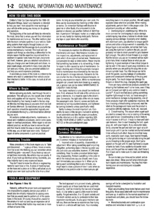 2
2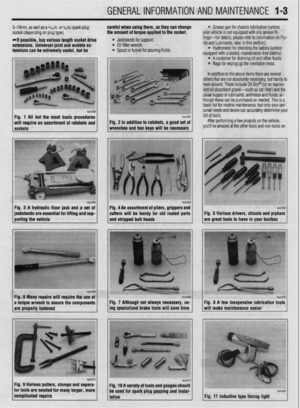 3
3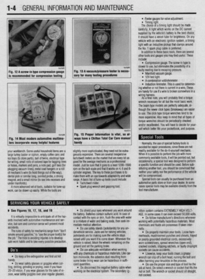 4
4 5
5 6
6 7
7 8
8 9
9 10
10 11
11 12
12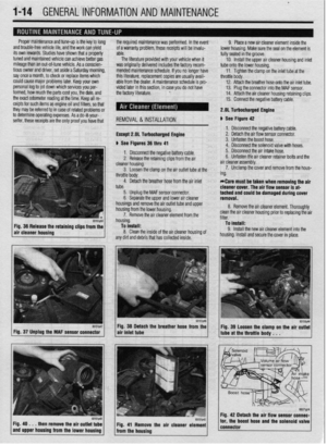 13
13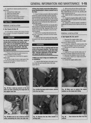 14
14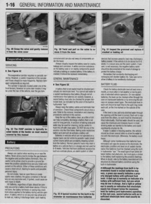 15
15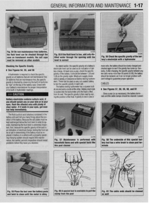 16
16 17
17 18
18 19
19 20
20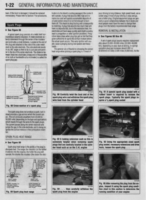 21
21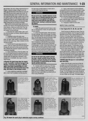 22
22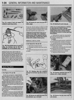 23
23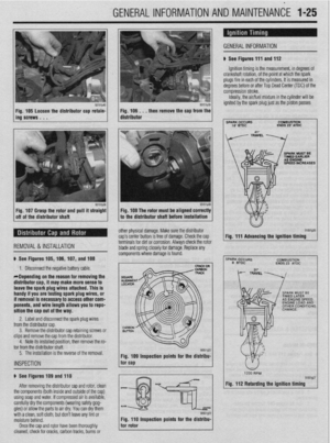 24
24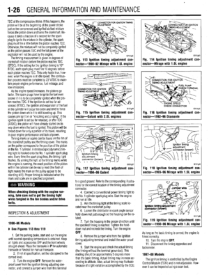 25
25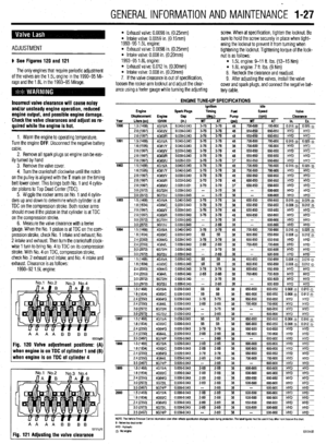 26
26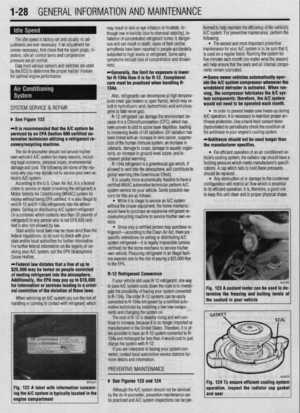 27
27 28
28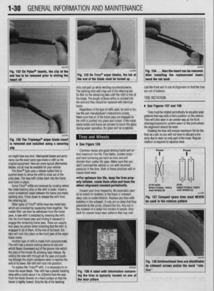 29
29 30
30 31
31 32
32 33
33 34
34 35
35 36
36 37
37 38
38 39
39 40
40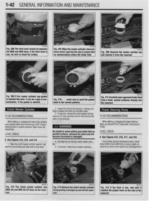 41
41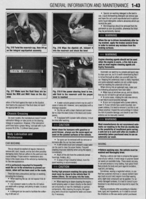 42
42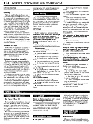 43
43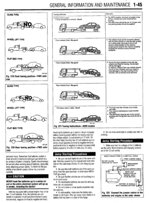 44
44 45
45 46
46 47
47 48
48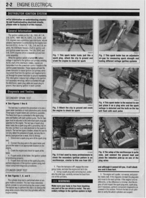 49
49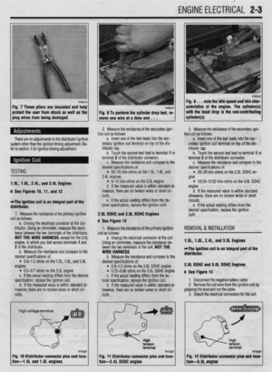 50
50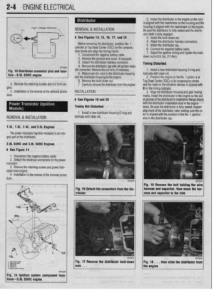 51
51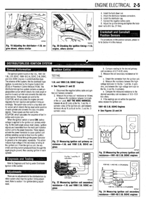 52
52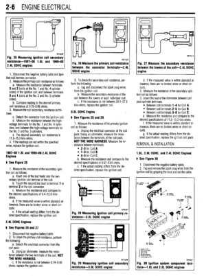 53
53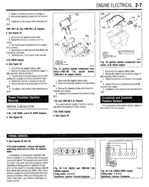 54
54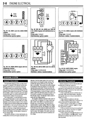 55
55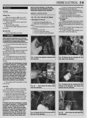 56
56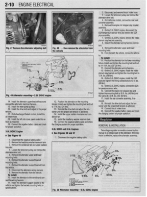 57
57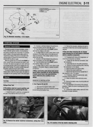 58
58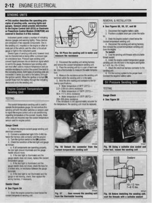 59
59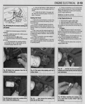 60
60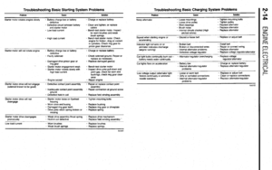 61
61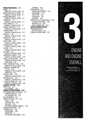 62
62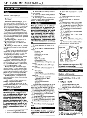 63
63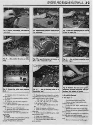 64
64 65
65 66
66 67
67 68
68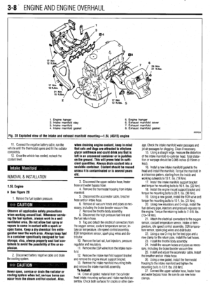 69
69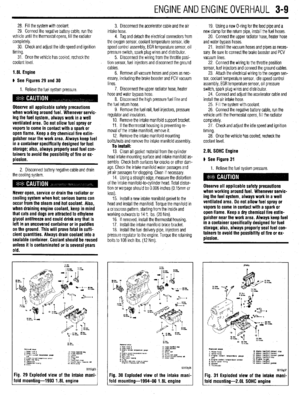 70
70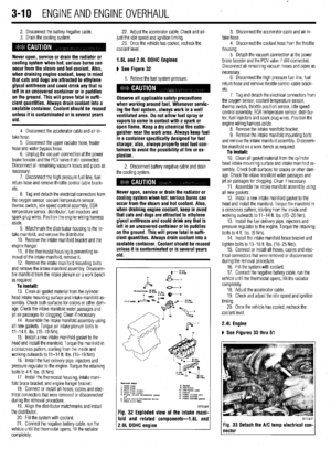 71
71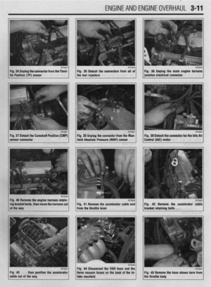 72
72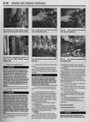 73
73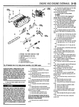 74
74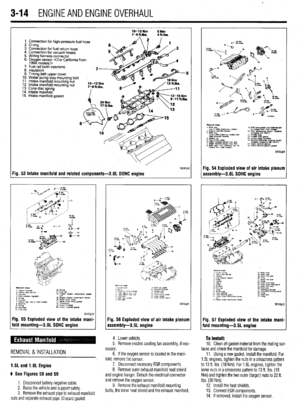 75
75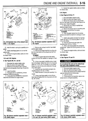 76
76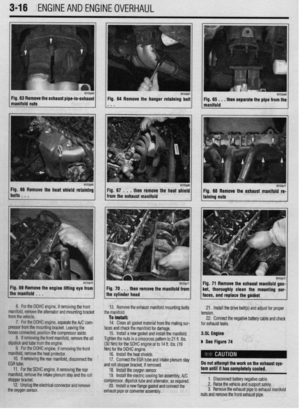 77
77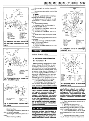 78
78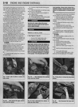 79
79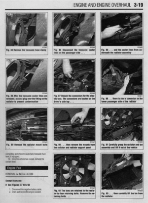 80
80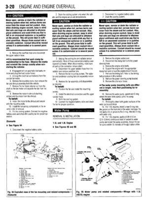 81
81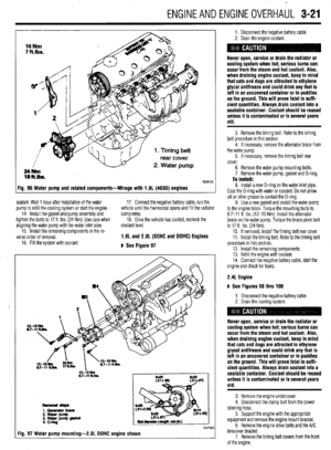 82
82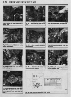 83
83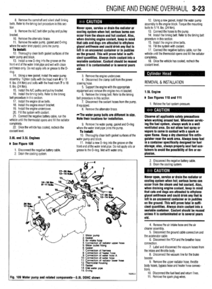 84
84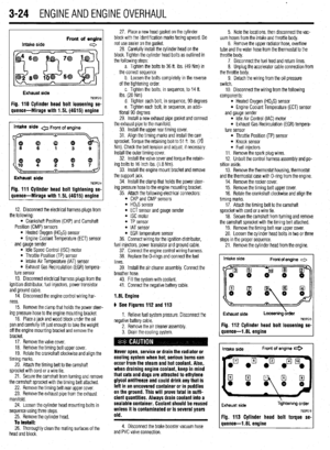 85
85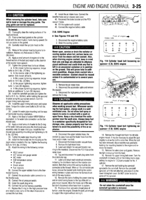 86
86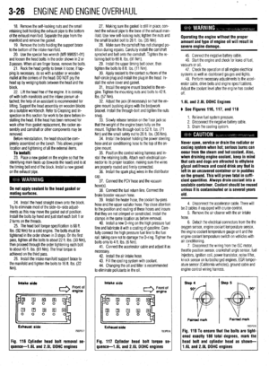 87
87 88
88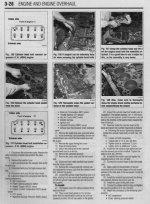 89
89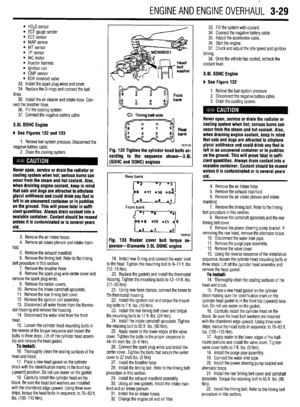 90
90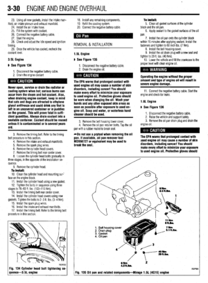 91
91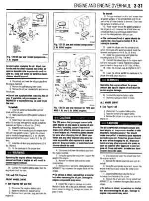 92
92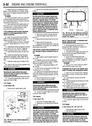 93
93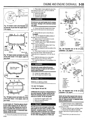 94
94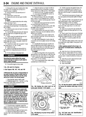 95
95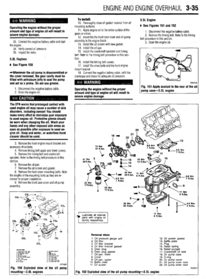 96
96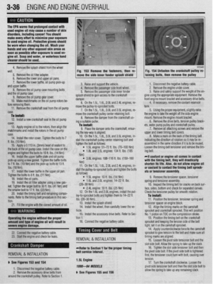 97
97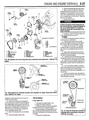 98
98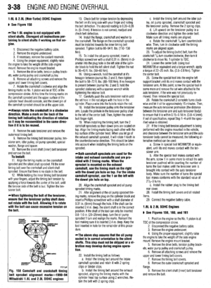 99
99 100
100 101
101 102
102 103
103 104
104 105
105 106
106 107
107 108
108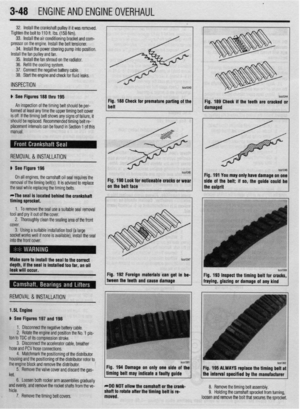 109
109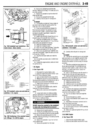 110
110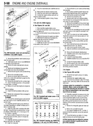 111
111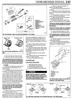 112
112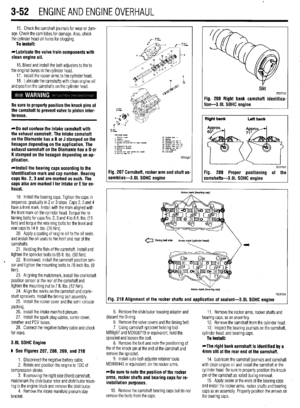 113
113 114
114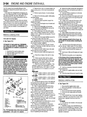 115
115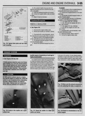 116
116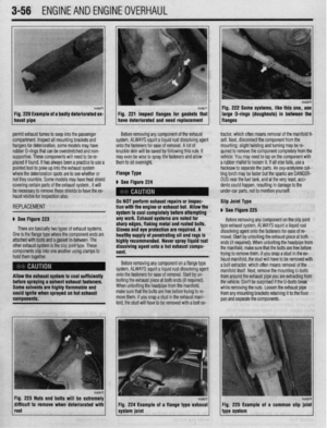 117
117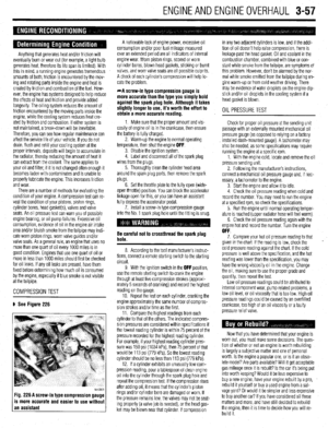 118
118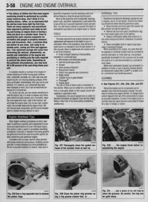 119
119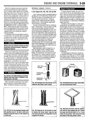 120
120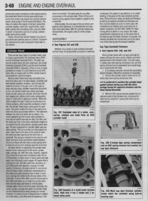 121
121 122
122 123
123 124
124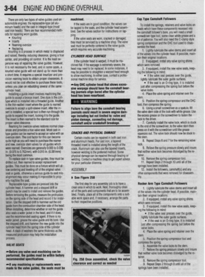 125
125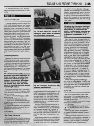 126
126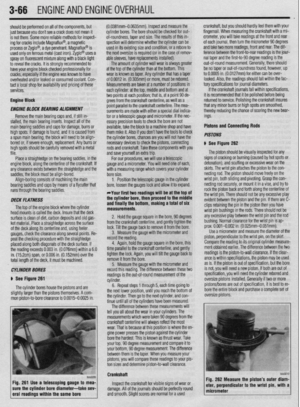 127
127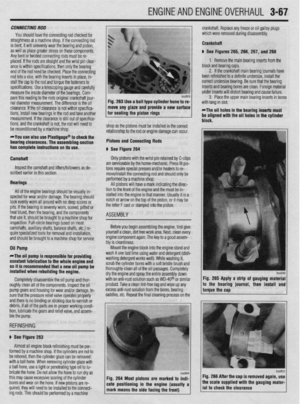 128
128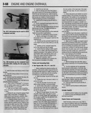 129
129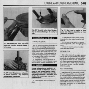 130
130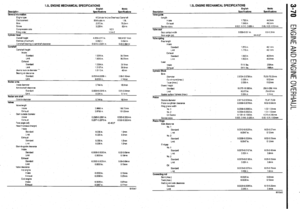 131
131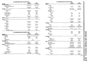 132
132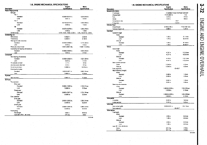 133
133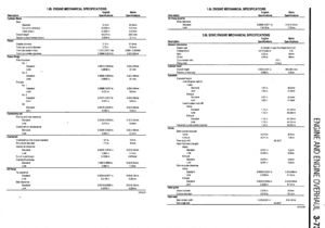 134
134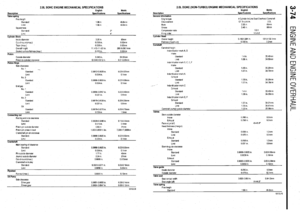 135
135 136
136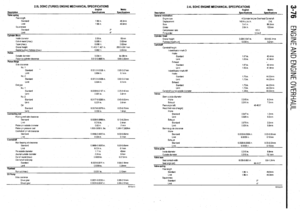 137
137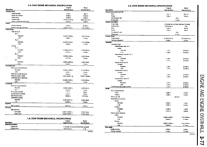 138
138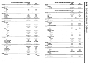 139
139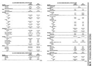 140
140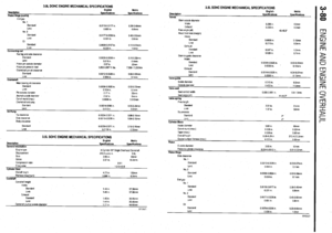 141
141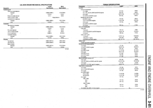 142
142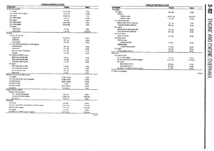 143
143 144
144 145
145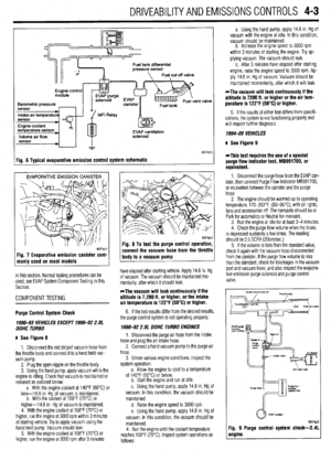 146
146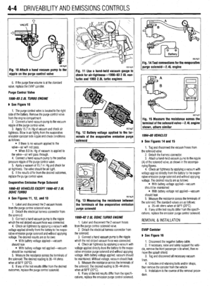 147
147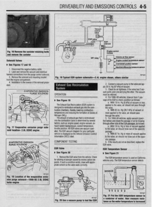 148
148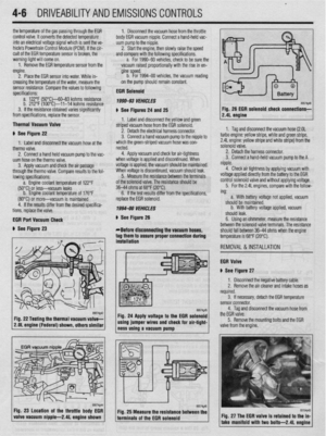 149
149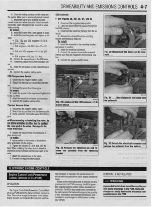 150
150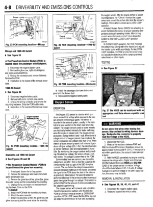 151
151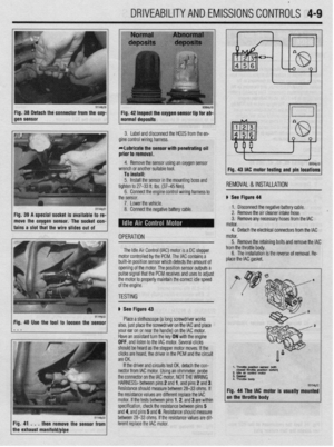 152
152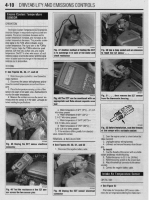 153
153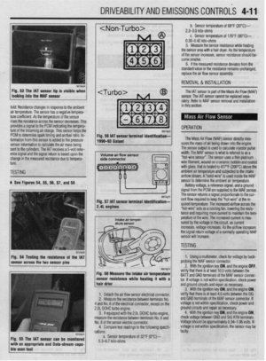 154
154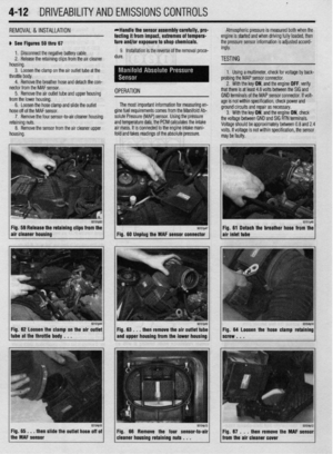 155
155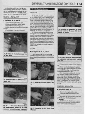 156
156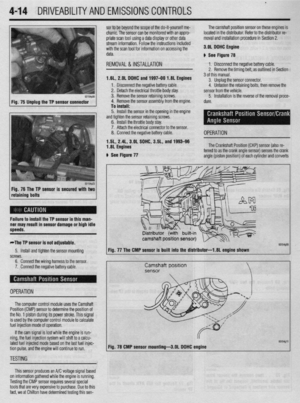 157
157 158
158 159
159 160
160 161
161 162
162 163
163 164
164 165
165 166
166 167
167 168
168 169
169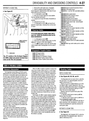 170
170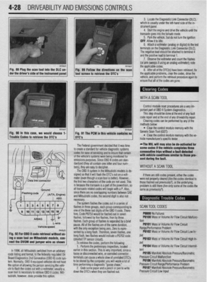 171
171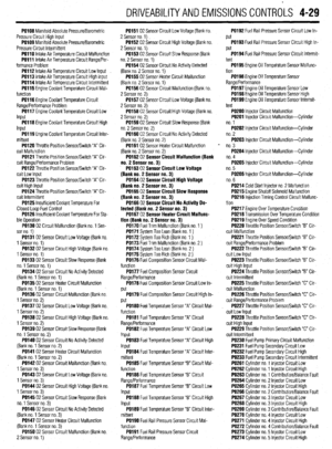 172
172 173
173 174
174 175
175 176
176 177
177 178
178 179
179 180
180 181
181 182
182 183
183 184
184 185
185 186
186 187
187 188
188 189
189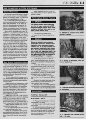 190
190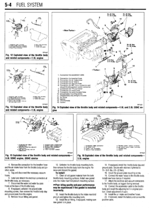 191
191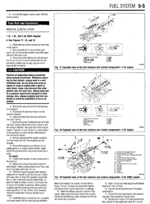 192
192 193
193 194
194 195
195 196
196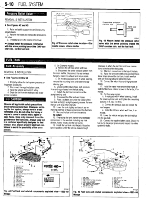 197
197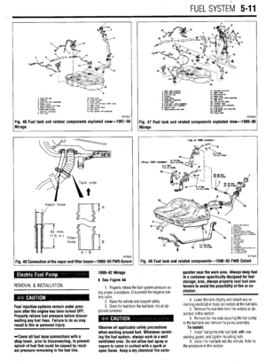 198
198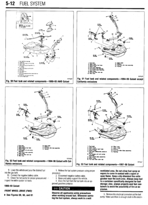 199
199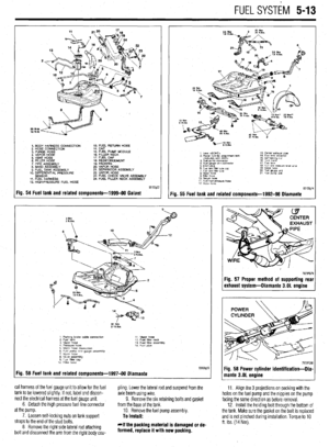 200
200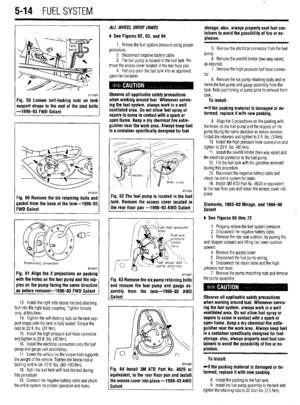 201
201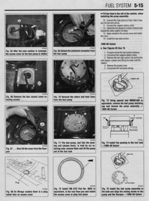 202
202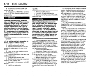 203
203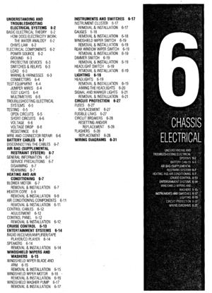 204
204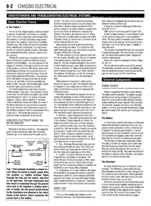 205
205 206
206 207
207 208
208 209
209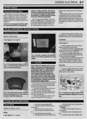 210
210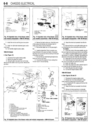 211
211 212
212 213
213 214
214 215
215 216
216 217
217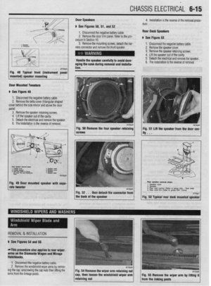 218
218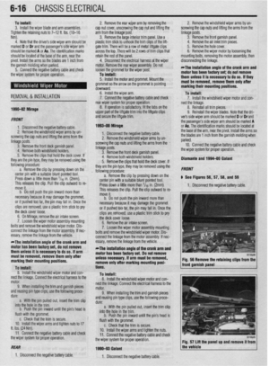 219
219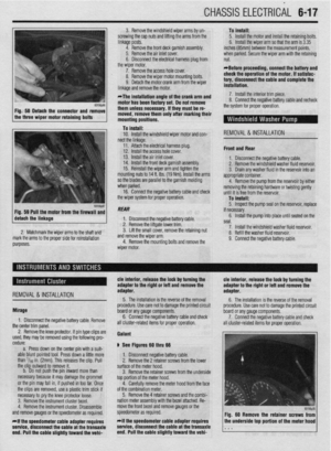 220
220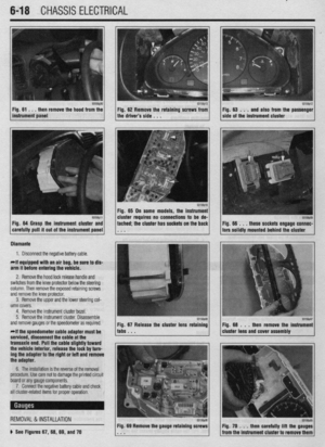 221
221 222
222 223
223 224
224 225
225 226
226 227
227 228
228 229
229 230
230 231
231 232
232 233
233 234
234 235
235 236
236 237
237 238
238 239
239 240
240 241
241 242
242 243
243 244
244 245
245 246
246 247
247 248
248 249
249 250
250 251
251 252
252 253
253 254
254 255
255 256
256 257
257 258
258 259
259 260
260 261
261 262
262 263
263 264
264 265
265 266
266 267
267 268
268 269
269 270
270 271
271 272
272 273
273 274
274 275
275 276
276 277
277 278
278 279
279 280
280 281
281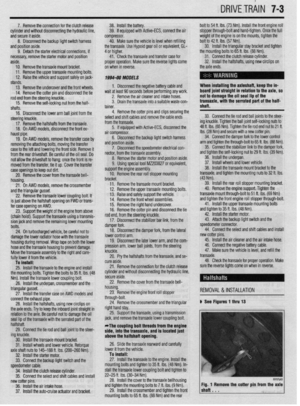 282
282 283
283 284
284 285
285 286
286 287
287 288
288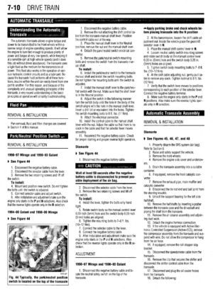 289
289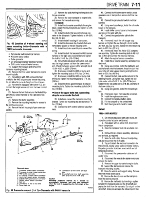 290
290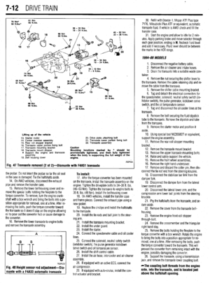 291
291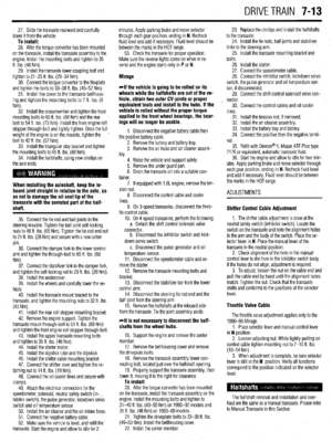 292
292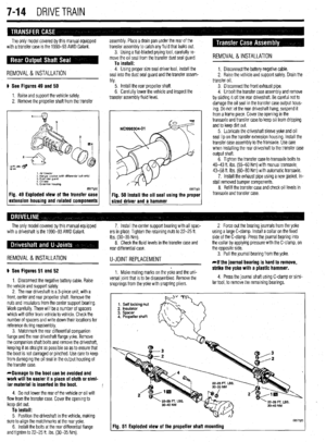 293
293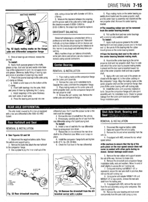 294
294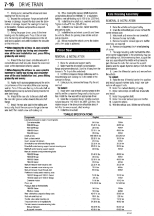 295
295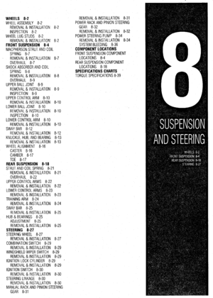 296
296 297
297 298
298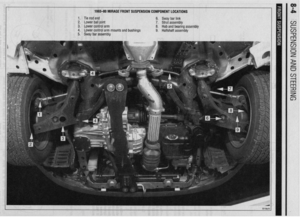 299
299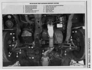 300
300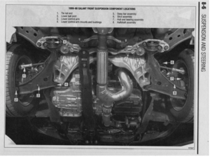 301
301 302
302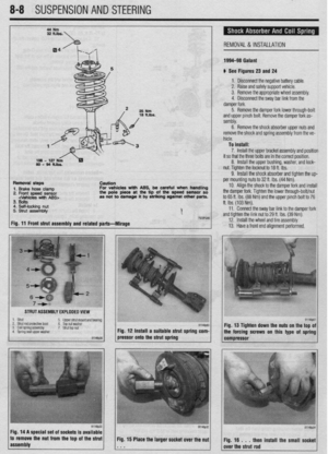 303
303 304
304 305
305 306
306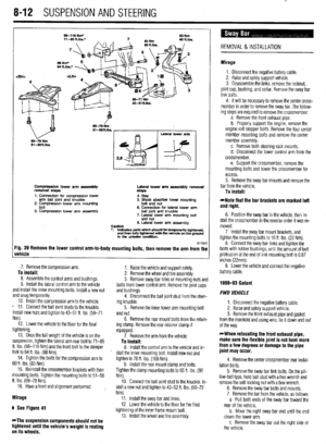 307
307 308
308 309
309 310
310 311
311 312
312 313
313 314
314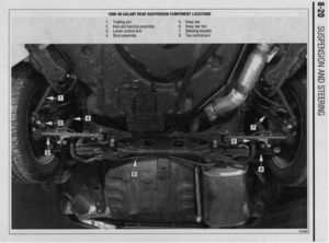 315
315 316
316 317
317 318
318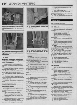 319
319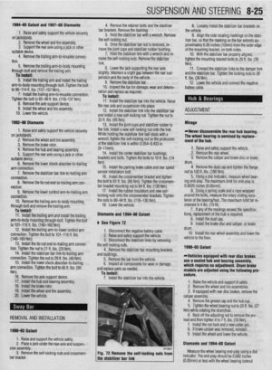 320
320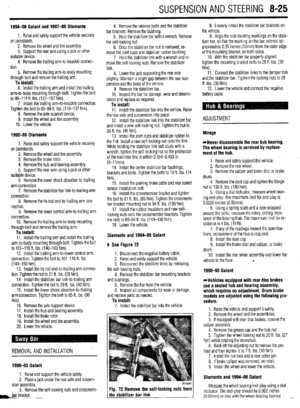 321
321 322
322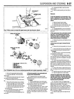 323
323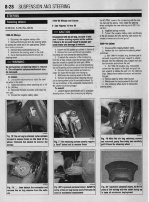 324
324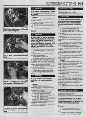 325
325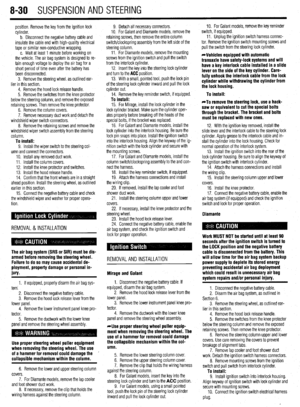 326
326 327
327 328
328 329
329 330
330 331
331 332
332 333
333 334
334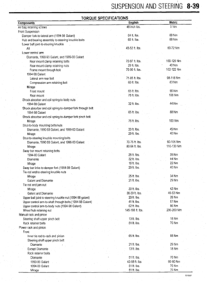 335
335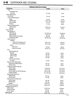 336
336 337
337 338
338 339
339 340
340 341
341 342
342 343
343 344
344 345
345 346
346 347
347 348
348 349
349 350
350 351
351 352
352 353
353 354
354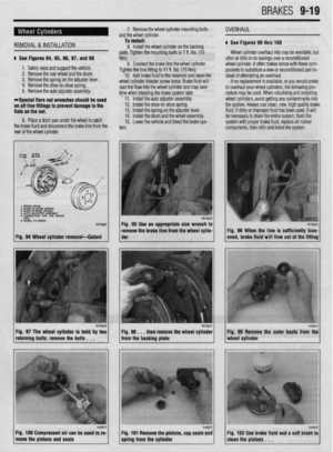 355
355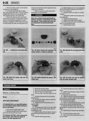 356
356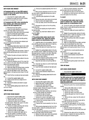 357
357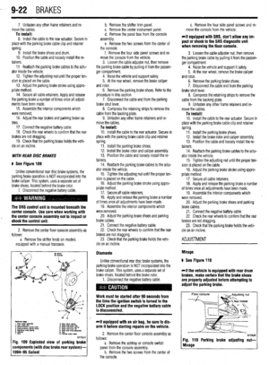 358
358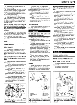 359
359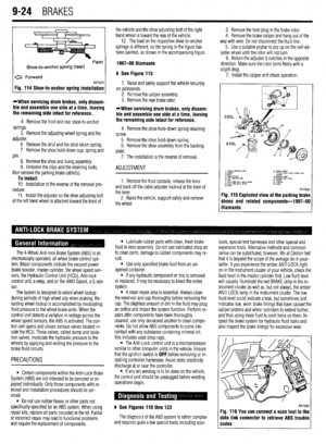 360
360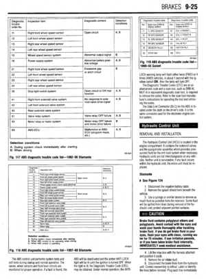 361
361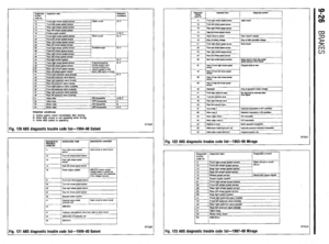 362
362 363
363 364
364 365
365 366
366 367
367 368
368 369
369 370
370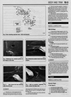 371
371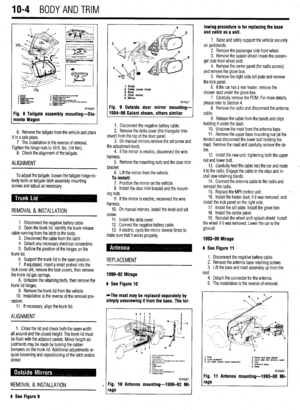 372
372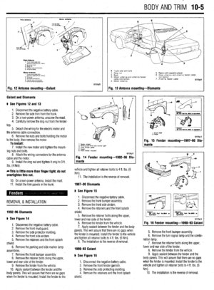 373
373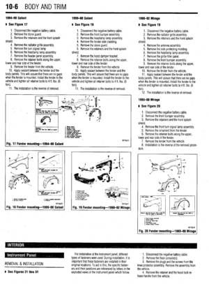 374
374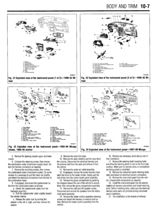 375
375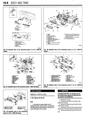 376
376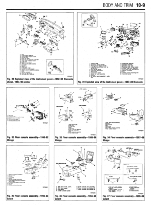 377
377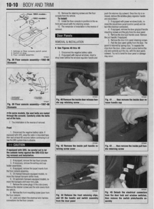 378
378 379
379 380
380 381
381 382
382 383
383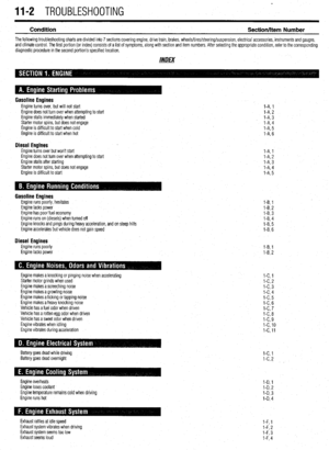 384
384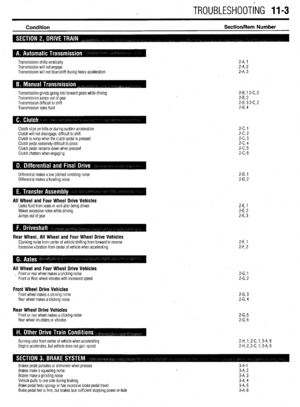 385
385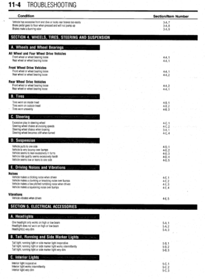 386
386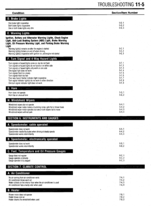 387
387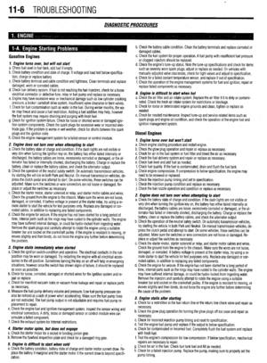 388
388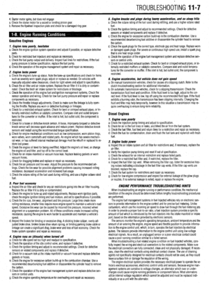 389
389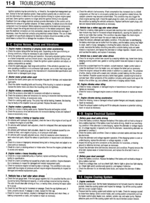 390
390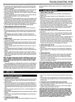 391
391 392
392 393
393 394
394 395
395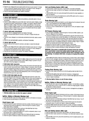 396
396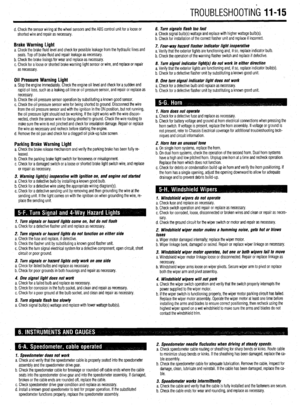 397
397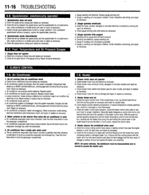 398
398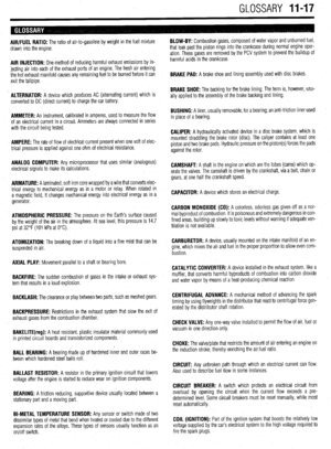 399
399 400
400 401
401 402
402 403
403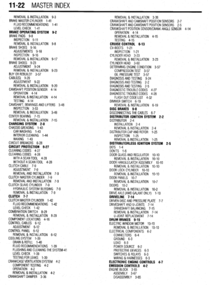 404
404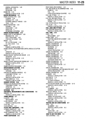 405
405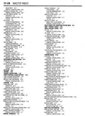 406
406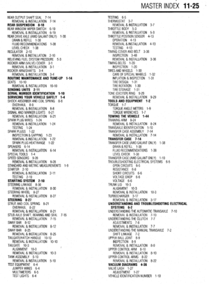 407
407