Page 281 of 408

7-2 'DRIVETRAIN
Because of the way an internal combustron engine
breathes, it can produce torque, or twisting force,
only within a narrow speed range. Most modern,
overhead valve pushrod engines must turn at about
2500 rpm to produce their peak torque By 4500 rpm
they are producrng so lrttle torque that contrnued in-
creases in engine speed produce no power increases.
The torque peak on overhead camshaft engines IS
generally much higher, but much narrower.
The manual transaxle and clutch are employed to
vary the relationship between engine speed and the
speed of the wheels so that adequate engine power can
be produced under all crrcumstances. The clutch al-
lows engine torque to be applied to the transaxle input
shaft gradually, due to mechanical slippage. Conse-
quently, the vehicle may be started smoothly from a
full stop The transaxle changes the ratio between the
rotating speeds of the engine and the wheels by the
use of gears. The gear ratios allow full engine power to
be applied to the wheels during acceleration at low
speeds and at highway/passing speeds.
In a front wheel drive transaxle, power is usually
transmitted from the input shaft to a mainshaft or out-
put shaft located slightly beneath and to the side of
the input shaft. The gears of the mainshaft mesh with
gears on the input shaft, allowing power to be carried
from one to the other. All forward gears are in con-
stant mesh and are free from rotating with the shaft
unless the synchronizer and clutch IS engaged. Shaft-
ing from one gear to the next causes one of the gears
to be freed from rotating with the shaft and locks an-
other to it. Gears are locked and unlocked by internal
dog clutches which slide between the center of the
gear and the shaft. The forward gears employ syn-
chronizers; friction members which smoothly bring
gear and shaft to the same speed before the toothed
dog clutches are engaged.
SHIFT LINKAGE
1. Disconnect the shift linkage from the transaxle.
2. On the transaxle, put select lever in N and
move the shift lever in
4th gear. Depress the clutch,
if necessary, to shift.
3. Move the shift lever in the vehicle to the
4th gear position until it contacts the stop.
4. Turn the adjuster turnbuckle so the shift cable
eye aligns with the eye in the gear shift lever. When
installing the cable eye, make sure the flange side of
the plastic bushing at the shift cable end is on the
cotter pin side.
5 The cables should be adjusted so the clear-
ance between the shift lever and the 2 stoppers are
equal when the shift lever IS moved to 3rd and 4th
gear. Move the shift lever to each positron and check i
that the shifting is smooth
REMOVAL &INSTALLATION
1, Disconnect the negative battery cable 2. Remove any components necessary to access
the back-up light switch.
3. Unplug the back-up light switch connector.
4. Remove the switch from the case using the ap-
propriate size socket and drive tool.
To install: 5. Install the switch and tighten it to 22-25 ft. Ibs.
(30-35 Nm).
6. Attach the back-up light switch connector
7. Install any components removed to access the
back-up light switch
8. Connect the negative battery cable.
REMOVAL & INSTALLATION
Mirage
*If the vehicle is going to be roiled while the
halfshafts are out of the vehicle, obtain 2 outer
CV-joints or proper equivalent tools and install
to the hubs. If the vehicle is rolled without the
proper torque applied to the front wheel bear-
ings, the bearings will no longer be usable.
*The suspension components should not be
tightened until the vehicles weight is resting
on the ground.
1. Remove the battery and battery tray.
2. Remove the air cleaner assembly and vacuum
hoses.
3. Note the locations and disconnect the shifter
cables.
4. If equipped with 1.61 engine, remove the ten-
sion rod.
5. Detach the backup lamp switch connector,
speedometer cable connection and remove the starter
motor.
6. Raise the vehicle and support safely.
7. Remove the front wheels and the inner wheel
panels.
8. Remove the undercover and splash pan.
9. Drain the transaxle oil into a suitable con-
tainer
10. Support the engine and remove the cross-
member.
11. Remove the upper transaxle mounting bolt
and bracket.
12 Disconnect the stabilizer bar, tie rod ends and
the lower ball joint connections.
13 Remove the clutch release cylinder and clutch
oil line bracket. Do not disconnect the fluid lines and
secure the slave cylinder with wire.
14 Disconnect the clutch cable, if equipped with
cable controlled clutch system.
15. Remove the halfshafts by inserting a prybar
between the transaxle case and the driveshaft and
prying the shaft from the transaxle. Do not pull on the
driveshaft Doing so damages the inboard joint. Do
not insert the prybar so far the oil seal in the case is
damaged.
*It is not necessary to disconnect the half-
shafts from the steering knuckle. Remove the
shaft with the hub and knuckle as an assem-
bly. Tie the shafts aside. Note the circle clip
on the end of the inboard shafts should not
be reused.
16. Remove the bellhousing lower cover.
17 Remove the transaxle to engine bolts and
lower the transaxle from the vehrcle.
To install:
*When installing the transaxle, be sure to
align the splines of the transaxle with the
clutch disc.
18 Install the transaxle to the engine and install
the mounting bolts. Tighten the bolts to 31-40 ft. Ibs.
(43-55 Nm) on 1990-92 models and 35 ft. Ibs. (48
Nm) on 1993-00 models.
19 Install the bellhousing cover.
*When installing the halfshafts, use new
circlips on the axle ends. Care must be taken
to ensure that the oil seal lip of the transaxle
is not damaged by the serrated part of the
driveshaft.
20. Install and fully seat the halfshafts into the
transaxle.
21. Install the slave cylinder.
22. Connect the ball joints, tie rod ends and the
stabilizer bar connections.
23. Install the upper transaxle mounting bracket
and bolt.
24. Install the crossmember.
25. Install the undercover.
26. Install the upper transaxle-to-engine mount-
ing bolts, Tighten the bolts to 31-40 ft. Ibs. (43-55
Nm) on 199C-92 models and 35 ff. Ibs. (48 Nm) on
1993-00 models.
27. Install the starter motor.
28 Connect the backup light switch connector
and speedometer cable.
29 Connect and adjust the shifter cables.
30 Install the air cleaner assembly.
31. Install the front wheels.
32 Make sure the vehicle is level when refilling
the transaxle Use Hypoid gear oil or equivalent, GL-
4 or higher.
33. Connect the negative battery cable and check
the transaxle for proper operation. Make sure the re-
verse lights operate when in reverse.
Galant
1999-93 MODELS
rlf the vehicle is going to be rolled on its
wheels while the halfshafts are out of the ve-
hicle, obtain two outer CV-joints or proper
equivalent tools and install to the hubs. If the
vehicle is rolled without the proper torque
applied to the front wheel bearings, the bear-
ings will no longer be usable.
1. Remove the battery and the air intake hoses.
2. If equipped with Active-ECS, unplug the
compressor wiring.
3. Remove the auto-cruise actuator and under-
hood bracket, located on the passenger side inner
fender well.
4. Drain the transaxle and transfer case fluid, if
equipped, into a suitable waste container.
5. Remove the retainer bolt and pull the
speedometer cable from the transaxle assembly.
6. Remove the cotter pin securing the select and
shift cables and remove the cable ends from the
transaxle.
Page 282 of 408
. Install the front engine roll
cylinder and without disconnecting the hydraulic")
DRIVETRAIN 7-3
7. Remove the connection for the clutch release
38. Install the battery.
bolt to 54 ft. Ibs. (73 Nm). Install the front engine roll
cylinder and without disconnecting the hydraulic line,
39. If equipped with Active-ECS, connect the air
stopper through-bolt and hand-tighten. Once the full
and secure it aside.
compressor.
weight of the engine is on the mounts, tighten the
8. Disconnect the backup light switch harness
40. Make sure the vehicle is level when refilling
bolt to 42 ft. Ibs. (57 Nm).
and position aside.
the transaxle. Use Hypoid gear oil or equivalent, GL-
30.
Install the triangular stay bracket and tighten
9. Detach the starter electrical connections, if
4 or higher.
the mounting bolts to 65 ft. Ibs. (88 Nm).
necessary, remove the starter motor and position
41. Check the transaxle and transfer case for
31. Connect the clutch release cylinder.
aside.
proper operation. Make sure the reverse lights come
32. Install the halfshafts, using new circlips on
10. Remove the transaxle mount bracket.
on when in reverse.
the axle ends.
11. Remove the upper transaxle mounting bolts.
12.
Raise the vehicle and support safely on jack-
1!I94-Ol? MODELS
stands.
13. Remove the undercover and the front wheels. 1. Disconnect the negative battery cable and When histalling the axleshaft, keep the in-
14.
Remove the cotter pin and disconnect the tie wait at least 90 seconds before performing any work. board joint straight in relation to the axle, so
rod end from the steering knuckle. 2. Remove the air cleaner and intake hoses. not to damage the oil seal lip of the
15. Remove the self-locking nut from the half- 3. Drain the transaxle into a suitable waste con- transaxle, with the serrated part of the half-
ShaftS. tainer. shaft.
16.
Disconnect the lower arm ball joint from the 4. Remove the cotter pins and clips securing the
steering knuckle. select and shift cables and remove the cable ends 33. Connect the tie rod and ball joints to the steer-
17. Remove the halfshafts from the transaxle. from the transaxle. ing knuckle. Tighten the ball joint self-locking nuts to
18. On AWD models, disconnect the front ex- 5. If equipped with Active-ECS, disconnect the 48 ft. Ibs. (65 Nm). Tighten the tie rod end nut to 21 ft.
haust pipe. air compressor. Ibs. (28 Nm) and secure with a new cotter pin.
19.
On AWD ‘models, remove the transfer case by 6. Disconnect the backup light switch harness 34.
Connect the damper fork to the lower control
removing the attaching bolts, moving the transfer and position aside. arm and tighten the through-bolt to 65 ft. Ibs. (88 Nm).
case to the left and lowering the front side. Remove it 7. Disconnect the speedometer electrical con- 35.
Connect the stabilizer link to the damper fork,
from the rear driveshaft. Be careful of the oil seal. Do nectar, from the transaxle assembly. and tighten the self-locking nut to 29 ft. Ibs. (39 Nm).
not allow the driveshaft to hang; once the front is re- 8. Remove the starter motor and position aside. 36. Install the underpan.
moved from the transfer, tie it up. Cover the transfer 9. Using special tool M2203827 or equivalent, 37. Install wheels and lower vehicle.
case openings to keep out dirt. support the engine assembly. 38. Install the transaxle mount bracket to the
20.
Remove the cover from the transaxle bell- 10. Remove the rear roll stopper mounting transaxle, and tighten the mounting nuts to 32 ft. Ibs.
housing. bracket. (43 Nm).
21. On AWD models, remove the crossmember 11. Remove the transaxle mount bracket. 39. install the rear roll stopper mounting bracket.
and the triangular gusset. 12. Remove the upper transaxle mounting bolts. 40.
Remove the engine support. Tighten the
22. Remove the transaxle lower coupling bolt. It 13. Raise and safely support the vehicle. transaxle mount through-bolt to 51 ft. Ibs. (69 Nm)
is just above the halfshaft opening on FWD or trans- 14. Remove the front wheel assemblies. and tighten the front engine roll stopper through-bolt.
fer case opening on AWD. 15. Remove the right hand undercover. 41. Install the upper transaxle mounting bolts
23.
Support the weight of the engine from above 16. Remove the cotter pin and disconnect the tie and tighten to 35 ft. Ibs. (48 Nm).
(chain hoist). Support the transaxle using a transmis- rod end, from the steering knuckle. 42. Install the starter motor.
sion jack and remove the remaining lower mounting 17. Disconnect the stabilizer bar link, from the 43. Attach the backup light switch and the
bolts. damper fork. speedometer connector.
24. On turbocharged vehicle, be careful not to 18. Disconnect the damper fork, from the lateral 44.
Connect the select and shift cables and install
damage the lower radiator hose with the transaxle lower control arm. new cotter pins.
housing during removal. Wrap tape on both the lower 19. Disconnect the later lower arm, and the com- 45.
Install the air cleaner and the air intake hose.
hose and the transaxle housing to prevent damage. pression arm, lower ball joints, from the steering 46. Connect the negative battery cable.
Move the transaxle assembly to the right and care- knuckle. 47. Make sure the vehicle is level, and refill the
fully lower it from the vehicle. 20. Pry the halfshafts from the transaxle, and se- transaxle.
To install: cure aside. 48.
Check the transaxle for proper operation. Make
25.
Install the transaxle to the engine and install 21. Remove the connection for the clutch release sure the reverse lights come on when in reverse.
the mounting bolts, Tighten the bolts to 35 ft. Ibs. (48 cylinder and without disconnecting the hydraulic line,
Nm). Install the transaxle lower coupling bolt. secure aside.
26.
Install the underpan, crossmember and the 22. Remove the cover from the transaxle bell-
triangular gusset. housing.
27.
Install the transfer case on AWD models and 23. Remove the engine front roll stopper REMOVAL&INSTALLATION
connect the exhaust pipe. through-bolt.
28.
Install the halfshafts, using new circlips on 24. Remove the crossmember and the triangular ) See Figures 1 thru 13
the axle ends. Try to keep the inboard joint straight in right hand stay.
relation to the axle. Be careful not to damage the oil 25. Support the transaxle, using a transmission
seal lip of the transaxle with the serrated part of the jack, and remove the transaxle lower coupling bolt.
halfshaft.
29. Connect the tie rod and ball joint to the steer- *The coupling bolt threads from the englne
side, into the transaxle, and is located just
ing knuckle.
30. Install the transaxle mount bracket. above the halfshaft opening.
31. Install wheels and lower vehicle. Retorque 26. Slide the transaxle rearward and carefully
axle shaft nuts to 145-188 ft. Ibs. (200-260 Nm). lower it from the vehicle.
32. Install the starter motor. To install:
33. Connect the backup light switch and the 27. Install the transaxle to the engine. Install the
speedometer cable. mounting bolts and tighten to 35 ft. Ibs. (48 Nm). In-
34. Install the clutch release cylinder. stall the transaxle lower coupling bolt and tighten to
35.
Connect the select and shift cables and install 22-25 ft. Ibs. (30-34 Nm).
new cotter pins. 28. Install the cover to the transaxle bellhousing
36. Install the air intake hose. and tighten the mounting bolts to 7 ft. Ibs. (9 Nm).
37. Install the auto-cruise actuator and bracket. 29. Install the crossmember and tighten the front
mounting bolts to 65 ft. Ibs. (88 Nm) and the rear
Page 283 of 408
.
7-4 DRIVETRAIN
Fig. 2 . . . then loosen the axle nut while
the vehicle is still on the ground
Fig. 5 Remove the lower coil-over shock
lower mounting bolt and nut from the con-
trol arm
I
93157po7 Fig. 8 Use a suitable prytool to release the
inner CV-joint retaining ring from the
transaxle by gently prying outward
Fig, 11 , , .
then slide the halfshaft out of
the knuckle Fig. 9 Remove the inner joint from the
transaxle until the spline completely clears
the transaxle Fig. 7 . . , the lot Fig. 7 . . / the lower ball joints from the
steering knuckle steering knuckle 93157pcn Fig. 10 Uslng a suitable punch and ham-
mer, gently tap the halfshaft out of the
steering knuckle . . .
I I Fig, 13 Always replace the clrcllp on the in-
Fig. 12 Remove the halfshaft from the ve- ner joint before installing the shaft Into the
hlcle transaxle
Page 284 of 408

DRIVETRAIN 7-5
1, While the vehicle is still on the ground, re- IO. Insert the halfshaft into the tram&e. Be sure cle is being serviced could make a difference in joint
move the cotter pin, and loosen the axle nut. it is fully seated. type. Be sure to properly identify the joint before at-
2. Raise the vehicle and support it safely. 1 I. Pull the strut assembly out and install the tempting joint or boot replacement. Look for identifi-
3. If equipped with ABS, remove the front wheel other end to the hub. cation numbers at the large end of the boots and/or
speed sensor. 12. Install the center bearing bracket bolts and on the end of the metal retainer bands.
4. If equipped with Active Electronic Control tighten to 33 ft. Ibs. (45 Nm). The 3 types of joints used are the Birfield Joint,
Suspension (Active-ECS), perform the following: 13. Install the washer on the axle shaft so the (B.J.), the Tripod Joint (T.J.) and the Double Offset
a. Loosen the nut that secures the air line to chamfered edge faces outward. Install the axle nut, Joint (D.O.J.).
the to the top of the strut and discard the O-ring.
b. Remove the bolts that secure the actuator but do not tighten it fully at this time.
14. Connect the ball joint to the steering knuckle. *Do not disassemble a Birfield joint. Ser-
to.the top of the strut and remove the compo-
Torque the new retaining nut to 43-52 ft. Ibs. (68-72 vice with a new joint or clean and repack us-
nent. Disconnect the wiring harness.
Nm) and secure with a new cotter pin. ing a new boot kit.
5. Disconnect the lower ball joint and the tie rod
15. Connect the tie rod end to the steering
The distance between the large and small boot
end from the steering knuckle.
knuckle. Torque the retaining nut to 21 ft. Ibs. (29
bands is important and should be checked prior to
6. Remove the axle nut and the washer.
Nm) and secure with a new cotter pin.
and after boot service. This is so the boot will not be
7. If removing the left side axle with an inner 16. If equipped with ABS, install the front wheel
installed either too loose or too tight, which could
shaft, remove the center support bearing bracket speed sensor.
cause early wear and cracking, allowing the grease to
bolts and washers. Then, remove the halfshaft by set-
17. If equipped with Active-KS, perform the fol- get out and water and dirt in, leading to early joint
ting up a puller on the outside wheel hub and push-
lowing:
failure.
ing the halfshaft from the front hub. Tap the shaft a. Install the air line with a new O-ring.
union at the joint case with a plastic hammer to re- b. Install the actuator to the top of the strut. *The drfveshaft joints use special grease;
move the halfshaft and inner shaft from the transaxle. Connect the wiring harness. do not add any grease other than that sup-
8. If removing right side axle shafts without an 18. Install the wheel and lower the vehicle to the plied with the kit.
inner shaft, remove the halfshaft by setting up a floor.
puller on the outside wheel hub and pushing the half- 19. Tighten the axle nut to 145-188 ft. Ibs.
Double Offset Joint
shaft from the front hub. After pressing the outer (200-260 Nm) and secure with a new cotter pin.
shaft, insert a prybar between the transaxle case and The Double Offset Joint (D.O.J.) is bigger than
the halfshaft and pry the shaft from the transaxle.
CV-JOINTS OVERHAUL other joints and, in these applications, is normally
*Do not pull on the shaft; doing so damages used as an inboard joint.
the inboard joint. b See Figures 14 thru 27 1. Remove the halfshaft from the vehicle.
2. Side cutter pliers can be used to cut the metal
To install: These vehicles use several different types of joints. retaining bands. Remove the boot from the joint outer
9. Replace the circlips on the ends of the half- Engine size, transaxle type, whether the joint is an in- race.
shafts. board or outboard joint, even which side of the vehi-
TCCS7030 TCCS7031
I I TCCS7032 Fig. 15 Removing the outer band from the
Fig. 16 Removing the inner band from the
Fig. 14 Check the CV-boot for wear
W-boot
lho~sing IFi7~ / Fig 17 Removing the CV-boot from the joint 1 1 CV-boot
TCCS7035 Fig 18 Clean the CV-joint housing prior to
removing boot Tccs7W 1 1 sembiy Fig 19 Removing the CV-joint housing as-
Page 285 of 408

-
7-6 DRIVETRAIN
fig. 20 Removing the CV-joint Fig. 21 inspecting the M-joint housing
TCCS7042 1 Fig. 26 Removing the CV-joint inner
snapring Fig, 27 installing the CV-joint assembly Removing the CV-joint outer
Fig. 25 Removing the CV-joint assembly
11. Install the halfshaft to the vehicle.
Except Double Otfset Joint
1. Disconnect the neaative batterv cable. Remove
the halfshaft. - ’
2. Use side cutter oliers to remove the metal re-
taining bands from the boot(s) that will be removed.
Slide the boot from the T.J. case.
3. Remove the snapring and the tripod joint spi-
der assembly from the halfshaft. Do not disassemble
the spider and use care in handling.
4. If the boot is be reused, wrap vinyl tape around
the spline part of the shaft so the boot(s) will not be
I
3. Locate and remove the large circlip at the ’
base of the joint. Remove the outer race (the body of
the joint).
4. Remove the small snapring and take off the
inner race, cage and balls as an assembly. Clean the
inner race, cage and balls without disassembling.
5. If the boot is to be reused. wioe the arease
from the splines and wrap the splfnes in vin$ tape
before sliding the boot from the shaft.
6. Remove the inner (D.O.J.) boot from the
shaft. If the outer (B.J.) boot is to be replaced, re-
move the boot retainer rings and slide the boot down
and off of the shaft at this time.
To install:
7. Be sure to tape the shaft splines before in-
stalling the boots. Fill the inside of the boot with the (typiW
1
specified grease. Often the grease supplied in the re-
placement parts kit is meant to be divided in half,
with half being used to lubricate the joint and half be-
ing used inside the boot.
Install the cage onto the halfshaft so the small 8.
diameter side of the cage is installed first. With a
brass drift pin, tap lightly and e ’ ’ ‘* ’
nemy arouna me Inner
race to install the race until it comes into contact with
the rib of the shaft. Apply the specified grease to the
inner race and cage and fit them together. Insert the
balls into the cage.
9. Install the outer race (the body of the joint)
after filling with the specified grease. The outer race
should be filled with this greas e.
10. Tighten the boot bands
securely. Make sure
the distance between the boot t,, IuJ IJ ,,“I lGbl. \onrlo i.i *nrro”+ damaged when removed. Remove the dynamic
To install: damper, if used, and the boots from the shaft.
5. -
Double check that the correct replacement
parts are being installed. Wrap vinyl tape around the
splines to protect the boot and install the boots and
damper, if used, in the correct order,
6. Install the joint spider assembly to the shaft
and ipctdl the cnmrinn 7. Fill the inside ofthe boot with the specified
grease. Often the grease supplied in the replacement
parts kit is meant to be divided in half, with half being
used to lubricate the joint and half being used inside
the boot. Keep grease off the rubber part of the dy-
namic damper (if used).
8. Secure the boot bands with the halfshaft in a
horizontal position. Make sure distance between boot
bands is correct.
9. Install the halfshaft to the vehicle and recon-
nect
the negative battery cable.
Page 286 of 408
 discon-
necti
M no the enoine from the transaxie.- .
The clutch driven disc mav co")
DRlVETRilN 7-7
bansaxle. When the pedal is pushed inward, the disc
and plate separate (the clutch is disenqaqed) discon-
necti
M no the enoine from the transaxie.- .
The clutch driven disc mav comam asoestos.
Galant and Mirage
b See Figures 28 thru 41 ost clutches utilize a single plate, dry friction REMOVAL &INSTALLATION
.* * _ disc with a diaphragm-style spring pressure plate.
which has been determined to be a cancer ’ The clutch disc has a splined hub which attaches the
causing agent. Never clean clutch surfaces disc to the input shaft. The disc has friction material
with compressed air! Avoid inhaling any dust where it contacts the flywheel and pressure plate.
from any clutch surface! When cleaning Torsion springs on the disc help absorb engine
clutch surfaces, use a commercially avail- torque pulses. The pressure plate applies pressure to
able brake cleaning fluid. the clutch disc, holding it tight againstthe surface of
the flywheel. The clutch operating mechanism con-
sists of a release bearing, fork and cylinder assembly. The clutch driven disc may contain asbestos,
The purpose of the clutch is to disconnect and
The release fork and actuating linkage transfer which has been determined to be a cancer
connect engine power at the tram&e. A vehicle at
pedal motion to the release bearing. In the engaged causing agent. Never clean clutch surfaces
rest requires a lot of engine torque to get all that
weight moving. An internal combustion engine does position (pedal released) the diaphragm spring holds with compressed air! Avoid inhaling any dust
the pressure plate against the clutch disc, so engine from any clutch surface! When cleaning
not develop a high starting torque (unlike steam en-
torque is transmitted to the input shaft. When the clutch surfaces, use a commercially avail-
gines) so it must be allowed to operate without any
clutch pedal is depressed, the release bearing pushes able brake cleaning fluid.
load until it builds up enough torque to move the ve-
hicle. Torque increases with engine rpm. The clutch the diaphragm spring center toward the flywheel. The
diaphragm spring pivots the fulcrum, relieving the 1. Disconnect the negative battery cable.
allows the engine to build up torque by physically
disconnecting the engine from the transaxle, relieving load on the pressure plate. Steel spring straps riveted 2. Raise and safely support the vehicle.
the engine of any load or resistance. to the clutch cover lift the pn--“-- -I-‘^ I--- ‘!-- 3. Remove the transaxle assemblv from the ve-
The transfer of engine power to the transaxle (the clutch disc, disengaging the Gllyl,lo UllVc IIVIII II1c
4. Remove the oressure elate attachina bolts.
load) must be smooth and gradual; if it weren’t, drive transaxle and enabling the gc”-- +,, h,n -‘----’
line components would wear out or break quickly. The clutch is operating pryV’uV,J ,,.
l to be reused, loosen the bolts in a diagonal pattern 1
This gradual power transfer is made possible by It will stall the engine when released with the
vehicle held stationary. or 2 turns at a time. This will prevent warping the
gradually releasing the clutch pedal. The clutch disc
l The shift lever can be moved freely between 1st clutch cover assembly.
and pressure plate are the connecting link between
and reverse gears when the vehicle is stationary and 5. Remove the return clip and the pressure plate
the engine and transaxle. When the clutch pedal is
the clutch disengaged. release bearing. Do not use solvent to clean the bear-
released, the disc and plate contact each other (the ing.
clutch is engaged) ohvsicallv ioinina the enaine and 6. lnsoect the clutch release fork and fulcrum for hicle. Refer to the procedure earlier in this section.
pressure plate and clutch disc. If the pressure plate is
TCCS7118 Fig. 28 Loosen and remove the clutch and
. . . then carefully remove the clutch
essure plate bolts evenly, a little at a time
1~~~~~ -1 [it&ouldbeflat and pressure plate assembly from the fly
- ‘(
1 .
Fig. 33 Upon installation, it is usually a 7 1 / F@%!,d . then remove the flywhee;;:! 1 1 pound’to the flywheel bolts . Tccs7’z3~
Ftg. 31 If necessary, lock the flywheel III
the crankshaft m order replace d or have d
place and remove the retaining bolts . . . good Idea to apply a threadlockmg com-
Page 287 of 408

7-8 DRIVETRAIN
/ sive Wear TCCS7124 1 Fig 34 Check the pressure plate for exces- TCCS7126 j / . Fig 38 Be sure that the flywheel surface is
clean, before installing the clutch
Fig. 38 Use the clutch alignment tool to
align the
clutch disc during assembly
Fig. 40 You may want to use a threadlock- Fig, 41 Be sure to use a torque wrench to
ing compound on the clutch assembly bolts
tighten all bolts
damage or wear. If necessary, remove the release fork the end of the release cylinder pushrod and the
and unthread the fulcrum from the transaxle. pushrod hole in the release fork.
7. Carefully inspect the condition of the clutch 13. Apply multi-purpose grease to the clutch re-
components and replace any worn or damaged parts.
lease bearing. Pack the bearing inner surface and the r Fig. 36 Typical clutch alignment tool, note
shaft ,,, 1 how the splines match the transaxle’s input
TCCS7130 Fig. 39 Pressure plate-to-flywheel bolt
holes should align
nodels and 16 ft. Ibs. (22 Nm) on all other models.
3emove the aligning tool.
. 18. Install the transaxle assembly.
19. Check for proper clutch operation.
4DJUSTMENTS
Pedal Free Play
1. Measure the clutch pedal height from the face
of the pedal pad to the firewall. The desired distances
are as follows:
a. Mirage--&6148 in. (168-171mm)
b. Galant -6.93-7.17 in. (176182mm)
2. Measure the clutch pedal clevis pin play at the
ace of the pedal pad. The standard values are as fol-
DWS: a. Mirage--0.04--0.12 in. (l-3mm)
b. Galant4.04-0.12 in. (l-3mm)
3. If the clutch pedal height or clevis pin play are
rot within the standard values, adjust as follows:
Page 288 of 408

DRIVETRAIN 7-9
*When adjusting the clutch pedal height or
the clutch pedal clevis pin play, be careful
not to push the pushrod toward the master
cylinder.
d. Check that when the clutch pedal is de-
pressed all the way, the interlock switch switches
over from ON to OFF.
ADJUSTMENT
# See Figure 42
*The following adjustment is for the cable
actuated clutch system on the Mirage. The
Hydraulic systems on all other models are
self-adjusting.
1. Measure the clutch pedal height (measurement
A). The specificatron is 6.38-6.50 in.
(162-165mm).
*The clutch pedal height is not adjustable.
If not within specifications, part replacement
is required.
2. Depress clutch pedal several times and check
the pedal free-play (measurement B).
3. If measurement is not 0.67-0.87 in.
(17-22mm), adjustment is required.
4. To adjust, turn the outer cable adjusting nut,
located at the firewall, until free-play is within range.
5. Depress the clutch pedal several times and
recheck the measurement.
REMOVALANDINSTALLATION
1. Rotate the adjusting wheel counterclockwise to
loosen the cable.
2. Remove the cable retaining clamps.
3. Remove the cotter pin from the clutch actuat-
ing arm at the transaxle and disconnect the cable.
4. Disconnect the cable at the pedal and remove
the cable from the vehicle.
rln order to prevent cable binding or abra-
sion, be sure to take note of the cable rout-
ing, so that it can be reinstalled in the same
position.
To install:
5. Route the cable and make the connection at the
clutch pedal.
6. Make the connection at the transaxle and se-
cure the cable with the retaining clamp. Install a new
cotter pin.
7. Lubricate all pivot points.
8 Adjust the cable to achieve proper free-play.
REMOVAL &INSTALLATION
I
1. Disconnect the negative battery cable.
2. Remove necessary underhood components in
order to gain access to the clutch master cylinder.
Clutch pedal height
Fig. 42 Clutch pedal height (A) measure-
ment-Mirage
7923PGDl
3. Place a suitable drain pan under the vehicle to
catch the fluid once the line IS drsconnected, or place
a rag or shop towel under the fluid line of the master
cylinder.
4. Loosen the line at the cylinder and allow the
fluid to drain.
Clean, high quality brake fluid is essential to
the safe and proper operation of the brake
system. You should always buy the highest
quality brake fluid that is available. If the
brake fluid becomes contaminated, drain and
flush the system, then refill the master cylin-
der with new fluid. Never reuse any brake
fluid. Any brake fluid that is removed from
the system should be discarded. Also, do not
allow any brake fluid to come in contact with
a oainted surface; it will damage the paint.
5. Remove the clevis pin retainer at the clutch
pedal and remove the washer and clevis pm.
6. Remove the 2 nuts and pull the cylinder from
the firewall. A seal should be between the mounting
flange and firewall. This seal should be replaced.
7. The installation is the reverse of the removal
procedure.
8. Lubricate all pivot points with grease.
9. Bleed the system at the slave cylinder using
DOT 3 brake fluid and check the adjustment of the
clutch pedal.
REMOVAL &INSTALLATION
1. Disconnect the negative battery cable
2. Remove necessary underhood components in
order to gain access to the clutch release cylinder.
3. Place a suitable drain pan under the vehicle,
then remove the hydraulic line and allow the system
to drain.
Clean, high quality brake fluid is essential to
the safe and proper operation of the brake
system. You should always buy the highest quality brake fluid that is available. If the
brake fluid becomes contaminated, drain and
flush the system, then refill the master cylin-
der with new fluid. Never reuse any brake
fluid. Any brake fluid that is removed from
the system should be discarded. Also, do not
allow any brake fluid to come in contact with
a uainted surface; it will damage the paint.
4. Remove the bolts and pull the cylinder from
the transaxle housing. On some 1.5L engines, in-
stead of a pushrod bearing against the clutch arm, a
clevis pin and yoke is used. Simply remove the cir-
clip, pull out the clevis pin and remove the cylinder.
5. The installation IS the reverse of the removal
procedure.
6. Lubricate all pivot points with grease.
7. Bleed the system using DOT 3 brake fluid.
HYDRAULIC SYSTEM BLEEDING
) See Figure 43
With Hydraulic Clutch
1, Fill the reservoir with clean brake fluid meeting
DOT 3 specificatrons.
Clean, high quality brake fluid is essential to
the safe and proper operation of the brake
system. You should always buy the highest
quality brake fluid that is available. If the
brake fluid becomes contaminated, drain and
flush the system, then refill the master cylin-
der with new fluid. Never reuse any brake
fluid. Any brake fluid that is removed from
the system should be discarded. Also, do not
allow any brake fluid to come in contact with
a painted surface; it will damage the paint.
2. Press the clutch pedal to the floor, then open
the bleeder screw on the slave cvlinder.
3. Tighten the bleed screw and release the clutch
pedal.
4. Repeat the procedure until the fluid is free of
air bubbles.
7923PG91 Fig. 43 Bleeding a typical clutch hydraulic
system
 1
1 2
2 3
3 4
4 5
5 6
6 7
7 8
8 9
9 10
10 11
11 12
12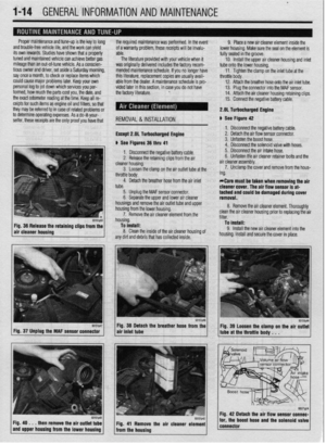 13
13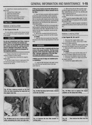 14
14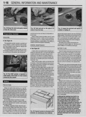 15
15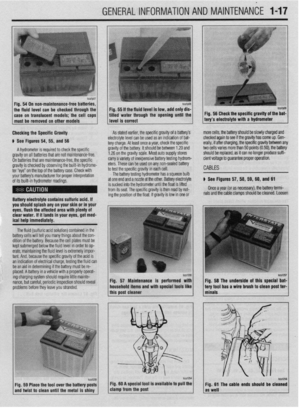 16
16 17
17 18
18 19
19 20
20 21
21 22
22 23
23 24
24 25
25 26
26 27
27 28
28 29
29 30
30 31
31 32
32 33
33 34
34 35
35 36
36 37
37 38
38 39
39 40
40 41
41 42
42 43
43 44
44 45
45 46
46 47
47 48
48 49
49 50
50 51
51 52
52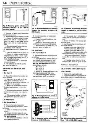 53
53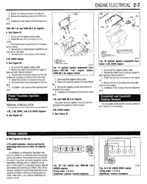 54
54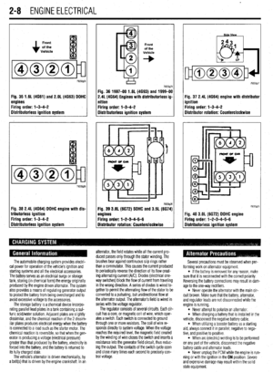 55
55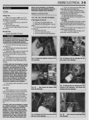 56
56 57
57 58
58 59
59 60
60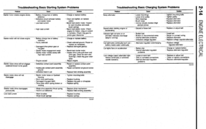 61
61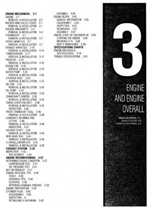 62
62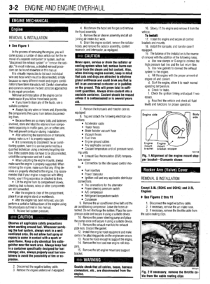 63
63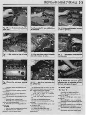 64
64 65
65 66
66 67
67 68
68 69
69 70
70 71
71 72
72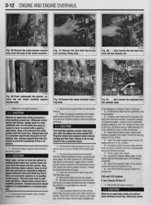 73
73 74
74 75
75 76
76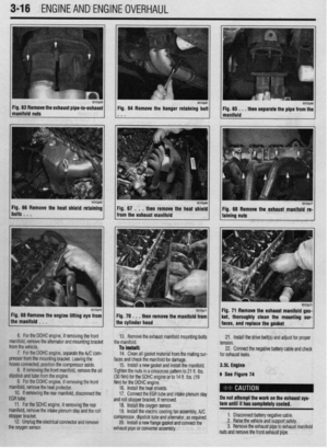 77
77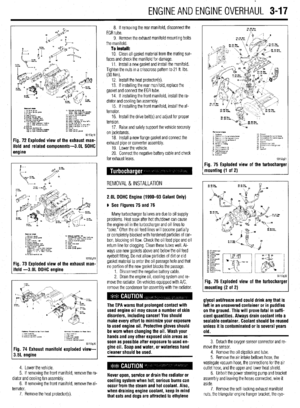 78
78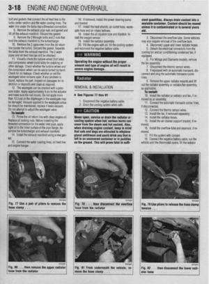 79
79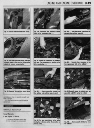 80
80 81
81 82
82 83
83 84
84 85
85 86
86 87
87 88
88 89
89 90
90 91
91 92
92 93
93 94
94 95
95 96
96 97
97 98
98 99
99 100
100 101
101 102
102 103
103 104
104 105
105 106
106 107
107 108
108 109
109 110
110 111
111 112
112 113
113 114
114 115
115 116
116 117
117 118
118 119
119 120
120 121
121 122
122 123
123 124
124 125
125 126
126 127
127 128
128 129
129 130
130 131
131 132
132 133
133 134
134 135
135 136
136 137
137 138
138 139
139 140
140 141
141 142
142 143
143 144
144 145
145 146
146 147
147 148
148 149
149 150
150 151
151 152
152 153
153 154
154 155
155 156
156 157
157 158
158 159
159 160
160 161
161 162
162 163
163 164
164 165
165 166
166 167
167 168
168 169
169 170
170 171
171 172
172 173
173 174
174 175
175 176
176 177
177 178
178 179
179 180
180 181
181 182
182 183
183 184
184 185
185 186
186 187
187 188
188 189
189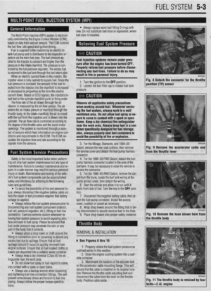 190
190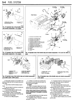 191
191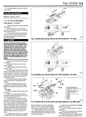 192
192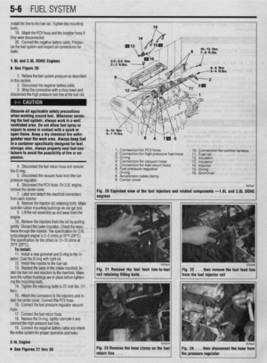 193
193 194
194 195
195 196
196 197
197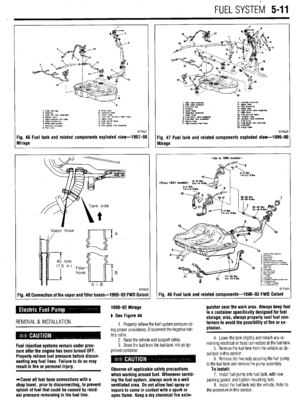 198
198 199
199 200
200 201
201 202
202 203
203 204
204 205
205 206
206 207
207 208
208 209
209 210
210 211
211 212
212 213
213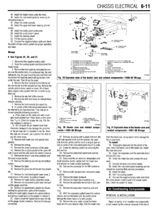 214
214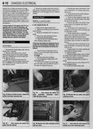 215
215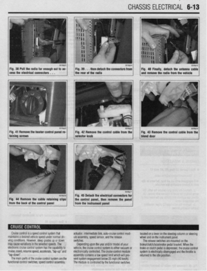 216
216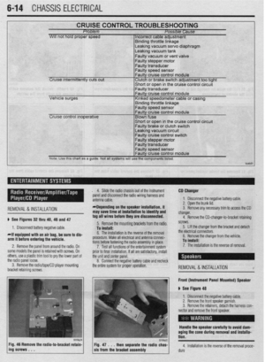 217
217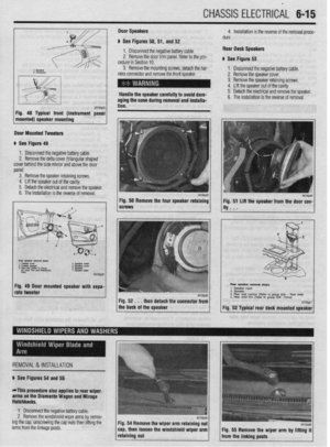 218
218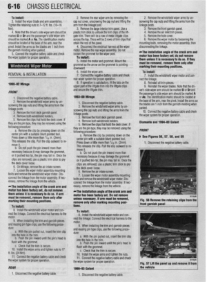 219
219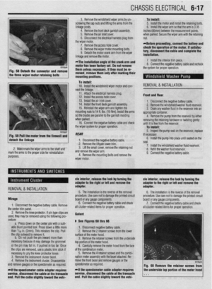 220
220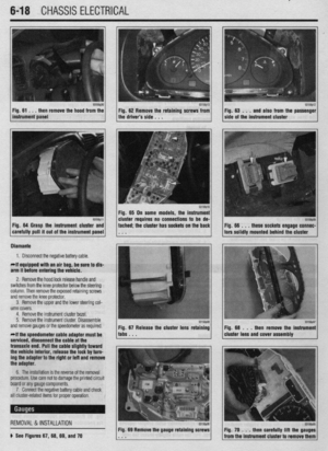 221
221 222
222 223
223 224
224 225
225 226
226 227
227 228
228 229
229 230
230 231
231 232
232 233
233 234
234 235
235 236
236 237
237 238
238 239
239 240
240 241
241 242
242 243
243 244
244 245
245 246
246 247
247 248
248 249
249 250
250 251
251 252
252 253
253 254
254 255
255 256
256 257
257 258
258 259
259 260
260 261
261 262
262 263
263 264
264 265
265 266
266 267
267 268
268 269
269 270
270 271
271 272
272 273
273 274
274 275
275 276
276 277
277 278
278 279
279 280
280 281
281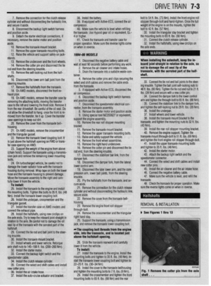 282
282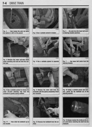 283
283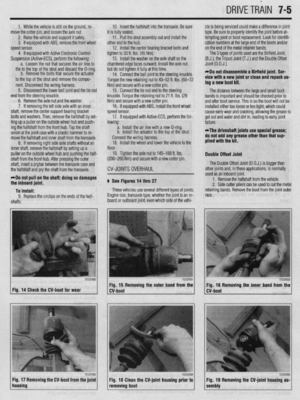 284
284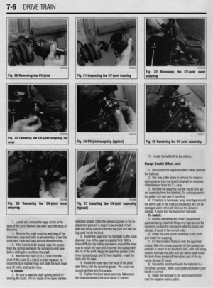 285
285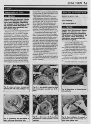 286
286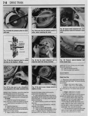 287
287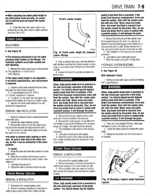 288
288 289
289 290
290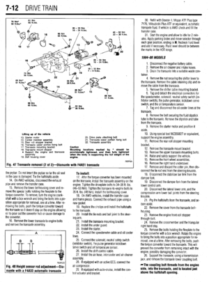 291
291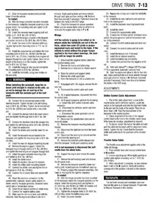 292
292 293
293 294
294 295
295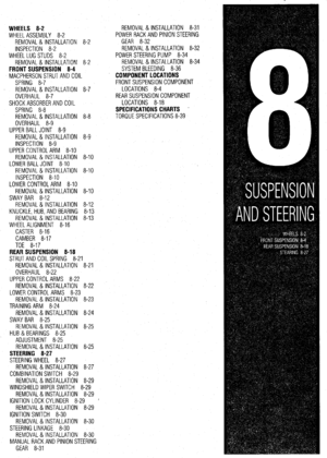 296
296 297
297 298
298 299
299 300
300 301
301 302
302 303
303 304
304 305
305 306
306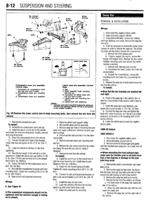 307
307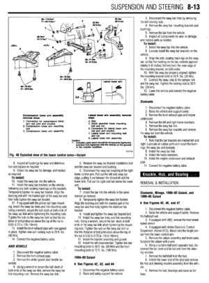 308
308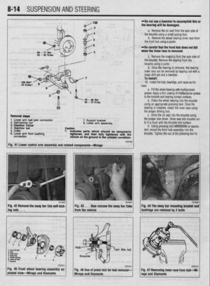 309
309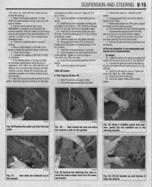 310
310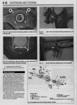 311
311 312
312 313
313 314
314 315
315 316
316 317
317 318
318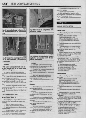 319
319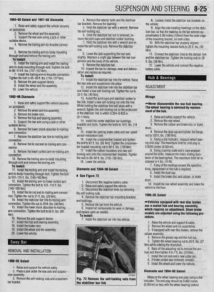 320
320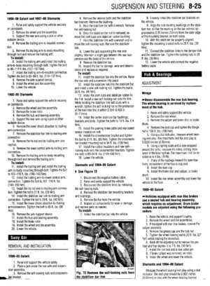 321
321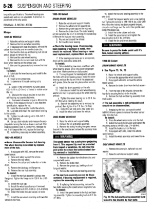 322
322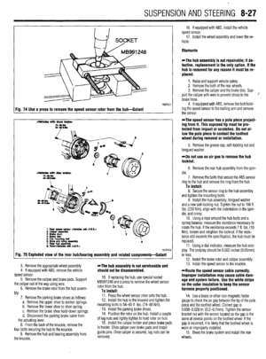 323
323 324
324 325
325 326
326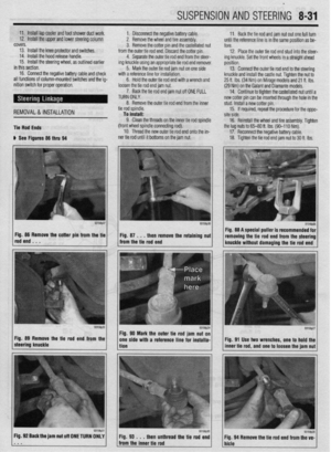 327
327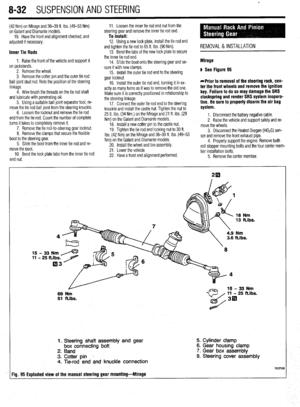 328
328 329
329 330
330 331
331 332
332 333
333 334
334 335
335 336
336 337
337 338
338 339
339 340
340 341
341 342
342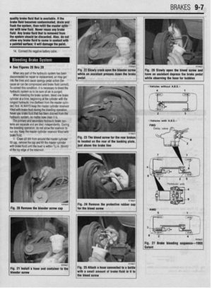 343
343 344
344 345
345 346
346 347
347 348
348 349
349 350
350 351
351 352
352 353
353 354
354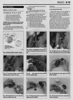 355
355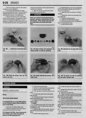 356
356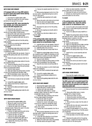 357
357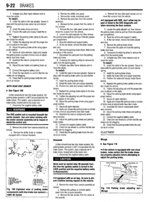 358
358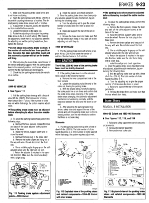 359
359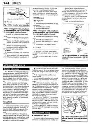 360
360 361
361 362
362 363
363 364
364 365
365 366
366 367
367 368
368 369
369 370
370 371
371 372
372 373
373 374
374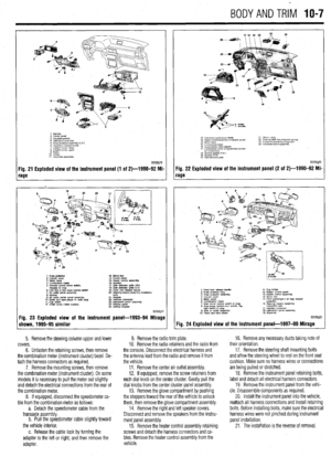 375
375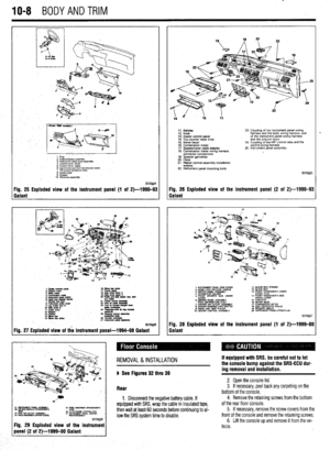 376
376 377
377 378
378 379
379 380
380 381
381 382
382 383
383 384
384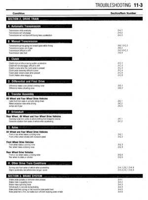 385
385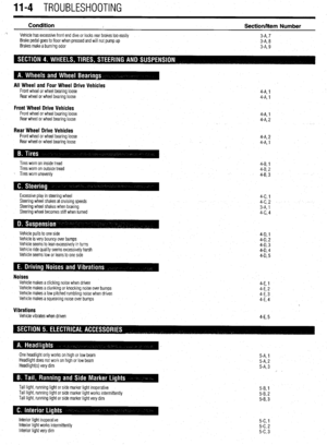 386
386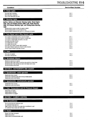 387
387 388
388 389
389 390
390 391
391 392
392 393
393 394
394 395
395 396
396 397
397 398
398 399
399 400
400 401
401 402
402 403
403 404
404 405
405 406
406 407
407