Page 17 of 408

l
1-18 GENERALINFORMATIONAND MAINTENANCE
the clamps and remove the cables, negative cable
first. On batteries with posts on top, the use of a
puller specially made for this purpose is recom-
mended. These are inexoensive and available in most alternator or turn the adjusting bolt to adjust belt ten-
sion. Once the desired value is reached, secure the
bolt or locknut and recheck tension.
d”t” lJdlL> X”lt;>. 31°C LtXlllllldl lJdllt2)’ MLJIC, dlt’ X- cured with a small bolt. ST& I REMOVAL &INSTALLATION
Clean the cable clamps and the battery terminal I
with a wire brush, until all corrosion, grease, etc., is
removed and the metal is shinv. It is esneciallv imnnr-
tant to c
knife is useful nere), since a smart
material or oxidation there will pre Clean the cable clamps and the battery terminal
with a wire brush, until all corrosion, grease, etc., is
removed and the metal is shiny. It is especially impor-
tant to clean the inside of the clamp thoroughly (an old
knife is useful here), since a small deposit of foreign
material or oxidation there will prevent a sound electri-
cal connection and inhibit either starting or charging.
Special tools are available for cleaning these parts,
one type for conventional top post batteries and an-
other type for side terminal batteries. It is also a good
idea to apply some dielectric grease to the terminal, as
this will aid in the prevention of corrosion,
After the clamps and terminals are clean, reinstall
the cables, negative cable last; DO NOT hammer the
clamps onto battery posts. Tighten the clamps se-
curely, but do not distort them. Give the clamps and
terminals a thin external coating of grease after in-
stallation, to retard corrosion.
Check the cables at the same time that the terminals
are cleaned. If the cable insulation is cracked or bro-
ken, or if the ends are frayed, the cable should be re-
placed with a new cable of the same length and gauge.
CHARGING
the cables, negative cable last; DO NOT hammer the
curely, but do not distort them. Give the clamps and
terminals a thin external coating of grease after in-
stallation, to retard corrosion.
Check the cables at the same time that the terminals
are cleaned. If the cable insulation is cracked or bro-
ken, or if the ends are frayed, the cable should be re-
placed with a new cable of the same length and aauae.
CHARGING
Fig. 62 mere are typically 3 types of ac-
cessory drive belts found on vehicles today 1. Loosen the alternator support nut.
2. Loosen the adjuster lock bolt.
3. Rotate the adjuster bolt counter clockwise to
I .I , . . . * . .
I Tn i”et*ll* Fig. 62 There are typically 3 types of ac-
Fig. 64 Deep cracks in this belt will cause
flex, building up heat that will eventually 11, 1.8L, 2.OL and 2.4L Engines
cal connection and inhibit either starting or charging.
Special tools are available for cleaning these parts,
one type for conventional top post batteries and an-
other type for side terminal batterin, I+ if QI@* 3 nnnd
idea to apply some dielectric grr
this will aid in the prevention of ,,vIIuaIUII.
After the clamps and terminals are clean, reinstall 1.5L, 1.6
AL TERNA TOR BE1 T
e See Figures 67,68, and 69
1. Loosen the alternator support nut.
2. Loosen the adjuster lock bolt.
3. Rotate the adjuster bolt counter clockwise to
release the tension on the belt.
4. Remove the belt.
To install:
5. Install the belt on the pulleys.
6. Rotate the adjuster bolt clockwise until the
proper tension is reached.
7. Tighten the adjuster lock bolt and the alternator
support nut.
POWER STEERING BELT
8 See Figures 70 and 71
1. Remove the alternator belt as described above.
2. Loosen the power steering pump adjusting
bolts.
3. Remove the power steering oumo fixed bolt on
R Rntatn the cxiillrtm hnit A&+,& until the r -r- .- .- ._.. ._ .______
7. Tighten the adjuster lock bolt and the alternator
support nut.
POWER STEERING BELT
1 ..“‘.I ““..Y...Y up II”“. ..IU. ..m.*
1 lead to belt failure V.
I
I
The chemical reaction which takes place in - 1 the rear of the bracket.
4. Rotate the pump toward the engine and remove
the belt.
all batteries generates explosive hydrogen
gas. A spark can cause the battery to explode
and splash acid. To avoid serious personal
injury, be sure there is proper ventilation and
take appropriate fire safety precautions when
connecting, disconnecting, or charging a bat-
tery and when using jumper cables. To fnstall:
5. Install the belt on the pulleys.
A battery should be charged at a slow rate to keep
the plates inside from getting too hot. However, if
some maintenance-free batteries are allowed to dis-
charge until they are almost “dead,” they may have to
be charged at a high rate to bring them back to “life.”
Always follow the charger manufacturers instructions
on charging the battery. 85 The cover of this belt ex-
Fig. is worn,
REPLACEMENT
When it becomes necessary to reolace thn haeoN
‘” yyL’“‘J’ I or oreMer
select one with an amperage rating equal tc .
a ----
than the battery originally installed. Deterioration and
just plain aging of the battery cables, starter motor,
and associated wires makes the battery’s job harder
in successive years. The slow increase in electrical
resistance over time makes it prudent to install a new
battery with a greater capacity than the old. 1 Fig. 67 Loosen the adjuster lock bolt . . .
I ‘-
I -. -_ tm1217 Fig. 66 Installing too wide a belt can resylt
in serious belt wear and/or breakage
the belt and run outward. All worn or damaged drive
belts should be replaced immediately. It is best to re-
place all drive belts at one time, as a preventive
uring this service operation. maintenance measure, d
- ADJUSTMENT : *
INSPECTION Excessive belt tension will cause damage to the al-
e See Figures 62, 83, 64, 65, and 88
Inspect the belts for signs of glazing or cracking. A
glazed belt will be perfectly smooth from slippage,
while a good belt will have a slight texture of fabric
visible. Cracks will usually start at the inner edge of pulley bearings, while, on
It tension will
Droduce slin ternator and water pump
the other hand, loose be
r ------ r
and premature wear on the belt. Therefore, be sure to
adjust the belt tension to the proper level.
To
adjust the tension ’ ’ ’ ” ’ ‘* adjusting bolt or fixing b
alternator bracket or tens on a onve Den. loosen me I Fig. 68 . . . then
from the engine remove the alternator
bolt locknut on the alternator,
iion pulley. Then move the
Page 18 of 408

GENERAL INFORMATION AND MAlNTENANdE l-19
792UQ4 Fig. 69 Accessory V-belt routing-Mii
subishf 1.6L, 1.6L,-1.6L, 2.OL and 2.4L en
gines
33151PM Fig. 70 After the adjusting and fixed bolt!
are loosened, rotate the pump . . .
/ F$71t immtl$mm&a the power ::: 6. Rotate the pump until the proper tension is
reached.
7. Tighten the adjusting bolts on the pump.
8. Tighten the fixed bolt on the rear of the bracket.
9. Install the alternator belt.
A/r: COMPRESSOIl BEL f
1. Loosen the tension oullev and remove the belt.
2. The installation is the reverse of the removal.
.3.gL DGHC, 3.OL SOHC (Gaiant models
only) and 3.5L Engines 4. Remove the belt.
To install:
5. Install the belt on the crankshaft and alternator
pulleys.
6. Using the adjusting bolt on the tensioner,
tighten the belt to the desired tension.
7. Tighten the fixing nut to hold the adjustment.
8. Install the undercover and lower the vehicle to
_,
the tloor.
9. Connect the negative battery cable.
POWER SliEERlNG BEL f
6 See Figures 72 and 73 1. Disconnect the neaative batteN cah+P
-I
Wait at least 60 seconds after the negative
battery cable is disconnected to prevent poS-
sibie deployment of the air bag.
2. Raise and safely support the vehicle and re-
mob re the undercover.
3. Remove the alternator and NC compressor
belt.
4. Lower the vehicle and remove the cruise con-
trol oumn link iW%mblV. 79244Q.37
-- I-- r ---- - _I
Fig. 72 Serpentine belt routing-Mitsubishi 5. Place the power steering hose under the oil
reservoir.
3.OL engines (except 1696-00 Galant mod-
6.
Loosen the tension pulley fixing bolts and re-
els)
Generator pulP
1 move the power steering pump drive belt.
To install:
1 7. install the Dower steerina oumu r+r+v~ hp++
8. Insert an extension bar &eoufvaik;;t”f;;id‘he
opening at the end of the tension pulley bracket and
pivot the pulley to apply tension to the belt.
9. Tighten the fixing bolts.
10. Raise the vehicle and install the alternator and
compressor belt.
Il. Install the undercover and lower +hfi vph+r+p
.I,., .VII.“.Y.
12. Connect the negative battery cable.
I 3.OL SGHC (Diamante Models Onivl Enotne
I ,r ” 1. Disconnect the negative battery cable.
2.’ Loosen the lockbolt on the face nf the A/C _ __.- tensioner pulley.
3
Turn the adiustina bolt of the A/C +fincrnner
pulley to loosen the tension of the A/C belt.
4. Remove the A/C compressor belt.
5.
Loosen the locknut on the face of the power
to loosen the tc
7. Remov
Fig. 73 Accessory V-belt routing-Mitsubishi
3.5L and 1996-00 3.OL SOHC Galant en-
gines steering/alternator tensloner pulley.
6. Turn the adjusting bolt of the tensioner pulley
msion of the belt.
‘e the power steering/alternator belt.
To install:
8. Install the power steering/alternator belt first
.* .* . ,^
ssor drive belt. ana tnen tne A/ti compre:
9. Adjust the belts t+
ing the adjusting bolts anu
II~IIWII pueey tlxmg I the proper tension by turn-
A.:-L I-..-.. I,^, .’
nut/bolt.
10. Tighten the mounting nut of the power steer-
ing/alternator tensioner pulley to 36 ft. Ibs. (50 Nm).
Wait at least 60 seconds after the negative
battery cable is disconnected to prevent pos-
sible deployment of the air bag. -The manufacturer does not provide a
torque specification for the bolt that secures
A/C tensioner pulley.
2. Raise and safely support the vehicle and re- 11. Connect the negative battery cable.
move the front undercover.
3. Loosen the tension pulley fixing nut and relieve
the tension on the belt by turning the adjusting bolt.
Page 19 of 408

.
l-20 GENERALINFORMATIONAND MAINTENANCE
INSPECTION
# See Figures 74 thru 81
All engines covered by this manual utilize timing
belts to drive the camshaft from the crankshafts turn-
ing motion and to maintain proper valve timing.
Some manufacturers schedule periodic timing belt
replacement to assure optimum engine performance,
to make sure the motorist is never stranded should
the belt break (as the engine will stop instantly) and
for some (manufacturers with interference motors) to
prevent the possibility of severe internal engine dam-
age
St10Ula the Delt break. Although the 1.5L and 1.8L engines are not listed
as an interference motors (it is not listed by the man-
ufacturer as a motor whose valves might contact the
pistons if the camshaft was rotated separately from
the crankshaft) the first 2 reasons for periodic re-
placement still apply and the timing belt should be
replaced at 60,000 miles (96,000 km). The 1.6L,
2.01,2.4L, 3.OL, and 35L engines are listed as inter-
ference motors, so the timing belt MUST be replaced
at 60,000 miles (96,000 km) to avoid severe engine
damage if the belt should break.
But whether or not you decide to replace the tim-
ing belt in the manufacturers schedule, you would be
wise to check it periodically to make sure it has not
become damaged or worn. Generally speaking, a se-
verelv worn belt mav cause enaine oerformance to
drop~dramatically, but a damaged belt (which could
give out suddenly) may not give as much warning. In
general, any time the engine timing cover(s) is (are)
removed you should inspect the belt for premature
parting, severe cracks or missing teeth. Also, an ac-
cess plug is provided in the upper portion of the tim-
ing cover so that camshaft timing can be checked
without cover removal. If timing is found to be off,
cover removal and further belt inspection or replace-
ment is necessary.
tml245 Fig. 76 look for noticeable cracks or wear
on the belt face
_
For the timing belt removal and installation proce-
dure, please refer to Section 3 of this manual. Fig. 74 Check for premature parting of the
belt
INSPECTION
. 75 Check if the teeth are cracked or
fig. 77 You may only have damage on one
side of the belt; if so, the guide could be
the culprit
b See Figures 82,8S, 84, and 85 .
Upper and lower radiator hoses, along with the
heater hoses, should be checked for deterioration,
leaks and loose hose clamps at least every 30,000
miles (48,000 km). It is also wise to check the hoses
periodically in early spring and at the beginning of
the fall or winter when you are performing other
maintenance. A quick visual inspection could dis-
cover a weakened hose which might have left you
stranded if it had remained unrepaired.
Whenever you are checking the hoses, make sure
the engine and cooling system are cold. Visually in-
spect for cracking, rotting or collapsed hoses, and w-
place as necessary. Run your hand along the length
of the hose. If a weak or swollen spot is noted when
squeezing the hose wall, the hose should be re- Fig. 78 Foreign materials can get in be- Fig. 79 Inspect the timing belt for c
tween the teeth and cause damage fraying, glazing or damage of any kind
Fig. 80 Damage on only one side of the tim-
I I Fig. 81 ALWAYS replace the timing belt at
ing belt may indicate a faulty guide
the interval specified by the manufacturer
, L placed.
Page 20 of 408

GENERALINFORMATIONAND MAINTENANCE l-21
IWSIZXJ FM. 83 A hose clamn that is taa tiaht can
Fig. 82 The cracks developing along this
hose are a result of age-related hardening caise older hoses td separate and ‘iear on
either side of the clamp
lCCS1221 Fig. 84 A soft spongy hose (identifiable by
1 the swollen section) will eventually burst
and should be replaced
IEMOVAL &,INSTALLATION '
1. Remove the radiator pressure cap. her of the sorina tension tvoe (which reouire oliers
3 squeeze the 6bs and loosenj or of the’screw ten-
ion type (which require screw or hex drivers to
oosen). Pull the clamps back on the hose away from
he connection. Never remove the pressure cap while the en-
gine is running, or personal injury from
scalding hot coolant or steam may result. If
possible, wait until the engine has cooled to
remove the pressure cap. If this is not possi-
ble, wrap a thick cloth around the pressure
cap and turn it slowly to the stop. Step back
while the pressure is released from the cool-
ing system. When you are sure all the pres-
sure has been released, use the cloth to turn
and remove the cao.
2. Position a clean container under the radiator
and/or engine draincock or plug, then open the drain
and allow the cooling system to drain to an appropri-
ate level. For some upper hoses, only a little coolant
must be drained. To remove hoses positioned lower
on the engine, such as a lower radiator hose, the en-
tire cooling system must be emptied.
When draining coolant, keep in mind that
cats and dogs are attracted by ethylene gly-
col antifreeze, and are quite likely to drink
any that is left in an uncovered container or
in puddles on the ground. This will prove fa-
tal in sufficient quantity. Always drain
coolant into a sealable container. Coolant
may be reused unless it is contaminated or
several years old. 9. Close the radiator or engine drains and prop-
erly refill the cooling system with the clean drained
engine coolant or a suitable mixture of ethylene gly-
cot coolant and water.
10. If available, install a pressure tester and check
for leaks. If a pressure tester is not available, run the
engine until normal operating temperature is reached
(allowing the system to naturally pressurize), then
check for leaks.
If you are checking for leaks with the system
at normal operating temperature, BE EX-
TREMELY CAREFUL not to touch any moving
or hot engine parts. Once temperature has
been reached. shut the enaine OFF. and
Fig. 85 Hoses are likely to deteriorate from
the inside if the cooling system is not peri-
odically flushed check for leaks around the-hose fittings and
connections which were removed earlier.
INSPECTION
b See Figures 88 and 87
The CV (Constant Velocity) boots should be
checked for damage each time the oil is changed and
any other time the vehicle is raised for service. These
boots keep water, grime, dirt and other damaging
matter from entering the CV-joints. Any of these
could cause early CV-joint failure which can be ex-
pensive to repair. Heavy grease thrown around the in-
side of the front wheel(s) and on the brake
caliper/drum can be an indication of a torn boot.
Thorouahlv check the boots for missina clamos and 3. Loosen the hose clamps at each end of the
rose requiring replacement. Clamps are usually ei-
4. Twist, pull and slide the hose off the fitting,
sking care not to damage the neck of the component
rom which the hose is being removed.
*If the hose is stuck at the connection, do
lot try to insert a screwdriver or other sharp
ool under the hose end in an eff art to free it,
IS the connection and/or hose may become
lamaged. Heater connections especially
nay be easily damaged by such a procedure.
f the hose is to be replaced, use a single-
!dged razor blade to make a slice along the
lortion of the hose which is stuck on the con-
section, perpendicular to the end of the
lose. 00 not cut deep so as to prevent dam-
aging the connection. The hose can then be
keeled from the connection and discarded. Fig. 86 CV-boots must be inspected period-
5.. Clean both hose mounting connections. In-
,pect the condition of the hose clamps and replace
hem, if necessary.
To install:
6. Dip the ends of the new hose into clean en-
fine coolant to ease installation.
7. Slide the clamps over the replacement hose,
hen slide the hose ends over the connections into
rosition.
8. Position and secure the clamps at least l/d in.
6.35mm) from the ends of the hose. Make sure they
Ire located beyond the raised bead of the connector.
Page 21 of 408
 the cooler it
your driving is long distance, high speed trave")
l-22 GENERALINFORMATIONAND MAINTENANCE
tears. If the boot is damaged, it should be replaced
trode is to the block’s cooling passages) the cooler it
your driving is long distance, high speed travel, use a
immediately. Please refer to Section 7 for procedures.
will operate. A plug that absorbs little heat and re-
colder plug; if most of your driving is stop and go,
mains too cool will quickly accumulate deposits of
use a hotter plug. Original equipment plugs are gen-
oil and carbon since it is not hot enough to burn
erally a good compromise between the 2 styles and
them off. This leads to plug fouling and consequently
most people never have the need to change their
to misfiring. A plug that absorbs too much heat will
plugs from the factory-recommended heat range.
ti See Figure 88 have no deposits but, due to the excessive heat, the
,electrodes will burn away quickly and might possibly
REMOVAL &INSTALLATION
A typical spark plug consists of a metal shell sur- lead to preignition or other ignition problems. Preig-
rounding a ceramic insulator. A metal electrode ex- nition takes place when plug tips get so hot that they
ti See Figures 90 thru 95
tends downward through the center of the insulator glow sufficiently to ignite the air/fuel mixture before
and protrudes a small distance. Located at the end of the actual spark occurs. This early ignition will usu- A set of spark plugs usually requires replacement
the plug and attached to the side of the outer metal ally cause a pinging during low speeds and heavy after about 20,000-30,000 miles (32,000-48,000
shell is the side electrode. The side electrode bends loads. km), depending on your style of driving. In normal
in at a 90” angle so that its tip is just past and paral- The general rule of thumb for choosing the correct operation plug gap increases about 0.001 in.
lel to the tio of the center electrode. The distance be- heat range when picking a spark plug is: if most of (0.025mrn) for every 2,500 miles
(4,000 km). As the
tween these two electrodes (measured in thousandths
of an inch or hundredths of a millimeter) is called the
spark piug gap.
The spark plug does not produce a spark, but in-
steed provides a gap across which the current can
arc. The coil produces anywhere from 20,000 to
50,000 volts (depending on the type and application)
which travels through the wires to the spark plugs.
The current passes along the center electrode and
jumps the gap to the side electrode, and in doing so,
ignites the air/fuel mixture in the combustion charn-
ber.
SPARKPLUG HEATRANGE
ti See Figure 89
Spark plug heat range is the ability of the plug to
dissipate heat. The longer the insulator (or the farther
INSULATOR CRACKS
OFTEN OCCUR HERE
SIDE ELECTRODE ENTER ELECTRODE:
(SEND TO ADJUST GAP) FILE FLAT WHEN
ADJUSTING GAP;
DO NOT BEND
Fig. 88 Cross-section of a spark plug
it extends into the engine), the hotter the plug will
operate; the shorter the insulator (the closer the elec- Fig. 90 Carefully twist the boot end of the
I
spark plug wire and withdraw the spark plug
wire boot from the cylinder head
Fig. 92 A locking extension such as this is
extremely helpful when removing spark
plugs that are centrally located in the cyhn-
Fig. 94 . . .
then carefully withdraw the
spark plug from the engine Fig. 91 A special spark plug socket with a
rubber insert is required to remove the
spark plugs. Typically the spark plugs
re-
quire a Ya spark plug socket
Fig, 93 Using the appropriate sized spark
plug socket, necessary extensions and drive
tools, loosen the spark plug . . .
93151ptxl Fig. 95 After removing the plug from the en-
gine, inspect it using the spark plug condi-
tion chart in this section to determine the
running condition of your engine
Page 22 of 408

t
GENERALINFORMATIONAND MAINTENANCE l-23
gap increases, the plug’s voltage requirement also in-
creases. It requires a greater voltage to jump the the spark plug counterclockwise to loosen and re-
move the spark plug from the bore.
wider gap and about &o to three times as much volt-
age to fire the plug at high speeds than at idle. The
improved air/fuel ratio control of modern fuel injec-
tion combined with the higher voltage output of mod- Be sure not to use a flexible extension on the place. The click may be felt or heard, then gently pull
ern ignition systems will often allow an engine to run socket. Use of a flexible extension may allow back on the boot to assure proper contact.
.___. . _
significantly longer on a set of standard spark plugs, a shear force to be agptf’ ea to me plug.
A 12. On the 3.OL fSOHC and DOHC) and 3.5L en-
LL_ _I___ -u I_ IL-
but keep in mind that efficiency will drop as the gap shear force could break tne pug on III me
tion 3 for the installation procedure.
widens (along with fuel economy and power). cylinder head, leading to costly and frustrat-
13. If equipped, install the center cover.
When you’re removing spark plugs, work on one ing repairs.
at a time. Don’t start by removing the plug wires all at
once, because, unless you number them, they may To install:
INSPECTION & GAPPING
11. Apply a small amount of silicone dielectric
compound to the end of the spark plug lead or inside
the spark plug boot to prevent sticking, then install
the boot to the spark plug and push until it clicks into
gines, install the upper intake manifold. Refer to Sec-
,,Y” ..1111 uy”’ 1 the neaative bat&v cable and if become mixed up. Take a minute before you begin
and number the wrrpc with +sne
1. Disconnect. ~~.~
--..-., -..-.-, -..-
thevehicle has been run recently, allow the engine to
thoroughly cool.
2. If equipped, remove the center cover.
3. On the 3.OL (SOHC and DOHC) and 3.5L en-
gines, the upper intake manifold must be removed to
access the rear spark plugs. Refer to Section 3 for the
removal procedure.
4. Carefully twist the spark plug wire boot to
loosen it, then pull upward and remove the boot from
the plug. Be sure to pull on the boot and not on the
wire, otherwise the connector located inside the boot
may become separated.
5. Using compressed air, blow any water or de-
bris from the spark plug well to assure that no harm-
ful contaminants are allowed to enter the combustion
chamber when the spark plug is removed. If com-
pressed air is not available, use a raa or a brush to must be replaced.
Check the plugs for deposits and wear, If they are 7. Inspect the spark plug boot for tears or dam-
age. If.a damaged boot is found, the spark plug wire
8. Using a wire feelergauge, check and adjust
the spark plug gap. When using a gauge, the proper
size should pass between the electrodes with a slight
drag. The next larger size should not be able to pass
while the next smaller size should pass freely.
9. Carefully thread the plug into the bore by
hand. If resistance is felt before the plug is almost
completely threaded, back the plug out and begin
threading again. In small, hard to reach areas, an old
spark plug wire and boot could be used as a thread-
ing tool. The boot will hold the plug while you twist
the end of the wire and the wire is supple enough to
twist before it would allow the plug to crossthread.
Do not use the spark plug sock?
l -- K-rrA tha nhme Alwmm rarntdlv thw GL I” IlllGa”
the possibility of crossthreading and damag- lad the plug
. ..Y f..“YY. rn”Y,‘““mY*“.‘, .I**” by hand or using an old plug wire to prevent
ing the cylinder head bore.
10. Carefully tighten the spark plug. If the plug
you are installing is equipped with a crush washer,
seat the plug, then tighten about I/, turn to crush the
washer. If you are installing a tapered seat plug,
tighten the plug to specifications provided by the ve-
hicle or plug manufacturer. b See Figures 98, 97, 98, 99, and 100
not going to be replaced, clean the plugs thoroughly.
Remember that any kind of deposit will decrease the
efficiency of the plug. Plugs can be cleaned on a
spark plug cleaning machine, which can sometimes
be found in service stations, or you can do an accept-
able job of cleaning with a stiff brush. If the plugs are’
cleaned, the electrodes must be filed flat. Use an ig-
nition points file, not an emery board or the like,
which will leave deposits. The electrodes must be
filed perfectly flat with sharp edges; rounded edges
reduce the spark plug voltage by as much as 50%.
Check spark plug gap before installation. The
ground electrode (the L-shaped one connected to the
body of the plug) must be parallel to the center elec-
trode and the specified size wire gauge (please refer
to the Tune-Up Specifications chart for details) must
pass between the electrodes with a slight drag:
*,NEVER adjust the gap on a used platinum
. clean the area.
*Remove the spark plugs when the engine
is cold, if possible, to prevent damage to the
threads. If removal of the plugs is difficult,
apply a few drops of penetrating oil or sili-
cone spray to the area around the base of the
plug, and allow it a few minutes to work.
6. Using a spark plug socket that is equipped
with a rubber insert to properly hold the plug, turn type spark plug.
Always check the gap on new plugs as they are
not always set correctly at the factory. Do not use a
flat feeler gauge when measuring the gap on a used
plug, because the reading may be inaccurate. A
round-wire type gapping tool is the best way to check
the gap. The correct gauge should pass through the
electrode gap with a slight drag. If you’re in doubt, try
one size smaller and one laraer. The smaller aauqe
Page 23 of 408

l-24 GENERALINFORMATIONAND MAINTENANCE
b%slZl2 Fig. 97 A variety of tools and gauges are
needed for spark plug service tm2903 Fig. 98 Checking the spark plug @au with a tccs2904 feeler gauge. - Fig. 99 Adjusting the spark plug gap
ig. 100 If the standard plug Is in good con-
ftlon, the electrode may be filed flat- the two ends. Take the length and multiply it by 6,000
to achieve the maximum resistance allowable in each
wire, resistance should not exceed this value. If resis-
tance does exceed this value, replace the wire.
*Whenever the high tension wires are re- ’
moved from the plugs, coil, or distributor,
silicone grease must be applied to the boot
before reconnection. Coat the entire Interior
surface with a suitable silicone grease.
REMOVAL &INSTALLATION
# See Figures 90,103 and 104
1. Remove the air cleaner inlet tube.
2. If eouiooed, remove the center cover from the
WARNING: do not file platinum plugs
valve covei.
3. Label each spark plug wire and make a note of
should go through easily, while the larger one its routing.
I’ shouldn’t go through at all. Wire gapping tools usu-
ally have a bending tool attached. Use that to adjust
the side electrode until the proper distance is ob-
tained. Absolutely never attempt to bend the center
electrode. Also, be careful not to bend the side elec- *Don’t rely on wiring diagrams or sketches
for spark plug wire routing. Improper
arrangement of spark plug wires will induce
voltage between wires, causing misfiring
and surging. Be careful to arrange spark plug
wires properly.
4. Starting with the longest wire, disconnect the
spark plug wire from the spark plug and then from
the coil pack or distributor cap.
To install:
5. If replacing the spark plug wires, match the olc
wire with an appropriately sized wire in the new set.
6. Lubricate the boots and terminals with dielec-
tric grease and install the wire on the coil pack. Make
sure the wire snaps into place.
a 7. Route the wire in the exact path as the original
nd connect the wire to the spark plug.
8. Repeat the process for each remaining wire,
iorking from the longest wire to the shortest.
9. Install the air cleaner inlet tube.
trode too far or too often as it may weaken and break
off within the engine, requiring removal of the cylin-
der head to retrieve it.
TESTING
# See Figures 191 and 102
At every tune-up/inspection, visually check the
spark plug cables for burns cuts, or breaks in the in-
sulation. Check the boots and the nipples on the dis-
tributor cap and/or coil. Replace any damaged wiring.
Every 50,000 miles (80,000 km) or 60 months, the
resistance of the wires should be checked with an
ohmmeter. Wires with excessive resistance will cause
misfiring, and may make the engine difficult to start in
damp weather.
To check resistance, an ohmmeter should be used ’
on each wire to test resistance between the end con-
nectors. Remove and install/replace the wires in or- ’
der, one-by-one.
Resistance on these wires should be 4,000-6,000
ohms per foot. To properly measure this, remove the
wires from the plugs and the coil pack. Do not pierce
any ignition wire for any reason. Measure only from Fig. 103 Remove the spark plug wires from
tcG1009 Fig. 102 Checking individual plug wire re-
sistance with a digital ohmmeter
Fig. 104 Remove the plug wires from the
wire dividers
Page 24 of 408

GENERALINFORMATIONAND MAlNTENANdE 1-25
osen the distributor cap retain-
Fig. 106. . . then remove the cap from the
distributor
Fig. 107 Grasp the rotor and pull it straight
off of the distributor shaft
REMOVAL &INSTALLATION
1. Disconnect the negative battery cable.
*Depending on the reason for removing the
distributor cap, it may make more sense to Fig. 108 The rotor must be aligned correctly
to the distributor shaft before installation
other physical damage. Make sure the distributor
cap’s center button is free of damage. Check the cap
terminals for dirt or corrosion. Always check the rotor
blade and spring closely for damage. Replace any
comoonents where damaae is found.
smmE
ALGNME
LOCATOR
b See Figures 105,106,107, and 108 GENERAL INFORMATION
b See Figures 111 and 112
Ignition timing is the measurement, in degrees of
crankshaft rotation, of the point at which the spark
plugs fire in each of the cylinders. It is measured in
degrees before or after Top Dead Center (TDC) of the
compression stroke.
Ideally, the air/fuel mixture in the cylinder will be
ignited by the spark plug just as the piston passes
I 1 COMBUSTION
ENDS 23’ ATDC
SPEED INCREASES
9ir&1$?6
Fig. 111 Advancing the ignition timing
’
CCURS
COMBUSTION
DC
ENDS 23 ATDC
3. Remove the distributor cap retaining screws or
clips and remove the cap from the distributor.
4. Note its installed position, then remove the ro-
tor from the distributor shaft. leave the spark plug wires attached. This is
handy if you are testing spark plug wires, or
if removal is necessary to access other com-
ponents, and wire length allows you to repo-
sition the cap out of the way.
2. Label and disconnect the spark plug wires
from the distributor cao.
5. The installation is the reverse of the removal.
INSPECTION
u See Figures 109 and 110
9mg27
After removing the distributor cap and rotor, clean
the components (both inside and outside of the cap)
using soap and water. If compressed air is available,
carefully dry the components (wearing safety gog-
gles) or allow the parts to air dry. You can dry them
with a clean, soft cloth, but don’t leave any lint or
moisture behind.
Once the cap and rotor have been thoroughly Inspection points for the dis Fig. 112 Retarding the tgnttion timing
cleaned, check for cracks, carbon tracks, burns or
 1
1 2
2 3
3 4
4 5
5 6
6 7
7 8
8 9
9 10
10 11
11 12
12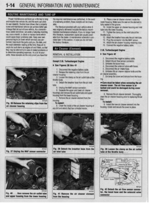 13
13 14
14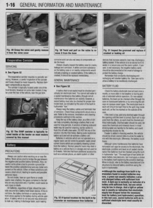 15
15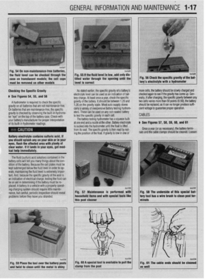 16
16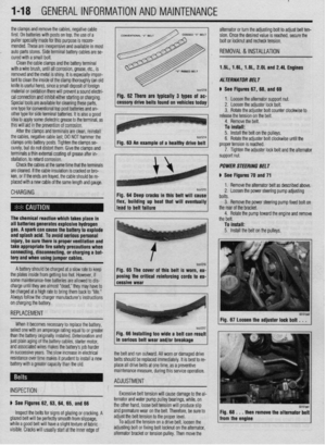 17
17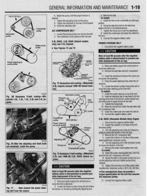 18
18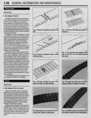 19
19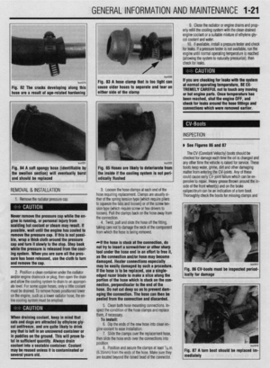 20
20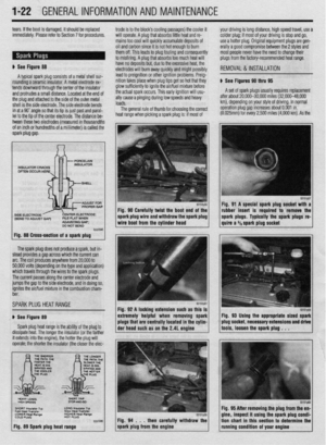 21
21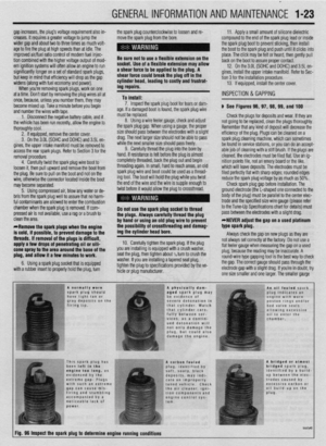 22
22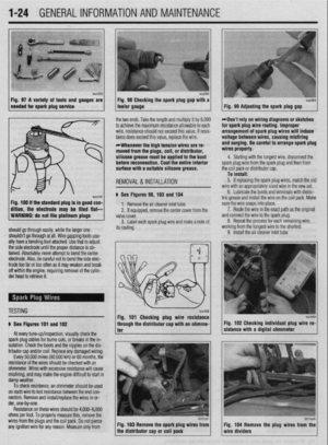 23
23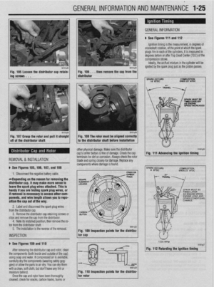 24
24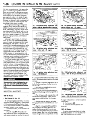 25
25 26
26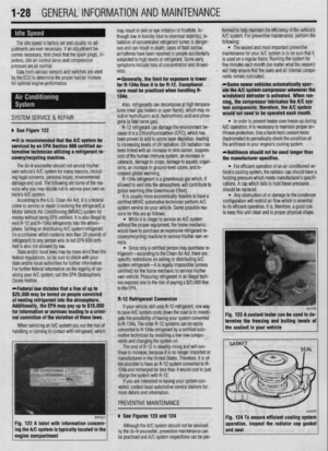 27
27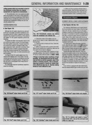 28
28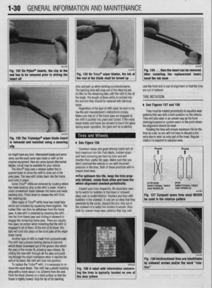 29
29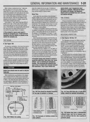 30
30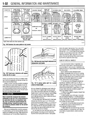 31
31 32
32 33
33 34
34 35
35 36
36 37
37 38
38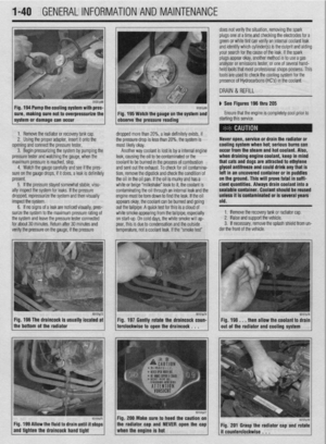 39
39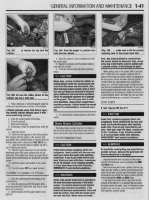 40
40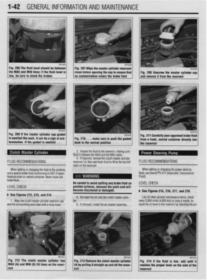 41
41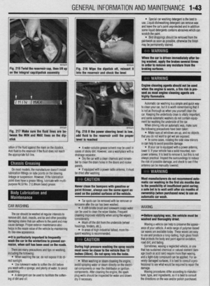 42
42 43
43 44
44 45
45 46
46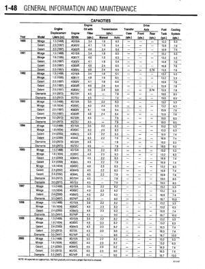 47
47 48
48 49
49 50
50 51
51 52
52 53
53 54
54 55
55 56
56 57
57 58
58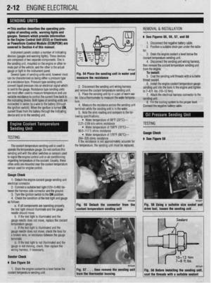 59
59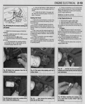 60
60 61
61 62
62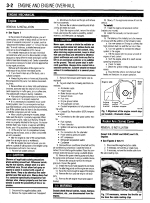 63
63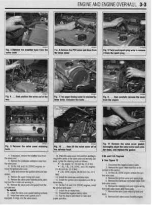 64
64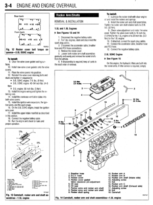 65
65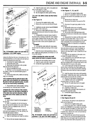 66
66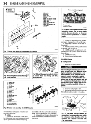 67
67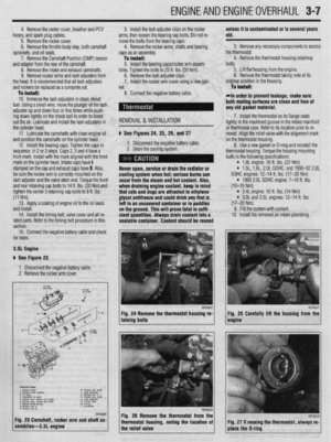 68
68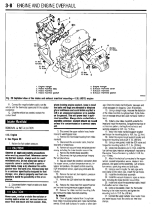 69
69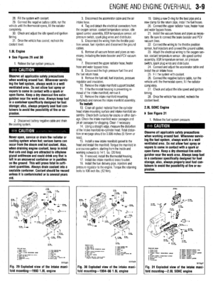 70
70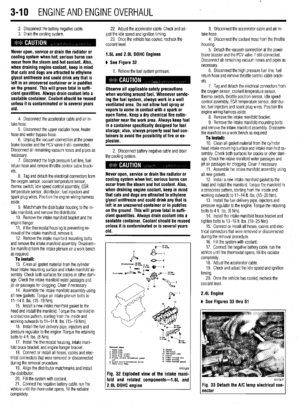 71
71 72
72 73
73 74
74 75
75 76
76 77
77 78
78 79
79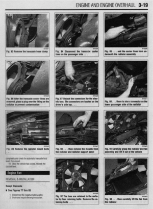 80
80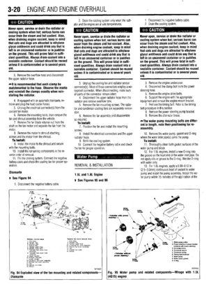 81
81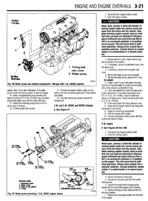 82
82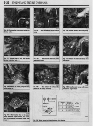 83
83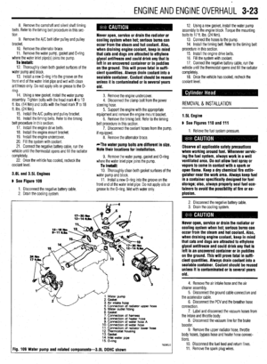 84
84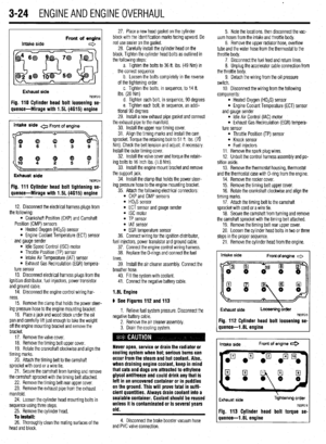 85
85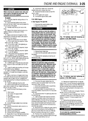 86
86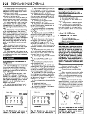 87
87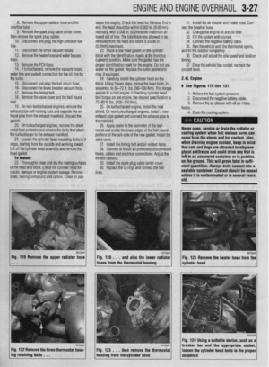 88
88 89
89 90
90 91
91 92
92 93
93 94
94 95
95 96
96 97
97 98
98 99
99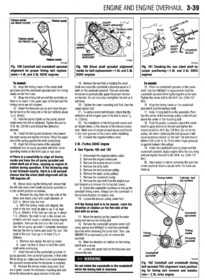 100
100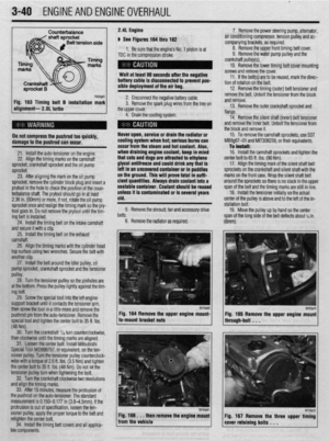 101
101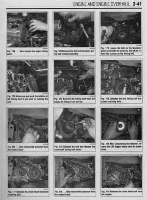 102
102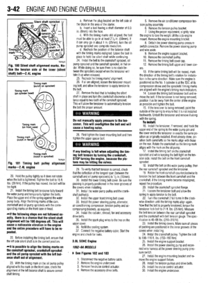 103
103 104
104 105
105 106
106 107
107 108
108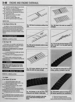 109
109 110
110 111
111 112
112 113
113 114
114 115
115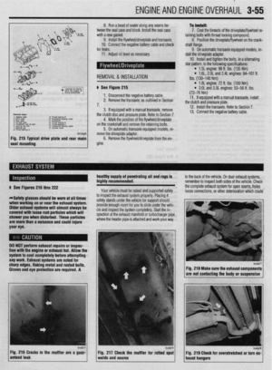 116
116 117
117 118
118 119
119 120
120 121
121 122
122 123
123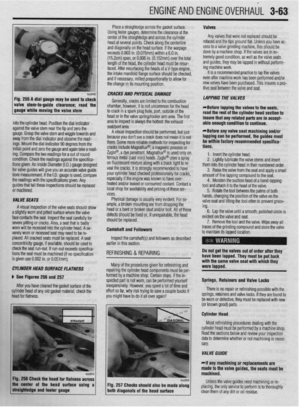 124
124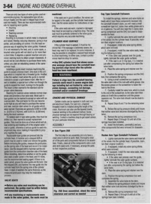 125
125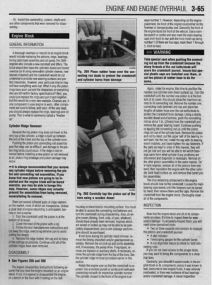 126
126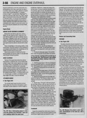 127
127 128
128 129
129 130
130 131
131 132
132 133
133 134
134 135
135 136
136 137
137 138
138 139
139 140
140 141
141 142
142 143
143 144
144 145
145 146
146 147
147 148
148 149
149 150
150 151
151 152
152 153
153 154
154 155
155 156
156 157
157 158
158 159
159 160
160 161
161 162
162 163
163 164
164 165
165 166
166 167
167 168
168 169
169 170
170 171
171 172
172 173
173 174
174 175
175 176
176 177
177 178
178 179
179 180
180 181
181 182
182 183
183 184
184 185
185 186
186 187
187 188
188 189
189 190
190 191
191 192
192 193
193 194
194 195
195 196
196 197
197 198
198 199
199 200
200 201
201 202
202 203
203 204
204 205
205 206
206 207
207 208
208 209
209 210
210 211
211 212
212 213
213 214
214 215
215 216
216 217
217 218
218 219
219 220
220 221
221 222
222 223
223 224
224 225
225 226
226 227
227 228
228 229
229 230
230 231
231 232
232 233
233 234
234 235
235 236
236 237
237 238
238 239
239 240
240 241
241 242
242 243
243 244
244 245
245 246
246 247
247 248
248 249
249 250
250 251
251 252
252 253
253 254
254 255
255 256
256 257
257 258
258 259
259 260
260 261
261 262
262 263
263 264
264 265
265 266
266 267
267 268
268 269
269 270
270 271
271 272
272 273
273 274
274 275
275 276
276 277
277 278
278 279
279 280
280 281
281 282
282 283
283 284
284 285
285 286
286 287
287 288
288 289
289 290
290 291
291 292
292 293
293 294
294 295
295 296
296 297
297 298
298 299
299 300
300 301
301 302
302 303
303 304
304 305
305 306
306 307
307 308
308 309
309 310
310 311
311 312
312 313
313 314
314 315
315 316
316 317
317 318
318 319
319 320
320 321
321 322
322 323
323 324
324 325
325 326
326 327
327 328
328 329
329 330
330 331
331 332
332 333
333 334
334 335
335 336
336 337
337 338
338 339
339 340
340 341
341 342
342 343
343 344
344 345
345 346
346 347
347 348
348 349
349 350
350 351
351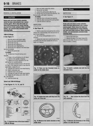 352
352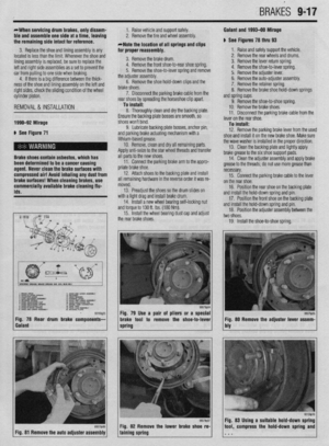 353
353 354
354 355
355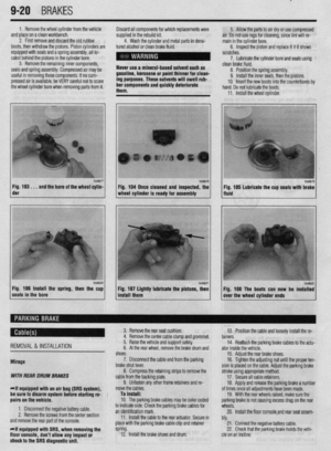 356
356 357
357 358
358 359
359 360
360 361
361 362
362 363
363 364
364 365
365 366
366 367
367 368
368 369
369 370
370 371
371 372
372 373
373 374
374 375
375 376
376 377
377 378
378 379
379 380
380 381
381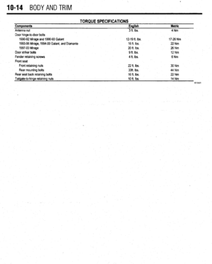 382
382 383
383 384
384 385
385 386
386 387
387 388
388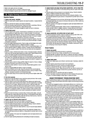 389
389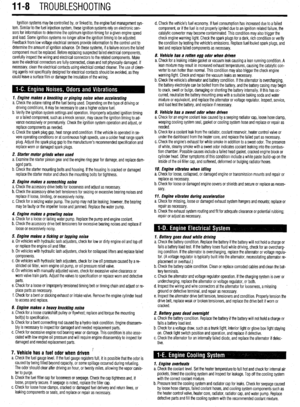 390
390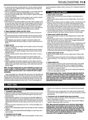 391
391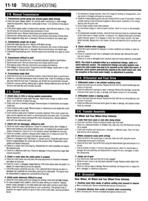 392
392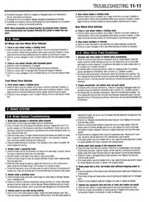 393
393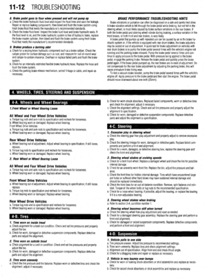 394
394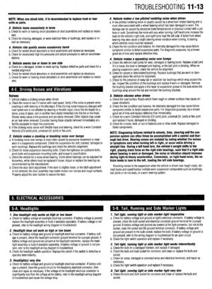 395
395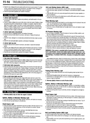 396
396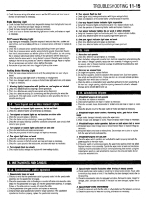 397
397 398
398 399
399 400
400 401
401 402
402 403
403 404
404 405
405 406
406 407
407