Page 97 of 408

3-36 ENGINEANDENGINEOVERHAUL
The EPA warns that urolonaed contact with
used engine oil may causeŌĆØa number of skin
disorders, including cancer! You should
make every effort to minimize your exposure
to
used engine oil. Protective gloves should
be worn when changing the oil. Wash your
hands and any other exposed skin areas as
soon as possible after exposure to
used en-
gine oil. Soap and water, or waterless hand
cleaner should be used.
4. Remove the solash shield from the wheel
93153p65 93153p60 well.
5. Remove the oil filter adapter.
6. Remove the lower and upper oil pans.
7. Remove the lower baffle, oil pump pick-up
and upper baffle.
8. Remove the oil pump case mounting bolts
and the oil pump case.
9. Remove the oil pump gear cover.
10. Make matchmarks on the oil pump rotors be-
fore removing them.
,,. r.-- -IL- -.( -L.11---ŌĆśI --. IL- -.I _ --
nemove me cranksnarr sear rrom me 011 pump
case.
To instell:
12. Install a new crankshaft seal in the oil pump
cover.
13. Apply engine oil to the rotors, then align the
matchmarks and install the rotors in the oil pump Fig. 153 Remove the fasteners, then re-
move the side inner fender splash shield
3. Raise and support the vehicle.
4. Remove the passenger side front wheel.
5. Remove the passenger side inner fender
splash shield to gain access to the crankshaft
damper.
6. On the 1.5L, 1.6L, 2.OL and 2.4L engines, re-
move the oullev-to-sorocket bolts.
7. On thei .5L, i .8L, 3.OL and 3.5L engines, re-
move the crankshaft pulley center retaining bolt.
8. Remove the damper from the crankshaft us
ing a suitable puller.
-la install:
9. Place the damper onto the crankshaft, ensur-
ing the key-way is aligned.
10. On the 1.5L, 1.8L, 3.OL and 3.5L engines, in-
e crankshaft pulley center retaining bolt and
the bolt as follows: Fig. 154 Unfasten the crankshaft pulley re-
talning bolts, then remove the pulley
case.
14. Install the rotor cover. Tighten the bolts to 7
ft. Ibs. (10 Nm).
15. Apply a 0.113 in. (3mm) bead of sealant to
the back of the oil pump case. I[ -ŌĆś-ŌĆśI IL -~-- IL-
nsrall me ca
se on me engine and tighten the bolts to IOft Ihc 11 ,,, -. , .4 Nm).
16. Install the upper baffle r tlal te and oil pump
pick-up using a new gasket. Tic fhtti,, ,,lG va,,,ti ŌĆ£ŌĆ£a,., an tha hafflc, hnltc to 7 ft. Ibs. (10 Nm) and the pit k-up bolts to 13 ft.
Ibs. (18 Nm).
17. Install the lower baffle in the upper oil pan.
Tighten the bolts to 8 ft. Ibs. (11 Nm).
18. Install the oil pans.
19. Install the oil filter adapter using a new gas-
ket. Tighten the larger bolt to 30 ft. Ibs. (41 Nm) and
the smaller bolt to 1ŌĆÖ u ŌĆśL- Inn ŌĆśI--ŌĆÖ stall thl
tighten
4
) 1.5L engine: 51-72 ft. Ibs. (70-100 Nm)
l 1.8L and 3.5L engines: 134 ft. Ibs. (185
NM
l 3.OL engines: 108-116 ft. lbs. (150-160 NW 11. On the 1.5L, 1.6L, 2.OL and 2.4L engines, in-
stall the pulley-to-sprocket bolts and tighten the bolts
as follows:
l 1.5L engine: 10 ft. Ibs. (14 Nm)
* 1.6L and 2.OL engines: 14-22 ft. Ibs. 1. Disconnect the negative battery cable.
2. Remove the engine under cover.
3. Raise and safely support the weight of the en-
gine using the appropriate equipment. Remove the
front engine mount bracket and accessory drive belts.
4. If necessary, remove the coolant reservoir
tank.
5. Using the proper equipment, slightly raise
ets, water pump pulley
7. Remove all attr
upper and lower timin{
8. Make a mark o
indicating the directior
assembled in the same the engine to take the weight off the side engine
mount. Remove the engine mount bracket.
6. Remove the drive belts, tension pulley brack-
and crankshaft pulley.
aching screws and remove the
J belt covers.
n the back of the timing belt
I of rotation so it may be re-
! direction if it is to be reused.
tensioner and remove the tim-
Loosen the timing belt
ing belt.
*If coolant or engine oil comes in contact
with the timing bplt thaw will r(mcti~~llv Wll L, .,,s,, n,,, u,uu.,vu,,,
shorten its life. A ,IS o, do not allow engine oil
#.I nn..lrŌĆØ* In rind In,
ŌĆ£I IruuI(IIIL Lu Irulll&t the timing belt sprock-
ets or tensioner assembly.
9. Remove the tensioner spacer, tensioner
spring and tensioner assembly.
cracks on back sur-
;eoarated canvas.
20. Install the tilllIllY uljllOllu IclllallllllY ~ullIPV-
:
nents. Refer to the timing belt procedure in this sec-
: tion.
21. Fill the engine with the correct amount of oil.
I . (20-30 Nm)
l 2.4L engine: 18 ft. Ibs. (25 Nm)
12. On the 1.6L and 2.OL engines, install the pul-
ley-to-sprocket bolts and tighten them to 14-22 ft.
Ibs. (20-30 Nm).
13. Install the splash shield.
14. Install the wheel, then carefully lower the ve- 10. Inspect the timing belt for I
face, sides, bottom and check for ! (
Check the tensioner pulley for smooth rotation.
To install:
11. Position the tensioner, tensioner spring and
tensioner spacer on engine block.
12. Align the timing marks on the camshaft
ft sprocket. This will position
tn the comoression stroke.
I hicle.
sprocket and cranksha
15. Install the accessory drive belts. Refer to Sec-
No. 1 piston on TDC o
Operating the engine without the proper tion 1.
13. Position the timing belt on the crankshaft
amount and type of engine oil will result in 16. Connect the negative battery cable.
sprocket and keeping the tension side of the bolt
severe engine damage.
-
22. -s
Chrmxt the nenntive h;lttm cnhle --, , IŌĆØ ,.-J XL.._ I -..-., --I.-.
23. Start the engine and check for leaks.
REMOVAL &INSTALLATION
tight, set it on the cam, shaft sprocket.
14. Apply counterc Yockwise force to the camshaft
snrnckd tn nive tensin In -r .__.._. ._ J..- ._ - _ to the belt and make sure all
timing marks are aligned.
15. Loosen the pivot side tensioner bolt and the
clnt
&In hnlt Allnur thn rnrinn tn tdm III-I thn slack, cl then , d I, IŌĆÖ r),ŌĆ£I 44ŌĆØŌĆØ ŌĆ£ŌĆ£IL. ŌĆ£llŌĆØsl LllU .yŌĆØŌĆ£yj LŌĆØ LŌĆØI\U Low UlŌĆØ L .-Refer to Section 1 for the proper timing 16. Tighten the slot side tensioner bolt ark
., , , , ,, ,, ,, , , , , ,, . ,, ,~
REMOVAL &INSTALLATION
6 See Figures 153 and 154
1. Disconnect the negative battery cable.
2. Remove the accessory drive belts from
around the crankshaft pulley. Refer to Section 1. belt service interval.
1.5L Engine
1999-94 MODELS
b See Figures 155 and 156 me p~vor sloe DOI~. IT me p~vor sloe OOII
IS ogntened
first, the tensioner could turn with bolt, causing over
tension.
17. Turn the crankshaft clockwise. Loosen the
pivot side tensioner bolt and then the slot side bolt to
allow the spring to take up any remaining slack.
Page 98 of 408

ENGINEANDENGINEOVERHAUL 3-37
1. Ben
2. Power4teerlna Dump 7. washer
8. Crankshaft pullet
9. Damper pulls
10. upper ccwer
11. Lowercowr
12. llmingbeil
13. crsnkshat? E#ocket 14. Flsnge
i 5. Tensbner spacer
16. Tef~kner WkW
1; Tgibnrr
19: camehan sprocket
91251ga
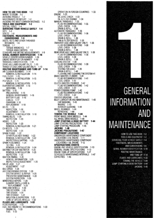
Fig. 155 Exploded view of the timing belt covers, timing belt and related parts-1990-94 1.51
engine
Fig. 156 Camshaft and crankshaft sprocket mark alignment for proper timing belt installa-
tion-1990-94 1.51 engine
Tighten the slot bolt and then the pivot side bolt to
14-20 ft. Ibs. (20-27 Nm).
18. Check the belt tension by holding the ten-
sioner and timing belt together by hand and give the
belt a slight thumb pressure at a point level with ten-
sioner center. Make sure the belt cog crest comes as
deep as about l/4 of the width of the slot side ten-
sioner bolt head. Do not manually overtighten the
belt or it will make a howling noise.
19. Install the timing belt covers and all related
items. 1995-00 MOOFLS
) See Figure 157
1. Disconnect the negative battery cable.
2. Remove the engine undercover.
3. Rotate the crankshaft clockwlse and position
the engine at TDC of the compression stroke.
4. Raise and safely support the weight of the en-
gine using the appropriate equipment. Remove the
A/C clamp, front engine mount bracket and accessory
drive belts.
20. Connect the negative battery cable.
5. Remove the crankshaft pulley. 6. Remove timing belt upper and lower covers.
7. Make a mark on the back of the timing belt
indicating the direction of rotation so it may be re-
assembled in the same direction if it is to be reused.
Loosen the timing belt tensioner and move the ten-
sioner to provide slack to the timing belt. Tighten the
tensioner in this position.
8. Remove the timing belt.
Coolant and engine oil will damage the rub-
ber in the timing belt, drastically reducing its
life. Do not allow engine oil or coolant to
contact the timing belt, the sprockets or ten-
sioner assembly.
9. If defective, remove the tensioner spacer, ten-
sioner spring and tensioner assembly.
To install: 10. Position the tensioner, tensioner spring and
tensioner spacer on engine block.
11. Align the timing marks on the camshaft
sprocket and crankshaft sprocket. This will position
No. 1 piston on TDC on the compression stroke.
12. Position the timing belt on the crankshaft
sprocket and keeping the tension side of the belt
tight, set it on the camshaft sprocket, then the ten-
sioner.
13. Apply slight counterclockwise force to the
camshaft sprocket to give tension to the belt and be
sure all timing marks are aligned.
14. Loosen the pivot side tensioner bolt and the
slot side bolt. Allow the spring to remove the slack.
15. Tighten the slot side tensioner bolt, then the
pivot side bolt. If the pivot side bolt is tightened first,
the tensioner could turn with bolt, causing over ten-
sion.
16. Turn the crankshaft clockwise. Loosen the
pivot side tensioner bolt, then the slot side bolt to al-
low the spring to take up any remaining slack.
Tighten the slot bolt, then the pivot side bolt to 17 ft.
Ibs. (24 Nm).
17. Install the timing belt covers and tighten the
cover bolts to 84-96 inch Ibs. (E-11 Nm). Install all
other applicable components.
liming mark
ming mark
Timing mark
Timing mark
Crankshaft sprocket
79235g5t Fig. 157 Align the timing belt sprockets as
indicated before removing the timing belt-
1995-00 1.51 engine
Page 99 of 408
 DOHC Engines
g See Figure 158
*The 1.6L engine is not equipped with
silent shafts. Disregard all instructions per-
taining to silent shafts if")
3-38 ENGINEANDENGINEOVERHAUL
1.61&? 2.OL (Non-Turbo) DOHC Engines
g See Figure 158
*The 1.6L engine is not equipped with
silent shafts. Disregard all instructions per-
taining to silent shafts if working on that en-
gine.
1. Disconnect the negative battery cable.
2. Remove the engine undercover.
3. If necessary, remove the coolant reservoir.
4. Using the proper equipment, slightly raise
the engine to take the weight off the side engine
mount. Remove the engine mount bracket.
5. Remove the drive belts, tension pulley brack-
ets, water pump pulley and crankshaft pulley.
6. Remove all attaching screws and remove the
upper and lower timing belt covers.
7. Rotate the crankshaft clockwise and align the
timing marks so No. 1 piston will be at TDC of the
compression stroke. At this time the timing marks on
the camshaft sprocket and the upper surface of the
cylinder head should coincide, and the dowel pin of
the camshaft sprocket should be at the upper side.
*Always rotate the crankshaft in a clockwise
direction. Make a mark on the back of the
timing belt indicating the direction of rotation
so it may be reassembled in the same direc-
tion if it is to be reused.
8. Remove the auto tensioner and remove the
outermost timing belt.
9. Remove the timing belt tensioner pulley, ten-
sioner arm, idler pulley, oil pump sprocket, special
washer, flange and spacer.
10. Remove the silent shaft (inner) belt tensioner
and remove the belt.
To install: 11. Align the timing marks on the crankshaft
sprocket and the silent shaft sprocket. Fit the inner
timing belt over the crankshaft and silent shaft
sprocket. Ensure that there is no slack in the belt.
12. While holding the inner timing belt tensioner
with your fingers, adjust the timing belt tension by
applying a force towards the center of the belt, until
the tension side of the belt is taut. Tighten the ten-
sioner bolt.
*When tightening the bolt of the tensioner,
ensure that the tensioner pulley shaft does
not rotate with the bolt. Allowing it to rotate
with the bolt can cause excessive tension on
the belt.
13. Check belt for proper tension by depressing
the belt on itŌĆÖs long side with your finger and noting
the belt deflection. The desired reading is 0.20-0.28
in. (5-7mm). If tension is not correct, readjust and
check belt deflection.
14. Install the flange, crankshaft and washer to
the crankshaft. The flange on the crankshaft sprocket
must be installed towards the inner trming belt
sprocket. Tighten bolt to 80-94 ft. Ibs. (110-130
Nm).
15. To install the oil pump sprocket, insert a
Phillips screwdriver with a shaft 0.31 in. (8mm) in di-
ameter into the plug hole in the left side of the cylin-
der block to hold the left silent shaft. Tighten the nut
to 36-43 ft. Ibs. (50-60 Nm).
16. Using a wrench, hold the camshaft at itŌĆÖs
hexagon between journal No. 2 and 3, then tighten
the bolt to 58-72 ft. Ibs. (80-100 Nm). If no hexagon
is present between journal No. 2 and 3, hold the
sprocket stationary with a spanner wrench while
tightening the retainer bolt.
17. Carefully push the auto tensioner rod in until
the set hole in the rod aligns with the hole in the
cylinder. Place a wire into the hole to retain the rod.
18. Install the tensioner pulley onto the tensioner
arm. Locate the pinhole in the tensioner pulley shaft
to the left of the center bolt. Then, tighten the center
bolt finger-tight.
19. When installing the timing belt, turn the 2
camshaft sprockets so their dowel pins are located on
top. Align the timing marks facing each other with the
top surface of the cylinder head. When you let go of
the exhaust camshaft sprocket, it will rotate 1 tooth in
the counterclockwise direction. This should be taken
into account when installing the timing belts on the
sprocket.
*Both camshaft sprockets are used for the
intake and exhaust camshafts and are pro-
vided with 2 timing marks. When the
sprocket is mounted on the exhaust
camshaft, use the timing mark on the right
with the dowel pin hole on top. For the intake
camshafl sprocket, use the 1 on the left with
the dowel pin hole on top.
20. Align the crankshaft sprocket and oil pump
sprocket timing marks.
21. After alignment of the oil pump sprocket tim-
ing marks, remove the plug on the cylinder block and
insert a Phillips screwdriver with a shaft diameter of
0.31 in. (8mm) through the hole. If the shaft can be
inserted 2.4 in. deep, the silent shaft is in the correct
position. If the shaft of the tool can only be inserted
0.61 .O in. (2C-25mm) deep, turn the oil pump
sprocket 1 turn and realign the marks. Reinsert the
tool making sure it is inserted 2.4 in. deep. Keep the
tool inserted in hole for the remainder of this proce-
dure.
*The above step assures that the oil pump
socket is in correct orientation to the silent
shafts. This step must not be skipped or a vi-
bration may develop during engine opera-
tion.
22. Install the timing belt as follows:
a. Install the timing belt around the intake
camshaft sprocket and retain it with 2 spring
clips or binder clips.
b. Install the timing belt around the exhaust
sprocket, aligning the timing marks with the
cylinder head top surface using 2 wrenches. Re-
tain the belt with 2 spring clips. c. Install the timing belt around the idler pul-
ley, oil pump sprocket, crankshaft sprocket and
the tensioner pulley. Remove the 2 spring clips.
d. Lift upward on the tensioner pulley in a
clockwise direction and tighten the center bolt.
Make sure all timing marks are aligned.
e. Rotate the crankshaft ŌĆś14 turn counterclock-
wise. Then, turn in clockwise until the timing
marks are alrgned again.
23. To adjust the timing (outer) belt, turn the
crankshaft ŌĆś14 turn counterclockwise, then turn it
clockwise to move No. 1 cylinder to TDC.
24. Loosen the center bolt. Using tool
MD998738 or equivalent and a torque wrench, apply
a torque of 22-25 inch. Ibs. (2.6-2.8 Nm). Tighten
the center bolt.
25. Screw the special tool into the engine left
support bracket until its end makes contact with the
tensioner arm. At this point, screw the special tool in
some more and remove the set wire attached to the
auto tensioner, if the wire was not previously re-
moved. Then remove the specral tool.
26. Rotate the crankshaft 2 complete turns clock-
wise and let it sit for approximately 15 minutes. Then,
measure the auto tensioner protrusion (the distance
between the tensioner arm and auto tensioner body)
to ensure that it is within 0.15-0.18 in. (3.8-4.5mm).
If out of specification, repeat Step l-4 until the spec-
ified value is obtained.
27. If the timing belt tension adjustment is being
performed with the engine mounted in the vehicle,
and clearance between the tensioner arm and the auto
tensioner body cannot be measured, the following al-
ternative method can be used:
a. Screw in special tool MD998738 or equiv-
alent, until its end makes contact with the ten-
sioner arm.
b. After the special tool makes contact with
the arm, screw it in some more to retract the auto
tensioner pushrod while counting the number of
turns the tool makes until the tensioner arm is
brought into contact with the auto tensioner
body. Make sure the number of turns the special
tool makes conforms with the standard value of
21/a-3 turns.
c. Install the rubber plug to the timing belt
rear cover.
28. Install the timing belt covers and all related
items.
29. Connect the negative battery cable.
1.8L & 2.OL SOHC Engines
g See Figures 159, 160, and 161
1. Position the engine so the No. 1 piston is at
TDC of the compression stroke.
2. Disconnect the negative battery cable.
3. Remove the engine undercover.
4. Using the proper equipment, slightly raise
the engine to take the weight off the side engine
mount. Remove the engine mount bracket.
5. Remove the drive belts, tension pulley brack-
ets, water pump pulley and crankshaft pulley.
6. Remove all attaching screws and remove the
upper and lower timing belt covers.
7. Remove the timing belt covers.
8. Remove the outer crankshaft sprocket and
flange.
9. Remove the silent shaft (inner) belt tensioner
and remove the belt.
Page 100 of 408

.
ENGlNEANDENGlliEOVERHAUL 3-39
To install: IO. Align the timing marks of the silent shaft
sprockets and the crankshaft sprocket with the timing
marks on the front case.
11. Wrap the timing belt around the sprockets so
there is no slack in the upper span of the belt and the
timing marks are still aligned.
12. Install the tensioner pulley and move the pul-
ley by hand so the long side of the belt deflects about
l/d in. (6mm).
13. Hold the pulley tightly so the pulley cannot
rotate when the bolt is tightened. Tighten the bolt to
15 ft. Ibs. (20 Nm) and recheck the deflection
amount.
14. Install the timing belt tensioner fully toward
the water pump and tighten the bolts. Place the upper
end of the spring against the water pump body.
15. Align the timing marks of the camshaft,
crankshaft and oil pump sprockets with their corre-
sponding marks on the front case or rear cover.
*There is a possibility to align all timing
marks and have the oil pump sprocket and
silent shaft out of time, causing an engine vi-
bration during operation. If the following step
is not followed exactly, there is a 50 percent
chance that the silent shaft alignment will be
180 degrees off.
16. Before installing the timing belt, ensure that
the left side (rear) silent shaft (oil pump sprocket) is
in the correct position as follows:
a. Remove the plug from the rear side of the
block and insert a tool with shaft diameter of
0.31 in. (8mm) into the hole.
b. With the timing marks still aligned, the
shaft of the tool must be able to go in at least
2ŌĆÖ13 in. (59mm). If the tool can only go in about
1 in. (25mm), the shaft is not in the correct ori-
entation and will cause a vibration during engine
operation. Remove the tool from the hole and
turn the oil pump sprocket 1 complete revolution.
Realign the timing marks and insert the tool. The
shaft of the tool must go in at least 21/3 in.
(59mm).
c. Recheck and realign the timing marks.
d. Leave the tool in place to hold the silent
shaft while continuing
17. Install the belt to the crankshaft sprocket, oil
pump sprocket, then camshaft sprocket, in that order.
While doing so, make sure there is no slack between
the sprocket except where the tensioner is installed.
18. Recheck the timing marksŌĆÖalignment. If all
are aligned, loosen the tensioner mounting bolt and
allow the tensioner to apply tension to the belt.
E
91251gbl
Fig. 180 Silent shaft sprocket alignment
marks for belt replacement-l.81 and 2.OL
SOHC engines
19. Remove the tool that is holding the silent
shaft and rotate the crankshaft a distance equal to 2
teeth on the camshaft sprocket. This will allow the
tensioner to automatically apply the proper tension
on the belt. Do not manually overtighten the belt or it
will howl.
20. Tighten the lower mounting bolt first, then the
upper spacer bolt.
21. To verify correct belt tension, check that the
deflection at the longest span of the belt is about 1/2
in. (13mm).
22. The installation of the timing belt covers and
all related items, is the reverse of the removal proce-
dure. Make sure all pieces of packing are positioned
in the inner grooves of the covers when installing.
23. Connect the negative battery cable.
2.OL (Turbo) OOHC Engine
ti See Figures 162 and 163
1. Disconnect the negative battery cable.
2. Remove the engine undercover.
3. Remove the engine mount bracket.
4. Remove the drive belts.
5. Remove the belt tensioner pulley.
6. Remove the water pump pulleys.
7. Remove the crankshaft pulley.
8. Remove the stud bolt from the engine sup-
port bracket and remove the timing belt covers.
9. Rotate the crankshaft clockwise to line up the
camshaft timing marks. Always turn the crankshaft in
the normal direction of rotation only.
10. Loosen the tension pulley center bolt.
*If the timing belt is to be reused, mark the
direction of rotation on the flat side of the
belt with an arrow.
11. Move the tension pulley towards the water
pump and remove the timing belt.
12. Remove the crankshaft sprocket center bolt
using special tool MB9g67 to hold the crankshaft
sprocket while removing the center bolt. Then, use
MB998778 or equivalent puller to remove the
sprocket.
13. Mark the direction of rotation on the timing
belt B with a arrow.
14. Loosen the center bolt on the tensioner and
remove the belt.
00 not rotate the camshafts or the crankshafl
while the timing belt is removed.
/--- PLUG
91251gb2 Fig. 161 Checking the rear silent shafl for
jroper positioning-1.8L and 2.OL SOHC
Pnoines
To Install:
15. Place the crankshaft sprocket on the crank-
shaft. Use tool MB9g67 or equivalent to hold the
crankshaft sprocket while tightening the center bolt.
Tighten the center bolt to 80-94 ft. Ibs. (108-127
Nm).
16. Align the timing marks on the crankshaft
sprocket B and the balance shaft.
17. Install timing belt B on the sprockets. Posi-
tion the center of the tensioner pulley to the left and
above the center of the mounting bolt.
18. Push the pulley clockwise toward the crank-
shaft to apply tension to the belt and tighten the
mounting bolt to 14ft. Ibs. (19 Nm) Do not let the
pulley turn when tightening the bolt because it will
cause excessive tension on the belt. The belt should
deflect 0.20-0.28 in. (5-7mm) when finger pressure
is applied between the pulleys.
19. Install the crankshaft sensing blade and the
crankshaft sprocket. Apply engine oil to the mounting
bolt and tighten the bolt to 80-94 ft. Ibs. (108-127
Nm).
20. Use a press or vise to compress the auto-ten-
sioner pushrod, Insert a set pin when the holes are
lined up.
Tming marks Cylinder had
I top surface
Ti
m
Crank&aft
sprocket
79235g60 :ig. 162 Camshaft and crankshaft timing
lelt sprocket TOC alignment mark position-
ng for timing belt removal and installa-
ion- 2.OL turbo engine
Page 101 of 408

l
3-40 ENGINEANDENGINEOVERHAUL
Counterbaiance
19235861
Fig. 163 Timing belt 5 installation mark
alignment- 2.OL turbo
Do not compress the pushrod too quickly,
damage to the pushrod can occur.
21. Install the auto-tensioner on the engine.
22. Align the timing marks on the camshaft
sprocket, crankshaft sprocket and the oil pump
sprocket.
23. After aligning the mark on the oil pump
: sprocket, remove the cylinder block plug and insert a
prytool in the hole to check the position of the coun-
terbalance shaft. The orvtool should ao in at least 7. Remove the power steering pump, alternator
air conditioning compressor, tension pulley and ac-
companying brackets, as required.
8 Remove the upper front timing belt cover.
9. Remove the water pump pulley and the
crankshaft pulley(s).
10. Remove the lower timing belt cover mountinf
screws and remove the cover.
11. If the belt(s) are to be reused, mark the direc.
tion of rotation on the belt.
12. Remove the timing (outer) belt tensioner and
remove the belt. Unbolt the tensioner from the block
and remove.
13. Remove the outer crankshaft sprocket and
flange.
14. Remove the silent shaft (inner) belt tensioner
and remove the inner belt. Unbolt the tensioner from
the block and remove it.
15. To remove the camshaft sprockets, use SST
Ml39g67-01 and MlT308239, or their equivalents.
To in!3tall:
16. Install the camshaft sprockets and tighten thr
center bolt to 65 ft. Ibs. (90 Nm).
17. Align the timing mark of the silent shaft belt
sprockets on the crankshaft and silent shaft with the
marks on the front case. Wrap the silent shaft belt
around the sprockets so there is no slack in the uppe
!
I span of the belt and the timing marks are still in line.
18. Install the tensioner initially so the actual
:enter of the pulley is above and to the left of the in-
jtallation bolt. 2.36 in. (60mm) or more, if not, rotai;! the oil pump
sprocket once and realign the timing mark so the pry-
24. Install the timing belt on the intake camshaft
and secure it with a clip. .
25. Install the timina belt on the exhaust old. 2.41 Engine
I: # See Figures 164 thru 162
1. Be sure that the engineŌĆÖs No. 1 piston is at
TDC in the compression stroke.
Wait at least 90 seconds after the negative
battery cable is disconnected to prevent pos-
sible deployment of the air bag.
2. Disconnect the negative battery cable.
3. Remove the spark plug wires from the tree on
the upper cover.
4. Drain the cooling system.
Never open, service or drain the radiator or
cooling system when hot; serious bums can
occur from the steam and hot coolant. Also,
when draining engine coolant, keep in mind
that cats and dogs are attracted to ethylene
glycol antifreeze and could drink any that is
left in an uncovered container or in puddles
on the ground. This will prove fatal in suffi-
cient quantities. Always dram coolant into a
sealable container. Coolant should be reused
unless it is contaminated or is several years
tool goes in. Do not remove the on/ool until the tfrn- 5. Remove the shroud, fan and accessory drive
ing belt is installed. lelts.
6. Remove the radiator as required. 19. Move the pulley up by hand so the center
jpan of the lona side of the belt deflects about 11~ in.
camshaft.
26. Align the timing marks with the cylinder head
top surface using two wrenches. Secure the belt with
another clip.
27. tnstatf the belt around the idler pulley, oil
pump sprocket, crankshaft sprocket and the tensioner
pulley.
28. Turn the tensioner pulley so the pinholes are
at the bottom. Press the pulley lightly against the tim-
ing belt.
29. Screw the special tool into the left engine
support bracket until it contacts the tensioner arm,
then screw the tool in a little more and remove the
pushrod pin from the auto-tensioner. Remove the
special tool and tighten the center bolt to 35 ft. Ibs.
(48 Nm). Fig 164 Remove the upper engine mount-
to-mount bracket nuts al%@]
Pm3p70 Fig. 165 Remove the upper engine mount
through-bolt . . .
30. Turn the crankshaft ŌĆśId turn counterclockwise,
then clockwise until the timing marks are aligned.
31. Loosen the center bolt. Install Mitsubishi
Special Tool MD998767, or equivalent, on the ten-
sioner p&y. Turn the tensioner pulley counterclock-
wise with a torque of 2.6 ft. Ibs. (3.5 Nm) and tighten
the center boftto 35 ft. tbs. (48 Nm). Do not let the
tensioner pUtFey turn when tightening the bolt.
32. Turn the crankshaft clockwise two revolutions
and align the timing marks.
33. After 15 minutes, measure the protrusion of
the pushrod on the auto-tensioner. The standard
measurement is 0.150-0.177 in (3.8-4.5mm). If the
I protrusion is out of specification, loosen the ten-
I sioner pulley, apply the proper torque to the belt and
: retighten the center bolt.
34. Install the timing belt covers and all applica-
i ble components.
Page 102 of 408
ENGINEANDENGINEOVERHAUL 3-41
93153p34 Fig. 170 Loosen the bolt on the tensioner
pulley and slide the pulley to the left to re-
lieve the tension on the timing belt
Fig. 174. . . then remove the tensioner from
the engine block Fig. 175 Remove the bolt and remove the
crankshaft timing belt pulley
93153p91 Fig. 173 Unfasten the two timing belt ten-
sioner retaining bolts . . .
Fig. 176 After unfastening the retainer, re-
move the CKP trigger wheel from the crank-
shaft
Fig. 177 Remove the silent shaft tensioner Fig, 178 I . . then remove the tensioner from
retafnfng bolt . . . the engine block Fig. 179 Remove the silent shaft belt from
the engine
Page 103 of 408
 belt-2.41 enaine
Timing merk
(pun+ on sprocket)
liming m&k
(notch in")
.
3-42 ENGINEANDENGINEOVERHAUL
Fig. 180 Silent shaft alignment marks. No,
tice the tension side of the inner (silen
shaft) belt-2.41 enaine
Timing merk
(pun+ on sprocket)
liming m&k
(notch in sprocket)
79245g31 :ig. 181 Timing belt pulley alignmenl
narks-2.41 enoine
20. Hold the pulley tightly so it does not rotate
when the bolt is tlghtened. Tighten the bolt to 15 ft.
Ibs. (20 Nm). If the pulley has moved, the belt will be
too tight
21. Install the timing belt tensioner fully toward
the water pump and temporarily tighten the bolts.
Place the upper end of the spring against the water
pump body. Align the timing marks of the cam,
crankshaft and oil pump sprockets with the corre-
sponding marks on the front case or head.
*If the following steps are not followed ex-
actly, there is a chance that the silent shaft
alignment will be 180 degrees off. This will
cause a noticeable vibration in the engine
and the entire procedure will have to be re-
peated.
22. Before installing the timing belt, ensure that
the left side silent shaft is in the correct position.
*It is possible to align the timing marks on
the camshaft sprocket, crankshaft sprocket
and the oil pump sprocket with the lefl bal-
ance shaft out of alignment.
23. With the timing mark on the oil pump pulley
aligned with the mark on the front case, check the
alignment of the left balance shaft to assure correct
shaft timing. a. Remove the plug located on the left side of
the block in the area of the starter.
b. Insert a tool having a shaft diameter of 0.3
in. (8mm) into the hole.
c. With the timing marks still aligned, the tool
must be able to go in at least 2l/s in. (59mm). If
it can only go m about 1 in. (25mm), turn the oil
pump sprocket one complete revolution.
d. Recheck the position of the balance shaft
with the timing marks reahgned. Leave the tool in
place to hold the silent shaft while continuing.
24. Install the belt to the crankshaft sprocket, oil
pump sprocket and the camshaft sprocket, in that or-
der. While doing so, be sure there is no slack be-
tween the sprockets except where the tensioner will
take it up when released.
25. Recheck the timing marksŌĆÖ alignment.
26. If all are aligned, loosen the tensioner mount-
ing bolt, and allow the tensioner to apply tension to
the belt.
27. Remove the tool that is holding the silent
shaft in place and turn the crankshaft clockwise a dis-
tance equal to two teeth of the camshaft sprocket.
This will allow the tensioner to automatically tension
the belt the proper amount.
Do not manually apply pressure to the ten-
sioner. This will overtighten the belt and will
cause a howling noise.
28. First tighten the lower mounting bolt and then
tighten the upper spacer bolt.
If any binding is felt when adiustino the tim-
ing delt tension by turning th;! crankshaft,
STOP turning the engine, because the pis-
tons may be hitting the valves.
29. To verify that belt tension is correct, check
that the deflection of the longest span (between the
camshaft and oil pump sprockets) is I/* in. (13mm).
30. Install the lower timing belt cover. Be sure the
packing is properly positioned in the inner grooves of
the covers when installing.
31. Install the water pump pulley and the crank-
shaft pulley(s).
32. Install the upper front timing belt cover.
33. Install the power steering pump, alternator,
air conditioning compressor, tension pulley and ac-
companying brackets, as required.
34. Install the radiator, shroud, fan and accessory
drive belts.
35. Install the spark plug wires to the tree on the
upper cover.
36. Refill the cooling system.
37. Connect the negative battery cable. Start the
engme and check for leaks.
3.OL SDHC Engine
1992-94 MODELS
# See Figures 182 and 183
1. Disconnect the negative battery cable.
2. Remove the engine undercover
3. Remove the cruise control
actuator 4. Remove the accessory drive belts. 5. Remove the air conditioner compressor ten-
sion pulley assembly.
6. Remove the tension pulley bracket.
7. Using the proper equipment, slightly raise
the engine to take the weight off the side engine
mount. Remove the engine mounting bracket.
8. Detach the power steering pump pressure
switch connector. Remove the power steering pump
and wire aside.
9. Remove the engine support bracket.
10. Remove the crankshaft pulley.
11. Remove the timing belt cover cap.
12. Remove the timing belt upper and lower cov-
ers.
13. If the same timing belt will be reused, mark
the direction of the timing beltŌĆÖs rotation for installa-
tion in the same direction. Make sure the engine is
positioned so the No. 1 cylinder is at the TDC of its
compression stroke and the sprocketsŌĆÖ timing marks
are aligned with the engineŌĆÖs timing mark indicators.
14. Loosen the timing belt tensioner bolt and re-
move the belt. If the tensioner is not being removed,
position it as far away from the center of the engine
as possible and tighten the bolt.
15. If the tensioner is being removed, paint the
outside of the spring to ensure that it is not installed
backwards. Unbolt the tensioner and remove it along
with the spring.
To install:
16. Install the tensioner, if removed, and hook the
upper end of the spring to the water pump pin and
the lower end to the tensioner in exactly the same po-
sition as originally installed. If not already done, po-
sition both camshafts so the marks align with those
on the rear. Rotate the crankshaft so the timing mark
aligns with the mark on the oil pump.
17. Install the timing belt on the crankshaft
sprocket and while keeping the belt tight on the ten-
sion side, install the belt on the front camshaft
sprocket.
18. Install the belt on the water pump pulley, then
the rear camshaft sprocket and the tensioner.
19. Rotate the front camshaft counterclockwise to
tension the belt between the front camshaft and the
crankshaft. If the tlmlng marks became misaligned,
repeat the procedure.
20. Install the crankshaft sprocket flange.
21. Loosen the tensioner bolt and allow the
spring to apply tension to the belt.
22. Turn the crankshaft 2 full turns in the clock-
wise direction until the timing marks align again.
Now that the belt is properly tensioned, torque the
tensioner lock bolt to 21 ft. Ibs. (29 Nm). Measure
the belt tension between the rear camshaft sprocket
and the crankshaft with belt tension gauge, The spec-
ification is 46-68 Ibs. (210-310 N).
23. Install the timing covers. Make sure all pieces
of packing are positioned in the inner grooves of the
covers when Installing.
24. install the crankshaft pulley. Tighten the bolt
to 108-116ft. Ibs. (150-160 Nm)
25. Install the engine support bracket.
26. Install the power steering pump and recon-
nect wire harness at the power steering pump pres-
sure switch.
27. Install the engine mounting bracket and re-
move the engine support fixture.
28. Install the tension pulleys and drive belts.
29. Install the cruise control actuator.
30 Install the engine undercover.
Page 104 of 408
ENGINEANDENGINEOVERHAU'L 3-43
2. Bolt
3. Washer
4. Crankshaft pulley
5. Access cover
6. Right side upper
front cover
7. Cap
8. Left side upper front
OOVM 9. Front lower cover
10. Flange 90 Nm
65 ft.lbs.
I
16
1
r
11
I
26 Nm
19 ft.lbs.
11. Lookbolt
12. Tensioner
13. Tensbner spring
14. Timing bait
I 15. Crankshaft sprocket
16. Bott
155 Nm 17. Camshaft sprocket
112 ft.lbs. 18. Left slde rear cover
19. Right side rear cwer
:ig. 182 Exploded view of the timing belt covers, timing belt and related parts-1992-94 Mitsubishi 3.OL SOHC engine 91'251gb:
TIMING MARK
TIMING MARK ON ON BELT COVER
REAR COVER OR
ALTERNATOR BRACKET
CAMSHAFT SPROCKET
TIMINQ BELT TENSIONER
ON FRONT CASE
CRANKSHAFT SPROCKET
:ig. 183 Crankshaft and camshaft sprocket alignment for proper timing belt replacement-1992-94 Mitsubishi 3.OL SOHC engine
 1
1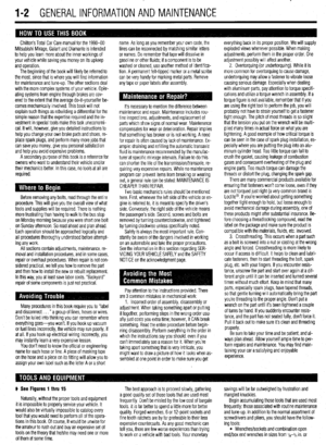 2
2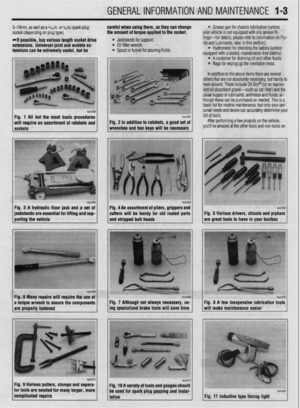 3
3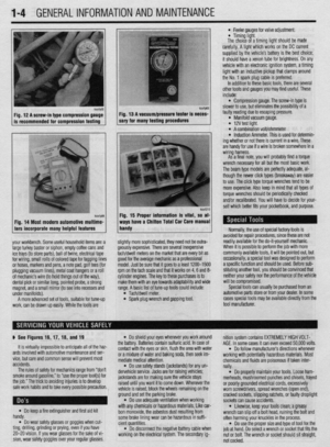 4
4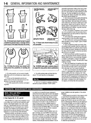 5
5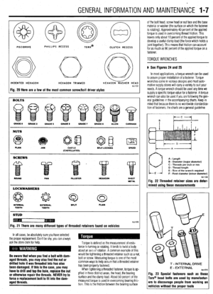 6
6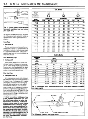 7
7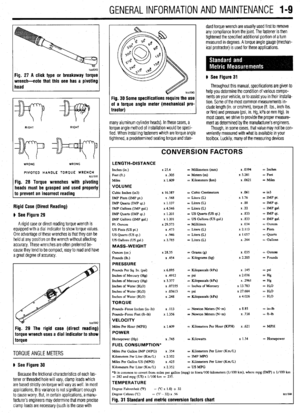 8
8 9
9 10
10 11
11 12
12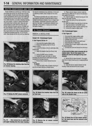 13
13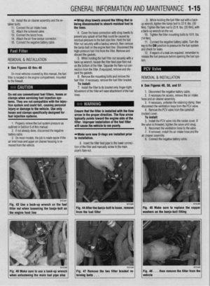 14
14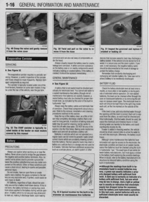 15
15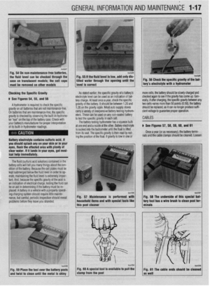 16
16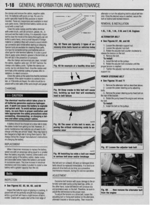 17
17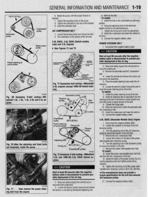 18
18 19
19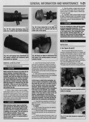 20
20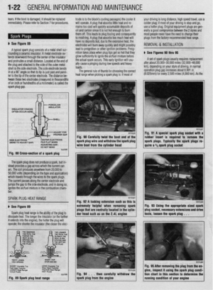 21
21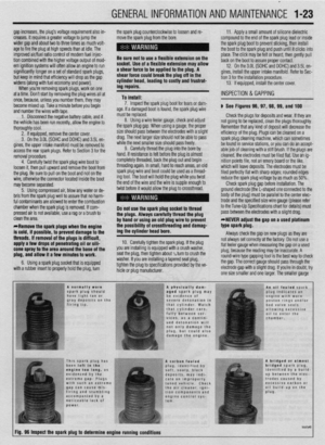 22
22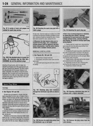 23
23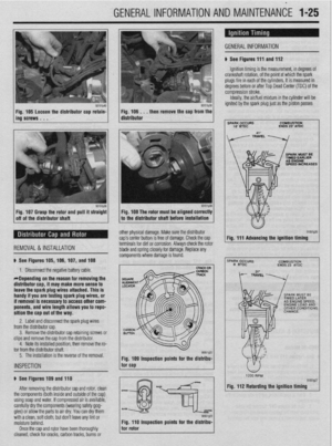 24
24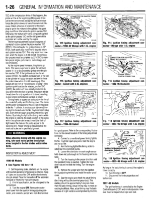 25
25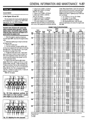 26
26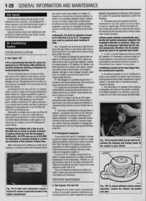 27
27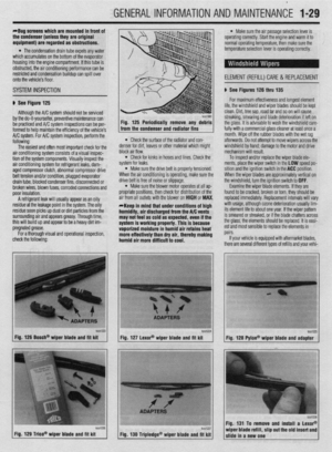 28
28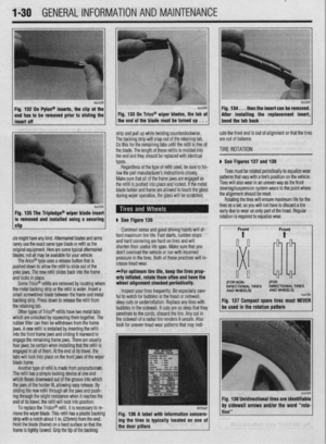 29
29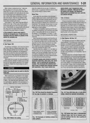 30
30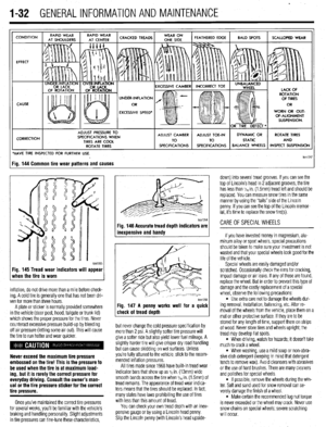 31
31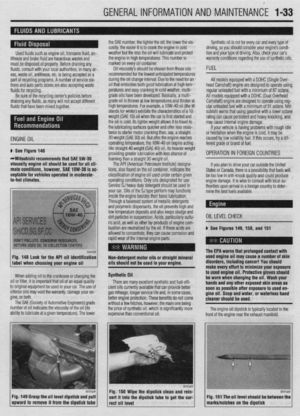 32
32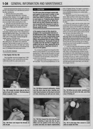 33
33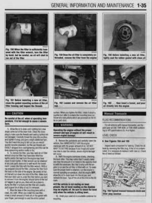 34
34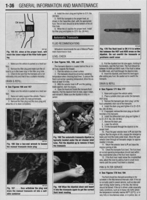 35
35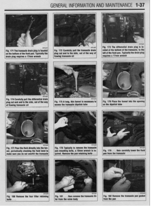 36
36 37
37 38
38 39
39 40
40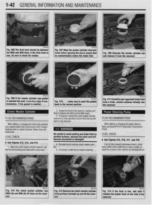 41
41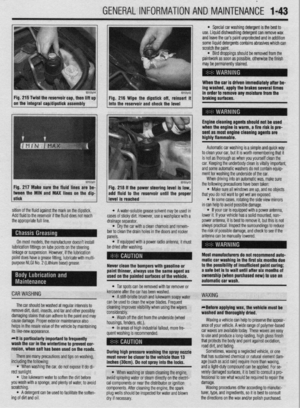 42
42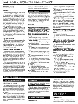 43
43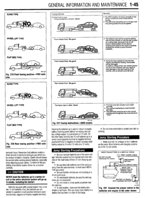 44
44 45
45 46
46 47
47 48
48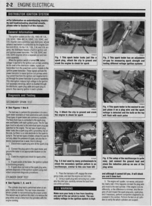 49
49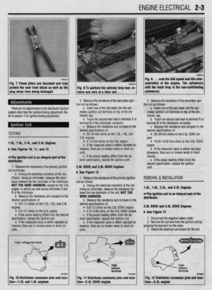 50
50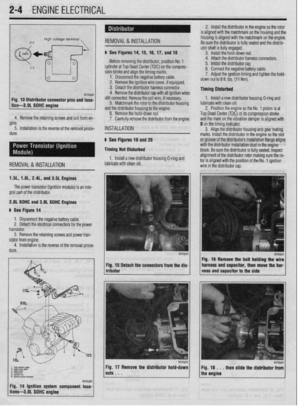 51
51 52
52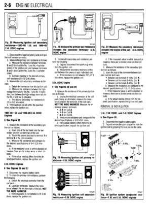 53
53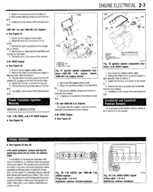 54
54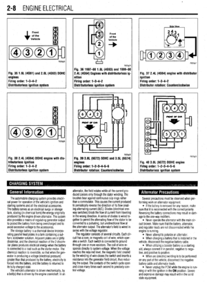 55
55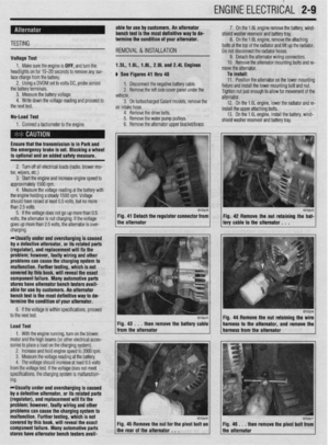 56
56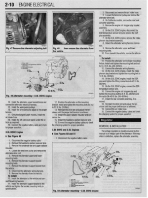 57
57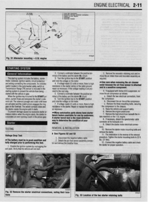 58
58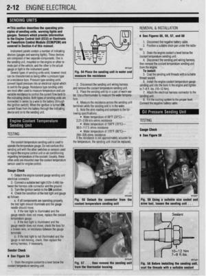 59
59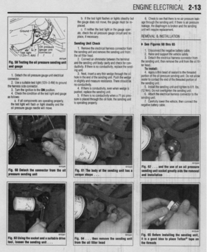 60
60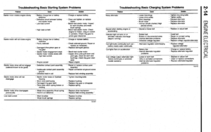 61
61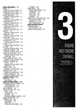 62
62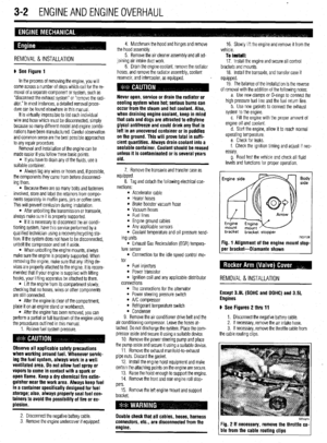 63
63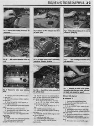 64
64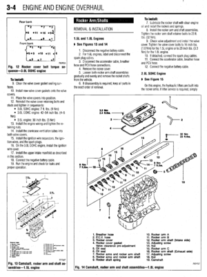 65
65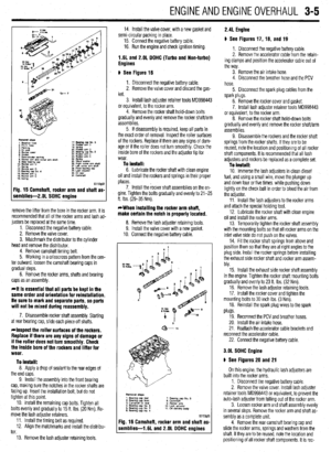 66
66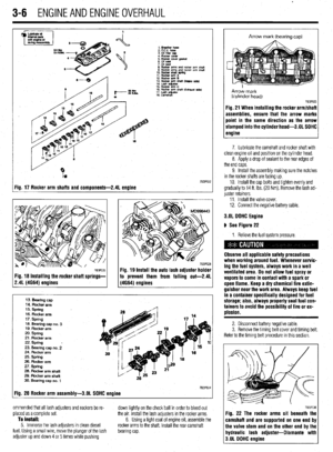 67
67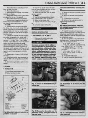 68
68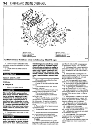 69
69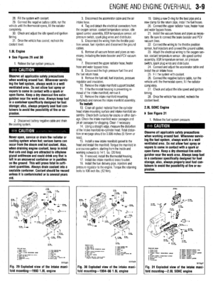 70
70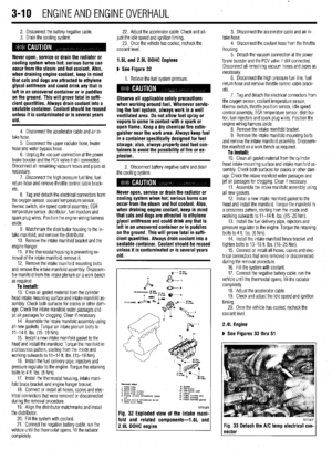 71
71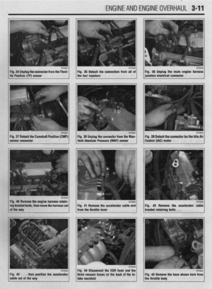 72
72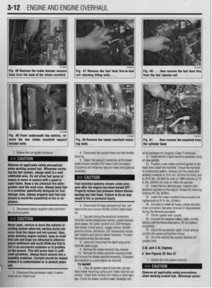 73
73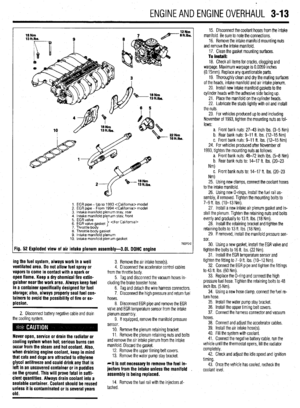 74
74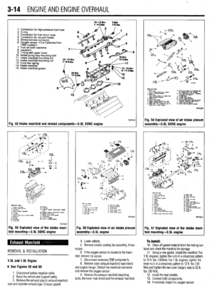 75
75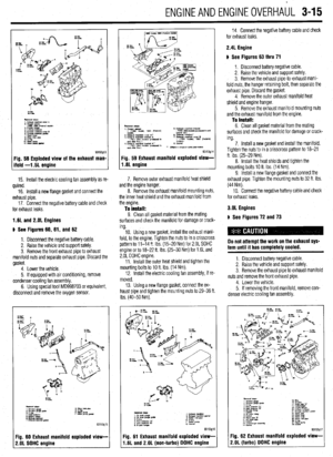 76
76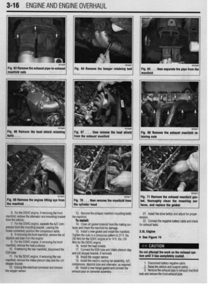 77
77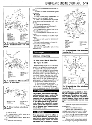 78
78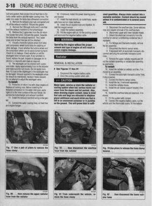 79
79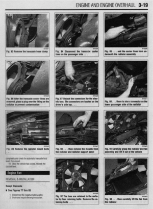 80
80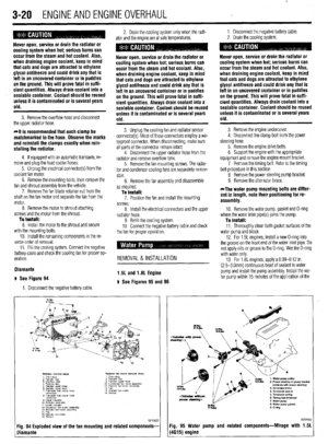 81
81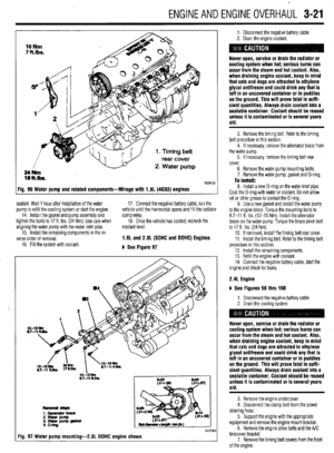 82
82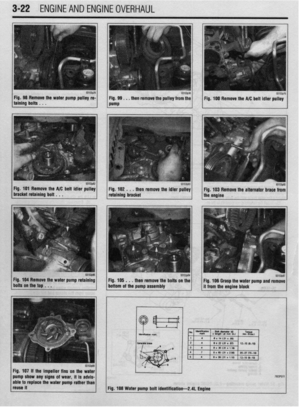 83
83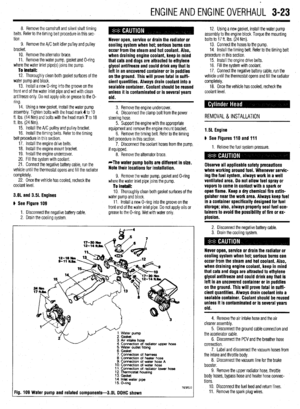 84
84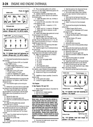 85
85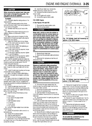 86
86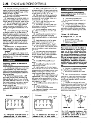 87
87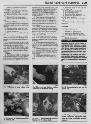 88
88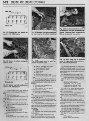 89
89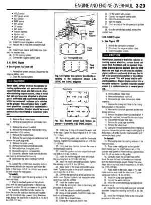 90
90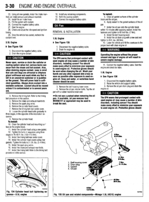 91
91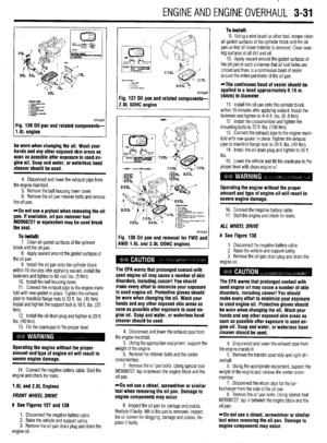 92
92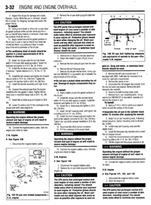 93
93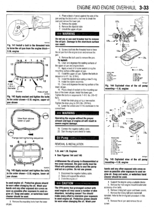 94
94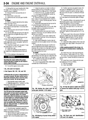 95
95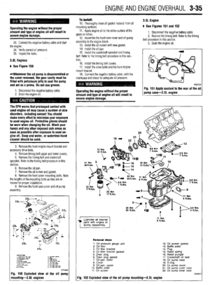 96
96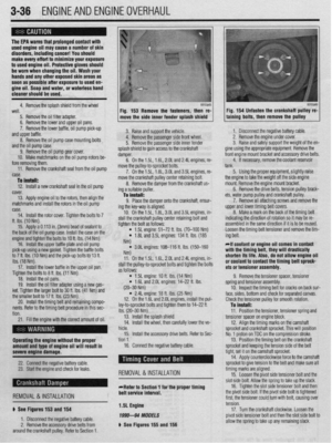 97
97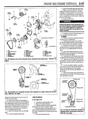 98
98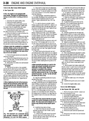 99
99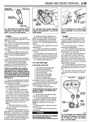 100
100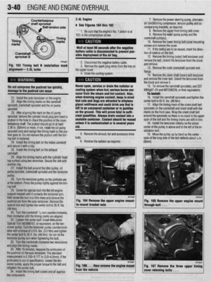 101
101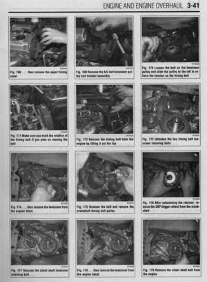 102
102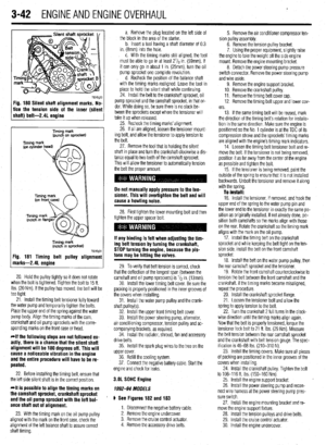 103
103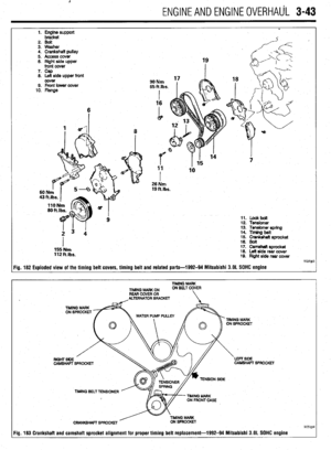 104
104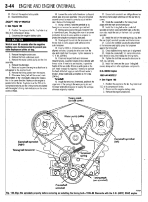 105
105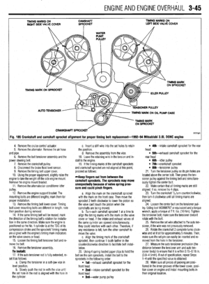 106
106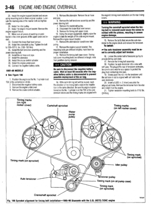 107
107 108
108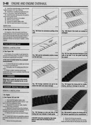 109
109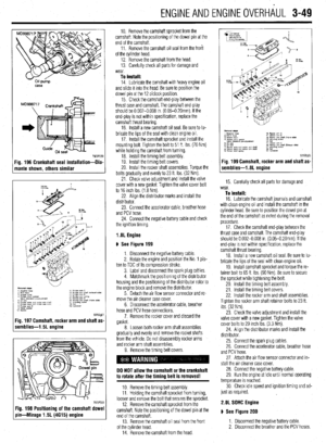 110
110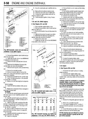 111
111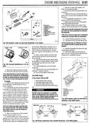 112
112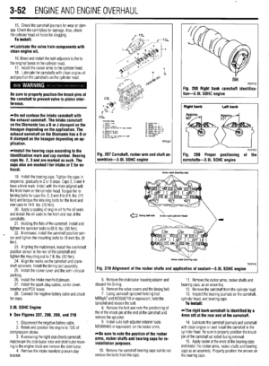 113
113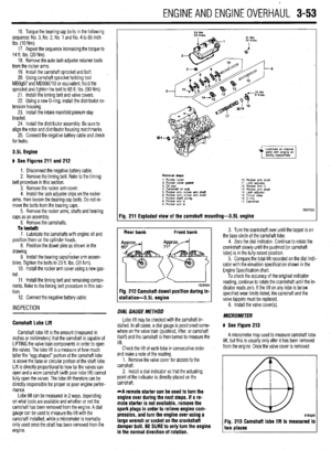 114
114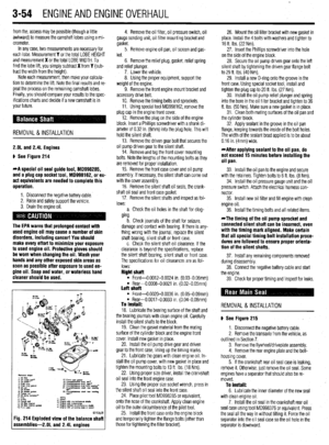 115
115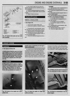 116
116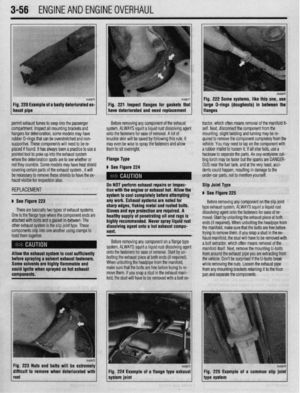 117
117 118
118 119
119 120
120 121
121 122
122 123
123 124
124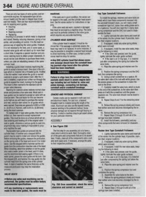 125
125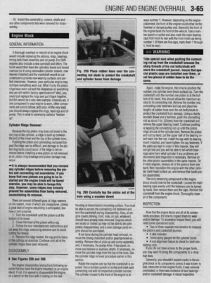 126
126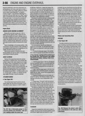 127
127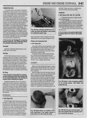 128
128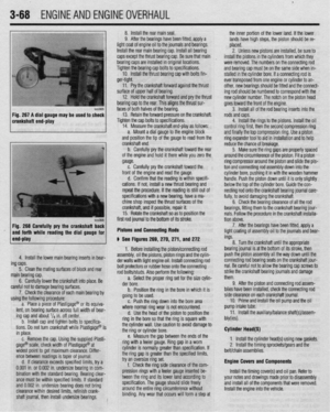 129
129 130
130 131
131 132
132 133
133 134
134 135
135 136
136 137
137 138
138 139
139 140
140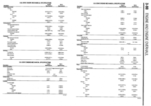 141
141 142
142 143
143 144
144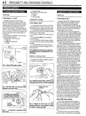 145
145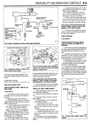 146
146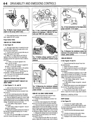 147
147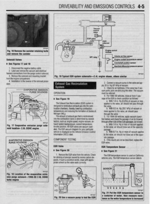 148
148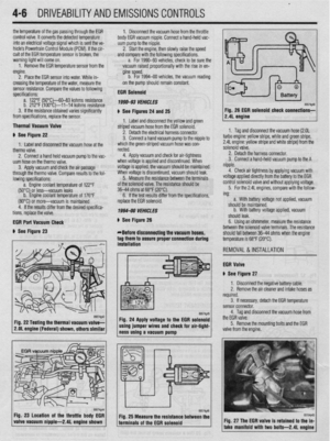 149
149 150
150 151
151 152
152 153
153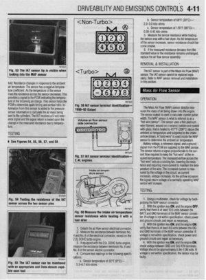 154
154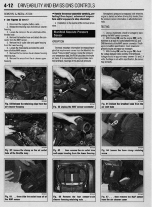 155
155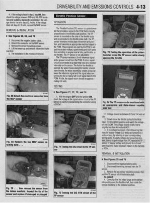 156
156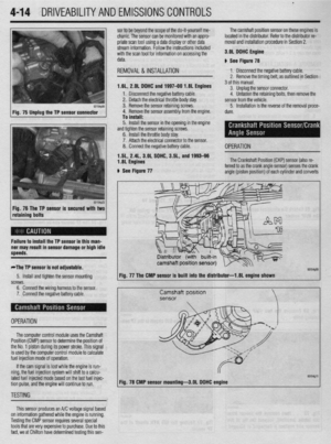 157
157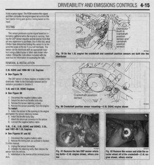 158
158 159
159 160
160 161
161 162
162 163
163 164
164 165
165 166
166 167
167 168
168 169
169 170
170 171
171 172
172 173
173 174
174 175
175 176
176 177
177 178
178 179
179 180
180 181
181 182
182 183
183 184
184 185
185 186
186 187
187 188
188 189
189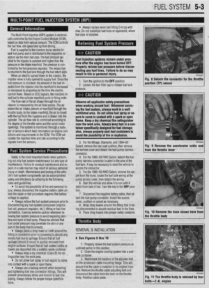 190
190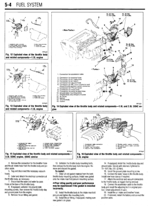 191
191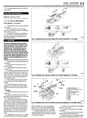 192
192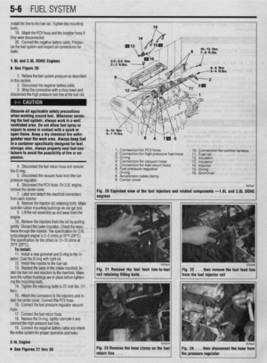 193
193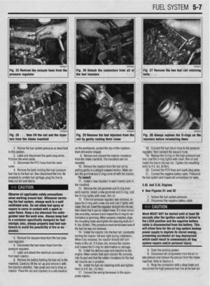 194
194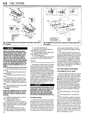 195
195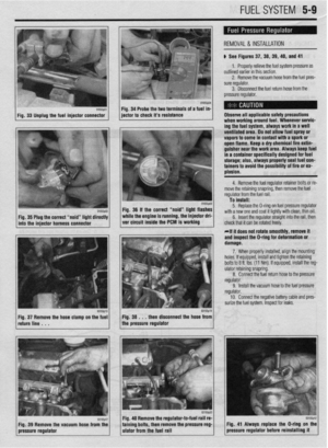 196
196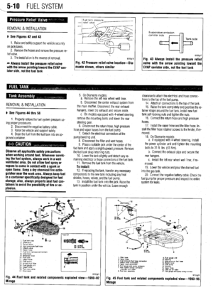 197
197 198
198 199
199 200
200 201
201 202
202 203
203 204
204 205
205 206
206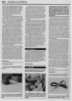 207
207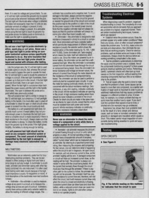 208
208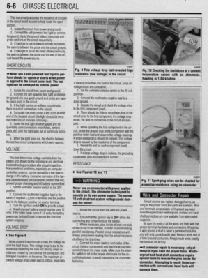 209
209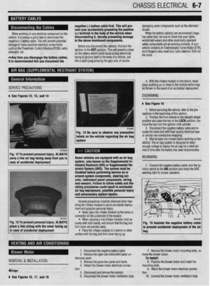 210
210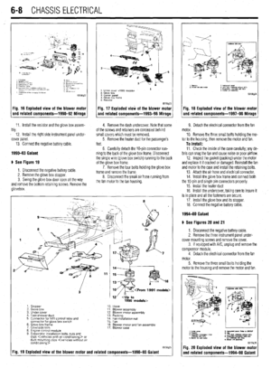 211
211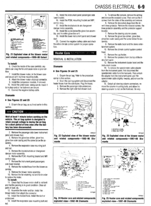 212
212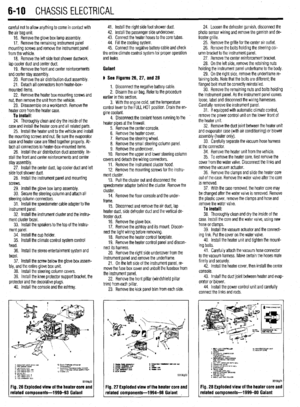 213
213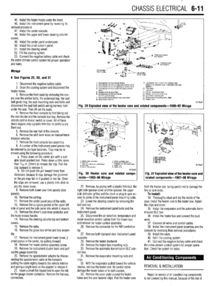 214
214 215
215 216
216 217
217 218
218 219
219 220
220 221
221 222
222 223
223 224
224 225
225 226
226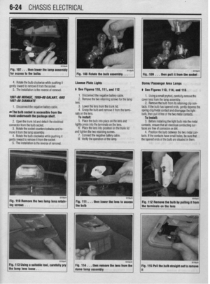 227
227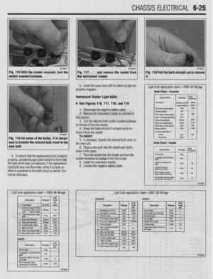 228
228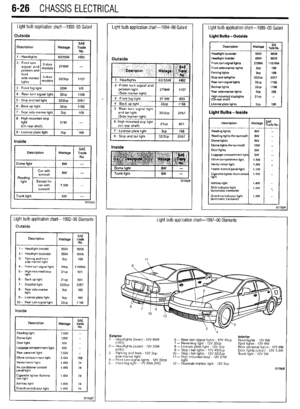 229
229 230
230 231
231 232
232 233
233 234
234 235
235 236
236 237
237 238
238 239
239 240
240 241
241 242
242 243
243 244
244 245
245 246
246 247
247 248
248 249
249 250
250 251
251 252
252 253
253 254
254 255
255 256
256 257
257 258
258 259
259 260
260 261
261 262
262 263
263 264
264 265
265 266
266 267
267 268
268 269
269 270
270 271
271 272
272 273
273 274
274 275
275 276
276 277
277 278
278 279
279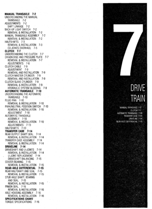 280
280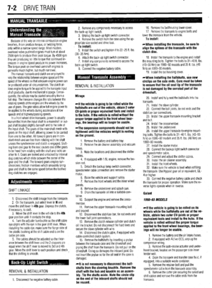 281
281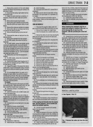 282
282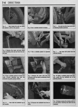 283
283 284
284 285
285 286
286 287
287 288
288 289
289 290
290 291
291 292
292 293
293 294
294 295
295 296
296 297
297 298
298 299
299 300
300 301
301 302
302 303
303 304
304 305
305 306
306 307
307 308
308 309
309 310
310 311
311 312
312 313
313 314
314 315
315 316
316 317
317 318
318 319
319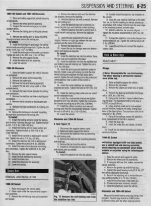 320
320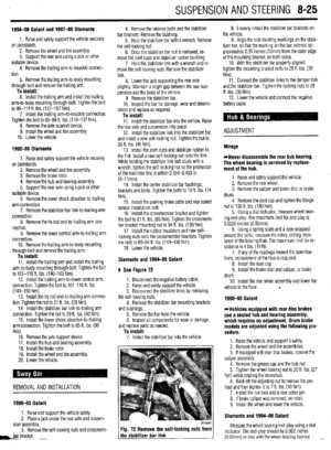 321
321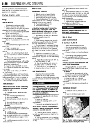 322
322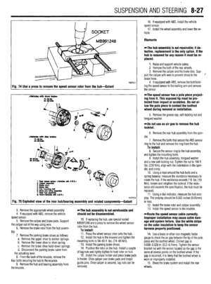 323
323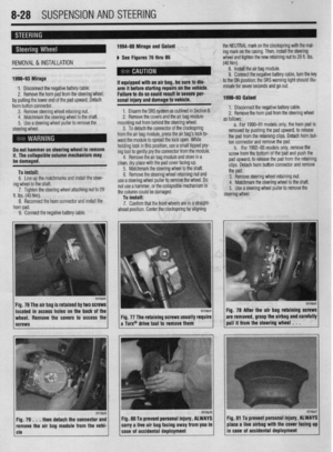 324
324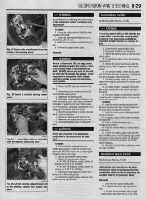 325
325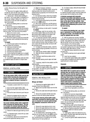 326
326 327
327 328
328 329
329 330
330 331
331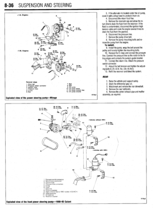 332
332 333
333 334
334 335
335 336
336 337
337 338
338 339
339 340
340 341
341 342
342 343
343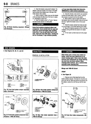 344
344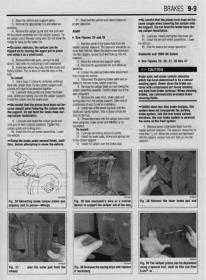 345
345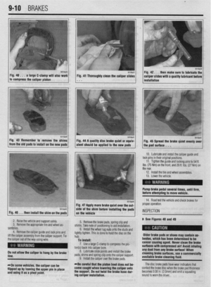 346
346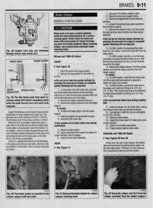 347
347 348
348 349
349 350
350 351
351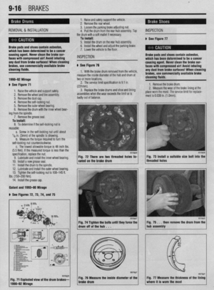 352
352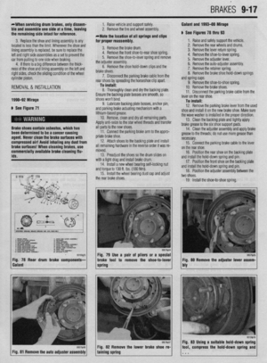 353
353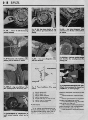 354
354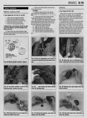 355
355 356
356 357
357 358
358 359
359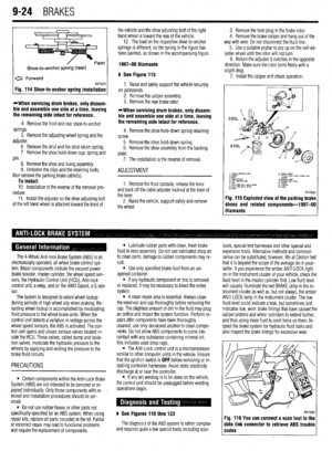 360
360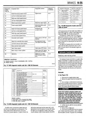 361
361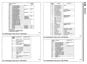 362
362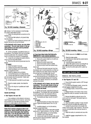 363
363 364
364 365
365 366
366 367
367 368
368 369
369 370
370 371
371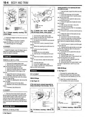 372
372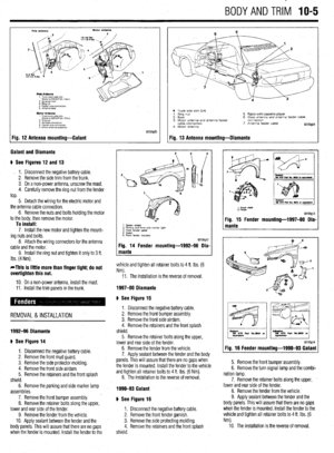 373
373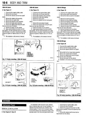 374
374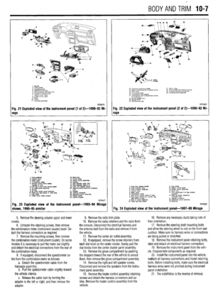 375
375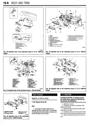 376
376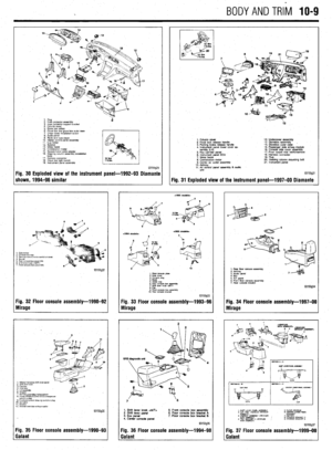 377
377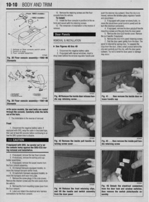 378
378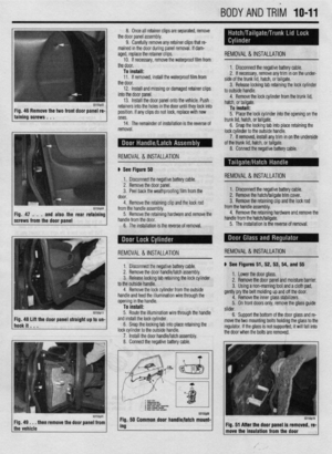 379
379 380
380 381
381 382
382 383
383 384
384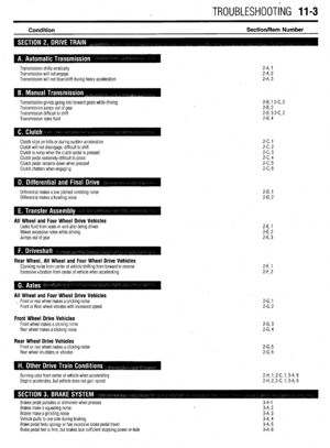 385
385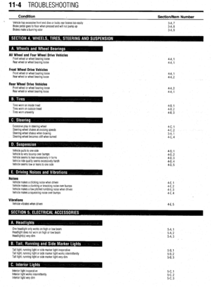 386
386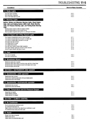 387
387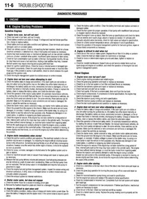 388
388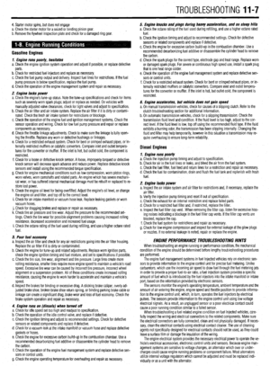 389
389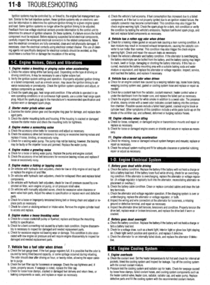 390
390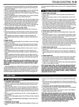 391
391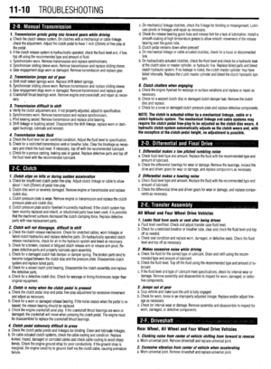 392
392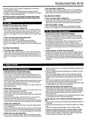 393
393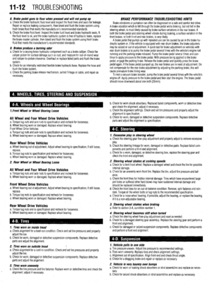 394
394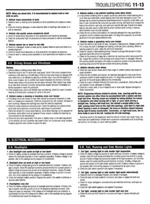 395
395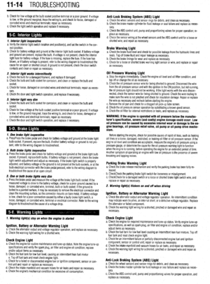 396
396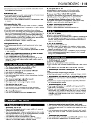 397
397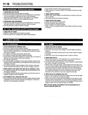 398
398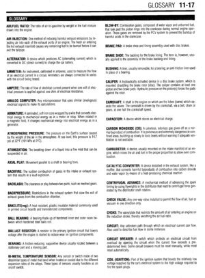 399
399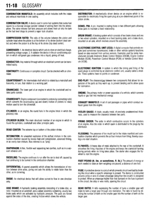 400
400 401
401 402
402 403
403 404
404 405
405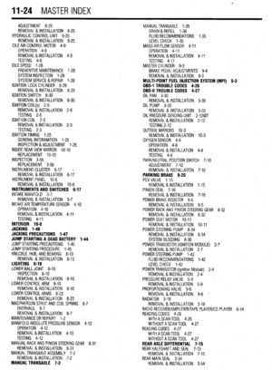 406
406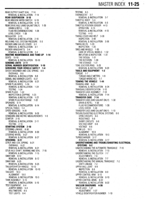 407
407
