Page 209 of 408

.
6-6 CHASSIS ELECTRICAL
This test already assumes the existence of an open
in the circuit and it is used to help locate the open
portion
1. Isolate the circuit from power and ground.
2. Connect the self-powered test light or ohmme-
ter ground clip to the ground side of the circuit and
probe sections of the circuit sequentially.
3. If the light is out or there is infinite resistance,
the open is between the probe and the circuit ground.
4. If the light is on or the meter shows continuity,
the open is between the probe and the end of the cir-
cuit toward the power source.
SHORT CIRCUITS
*Never use a self-powered test tight to per-
form checks for opens or shorts when power Fig. 10 Checking the resistance of a coolant
temperature sensor with an ohmmeter.
Reading is 1.04 kilohms
is applied to the circuit under test. The test
linht man he dmn~nsrl hu nutnitls nnuva~ if there is more than one load in the circuit, since all m.3.m. “Y.. “1 “ulll”y”” u, ““..7IYG p”“lz’.
1. Isolate the circuit from power and ground.
2. Connect the self-powered ’ .,.*. ,
ted ugnt or onmme-
ter ground clip to a good ground
and probe any easy-
to-reach point in the circuit.
3. If the light comes on or there is continuity,
there is a short somewhere in the circuit.
4. To isolate the short, probe a test point at either
end of the isolated circuit (the light should be on or
the meter should indicate continuity).
5. Leave the test light probe engaged and se- voltage drops are cumulative.
1. Set the voltmeter selector switch to the 20 volt
^,.^X^..
pJbl1IUII.
2. Connect the multimeter negative lead to a
good ground.
3. Operate the circuit and check the voltage prior
.
to the hrst component (load).
4. There should be little or no voltage drop in the
circuit prior to the first component. If a voltage drop
exists, the wire or connectors in the circuit are sus-
WY.+
)JGW 5. While operating the first component in the cir-
.
positive meter lead and observe the voltage readings.
A small voltage drop should be noticed. This voltage
drop is caused by the resistance of the component.
6. Repeat the test for each component (load)
de .-IL- .‘.. .I
uuwn me crrcun. quentially open connectors or switches, remove
parts, etc. until the light goes out or continuity is bro-
ken
6. When the light goes out, the short is between
the last two circuit components which were opened,
nl -r*l?I-
VuLlHbt
This test determines voltage available from the
battery and should be the first step in any electrical
troubleshooting procedure after visual inspection,
Many electrical problems, esoeciallv on comouter
controlled systems, can be caused by a low state of 7. If a large voltage drop is noticed, the preceding
component, wire or connector is suspect.
# See Figures
10 and 11
charge in the battery. Excessive corrosion at the bat-
tery cable terminals can cause poor contact that will
prevent proper charging and full battery current flow,
1. Set the voltmeter selector switch to the 20V
position.
2. Connect the multimeter negative lead to the
h*+tnn,‘n nnn,,,;~,,. , ..^,a ^-L.--:^^l --_I ‘I- ---!I?... Never use an ohmmeter with power applied
to the circuit. The ohmmeter is designed to
operate on its 0 wn power supply. The normal
1^
. . . . . Fig. 11 Spark plug wires can be checke;
MW~ 3 IlG~dllYt: t-1 pUSI UI Lellllllldl allU lilt, pUSlIlVe lead to the battery’s positive (t) post or terminal.
3. Turn the ignition switch ON to provide a load,
4. A well charged battery should register over 12
volts. If the meter reads below 11 5 vnlts tha hq*anr
_ _ .-, . power may be insufficient to operate the eler ii! volt electrical system voltage could dam-
age the meter!
1. Isolate the circuit from the vehicle’s power
CnlOrAn I)““IW. 2. Ensure that the ignition key is OFF when dis- Almost anyone can replace damaged wires, as
long as the proper tools and parts are available. Wire
and terminals are available to fit almost any need.
Even the specialized weatherproof, molded and hard
shell connectors are now cl mdicm available from aftermarket
system properly.
connecting any components or the battery. ““yp,8w’“.
3. Where necessary, also isolate at least one side Be sure the ends of all the wires are fitted with the
VOLTAGEDROP of the circuit to be checked, in order to avoid reading proper terminal hardware and connectors. Wrapping
parallel resistances. Parallel circuit resistances will a wire around a stud is never a permanent solution
# See Figure 9 always give a lower reading than the actual resistance and will only cause trouble later. Replace wires one at
When current flows through a load, the voltage be- of eifhy n< +hn hmnnh-r
GI “I II It: “I a lb1 It?>. a time to avoid confusion. Always route wires exactly
4.
Connect the meter leads to both sides of the the same as the factory.
yond the load drops. This voltage drop is due to the
resistance created by the load and also by small re- circuit (wire or component) and read the actual mea-
sured ohms on the meter scale. Make sure the selec- *If connector repair is necessary, only at-
sistances created by corrosion at the connectors and
tor switch is set to the proper ohm scale for the cir- tempt it if you have the proper tools. Weath-
damaged insulation on the wires. The maximum al- erproof and hard shell connectors require
lowable voltage drop under load is critical, especially cuit being tested, to avoid misreading the ohmmeter
test value. spectal tools to release the pins inside the
connector. Attempting to repair these con-
nectors with conventional hand tools will
damage them.
Page 210 of 408
 battery cable. This will prevent potential
damage to ma")
I I
CHASSIS ELECTRICAL 6-7
When working on any electrical component on the
vehicle, it is always a good idea to disconnect the
negative (-) battery cable. This will prevent potential
damage to many sensitive electrical components
such as the Powertrain Control Module (PCM), radio,
alternator, etc.
*Any time you disengage the battery cables,
it is recommended that you disconnect the negative (-) battery cable first. This will pre-
vent your accidentally grounding the positive
(+) terminal to the body of the vehicle when
disconnecting it, thereby preventing damage
to the above mentioned components.
Before you disconnect the cable(s), first turn the
ignition to the OFF position. This will prevent a draw
on the battery which could cause arcing (electricity
trying to ground itself to the body of a vehicle, just
like a spark plug jumping the gap) and, of course, damaging some components such as the alternator
diodes.
When the battery cable(s) are reconnected (nega-
tive cable last), be sure to check that your lights,
windshield wipers and other electrically operated
safety components are all working correctly. If your
vehicle contains an Electronically Tuned Radio (ETR),
don’t forget to also reset your radio stations. Ditto for
the clock.
SERVICE PRECAUTIONS
b See Figures 12,13, and 14
Fig, 14 Be sure to observe any precaution
labels on the vehicle regarding the air bag
system
Fig. 12 To prevent personal injury, ALWAYS
*
carry a-live -ah bag fac!ng away from you in 1
1 case of accidental deployment Some vehicles are equipped wtth an air bag
-.-‘--
syr1em, aiscl Known as I11 -I-- ‘------- -- sLe Supplemental in- fiatable Restraint (SIR) o r Suouiementai Fiea
l With the inflator module on the bench, never
place anything on or close to the module which may
be thrown in the event of an accidental deployment.
DISARMING
# See Figure 15
1. Before servicing the vehicle, refer to the pre-
cautions in the beginning of this section.
2. Position the front wheels in the straight-ahead
position and place the key in the LOCK position. Re-
move the key from the ignition lock cylinder.
3. Disconnect the negative battery cable and in-
sulate the cable end with high-quality electrical tape
or similar non-conductive wrapping.
4. Wait at least one minute before working on the
vehicle. The air baa svstem is desianed to retain
enough voltage to deploy the air bag for a short pe-
riod of time after the battery has been disconnected.
1. Connect the neoative batters cable. turn the ia-
3, hold se-
e bag and
trim cover are pointed away.
l Place the inflator module on a bench or other
surface with the bag and trim cover facing up.
7!r!3PG93 Fig. 15 insulate the negative battery cable
.I
to prevent accidental deployment of the air
bag place a live airbag with the cover facing up
in case of accidental deployment
REMOVAL &INSTALLATION
Mirage
b See Figures 16, 17, and 18 1. Disconnect the negative battery cable.
2. Remove the right side instrument panel un-
dercover panel.
3. Remove the glove box panel and frame.
4. Detach the blower motor electrical connec-
tion.
5. Disconnect and remove the resistor.
6. Disconnect the blower motor ventilation tube. 7. Remove the blower motor mounting bolts, re-
move the blower motor.
To install:
8. Position the blower motor and install the
mounting bolts.
9. Attach the blower motor electrical connec-
tion.
10. Connect the blower motor ventilation tube.
Page 211 of 408

6-8 CHASSIS ELECTRICAL
Fig. 16 Exploded view of the blower motor
and related components-1990-92 Mirage
11. Install the resistor and the glove box assem- W 12. Install the right side instrument panel under-
cover panel.
13. Connect the negative battery cable.
1990-93 Galant
# See Figure 19
1. Disconnect the negative battery cable.
2. Remove the glove box stopper.
3. Swing the glove box door open all the way
and remove the bottom retainina screws. Remove the
glovebox
1 Under cover 4993 models, 1
2 Glove box
3 corner pane,
4 Glove box frame
5 RBSlStOr
93156~23
Fig. 17 Exploded view of the blower motor
and related components-1993-96 Mirage
4. Remove the dash undercover. Note that some 9. Detach the electrical connector from the fan
ot the screws and retainers are concealed behind
small covers which must be removed.
5 Remove the heater duct for the passenger’s
feet.
6. Carefully detach the lo-pin connector run-
ning to the back of the glove box frame. Disconnect
the single wire (glove box switch) running to the back
of the glove box frame.
7. Remove the four bolts holding the glove box
frame and remove the frame.
8. Disconnect the small air hose running from
the fan motor to the fan housing. motor.
10. Remove the three small bolts holding the mo-
tor to the housing, then remove the motor and fan.
To install: 11. Check the inside of the case carefully: any de-
bris can snag the fan and cause noise or poor airflow.
12. Inspect the gasket (packing) under the motor
and replace it if cracked or damaged. Reinstall the fan
and motor to the case and Install the retaining bolts.
13. Attach the air hose and electrical connector.
14. Install the glove box frame and connect both
the lo-pin and sinqle pin connectors properly.
15. Install the heater duct
16. Install the undercover, taking care to insure it
is in place and all the fasteners are secure.
17. Install the glove box and its stopper.
18. Connect the negative battery cable.
:ig. 19 Exploded view of the blower motor and related components-1990-93 Galant
1. stopper
‘2 Glove box
3 Under cover
4 Foot shower duct
5 Connector for MFI control relay and ,
connector for glove box swtch
6 Glove box frame
7 Cowl side trim
8 Engine control module
9 Evaporator lnstallatlon bolts, nuts and
clips or
duct mounting clips Kvehlcles wthout air
condltionlng>
Fig. 18 Exploded view of the blower motor
and related components-1997-00 Mirage
--.
8
12’ Hose
Blower assemblv
Blower motor assembly
Packtng
;;c, tnstallatlon nut
Blower motor and fan assembly
Blower case
1994-00 Galant
) See Figures 20 and 21
1. Disconnect the negative battery cable.
2. Remove the three instrument panel under-
cover mounting screws and remove the cover.
3 If equipped with A/C, unplug and remove the
compressor module.
4. Detach the electrical connector from the fan
motor.
5. Remove the three small bolts holding the
motor to the housing and remove the motor and fan.
; y&M 5 m- M ,RC m .3RcuP
3 lulomafs corn-r ECU :2%brtr-Mbi&C>
.“eM *nn mi
1 slmhn.m”m,n 8 ~y~tipJ*-m-=%9 md
S sa*n”nlUSW
931561
Fig. 20 Exploded view of the blower mote
and related comoonents-1994-98 Galan
Page 212 of 408

CHASSIS ELECtRldAL 6-9
93156g27 Fig. 21 Exploded view of the blower motor
and related components-1999-00 Galant
To install:
6. Check the inside of the case carefully; any
debris can snag the fan and cause noise or poor air-
flow.
7. Install the blower motor, in the blower case
and secure with the three mounting bolts,
8. Attach the blower motor electrlcal connector,
9. Install the compressor module, if removed.
10. Install the undercover, takmg care to insure it
is in place and all the fasteners are secure.
11. Connect the negative battery cable.
Diamante
u See Figures 22 and 23
1. Disarm the air bag, as outlined earlier in this
section.
Wait at least 1 minute before working on the
vehicle. The air bag system is designed to
retain enough voltage to deploy the air bag
for a short period of time even after the bat-
tery has been disconnected.
2. Remove the passenger side lower instrument
panel and shower duct,
3. Remove the glove box striker, glove box,
glove box outer casing and the screw below the as-
sembly.
4. Remove the evaporator case mounting bolt
and nut.
5. Remove the inside/outside air changeover
damper motor assembly.
6 Remove the PCM, mounting bracket and MFI
control relay.
7. Remove the instrument panel passengers
side lower bracket.
8. Remove the molded hose from the blower as-
sembly.
9. Remove the blower motor assembly.
10. Remove the fan retaining nut and fan in order
to replace the motor,
To install: 11. Check that the blower motor shaft is not bent
and that the packing is in good condition, Clean all
parts of dust, etc.
12. Assemble the motor and fan. Install the
blower motor then attach the connector.
13. Install the molded hose. Install the duct or
undercover.
14. Install the evaporator case mounting bolt and
nut. 15. Install the instrument panel passengers side
lower bracket.
16. Install the PCM, mounting bracket and MFI
control relay.
17. Install the inside/outside air changeover
damper motor assembly.
18. Install the screw below the glove box assem-
bly, and the entire glove box unit.
19. Install the lower instrument panel and shower
duct.
20. Connect the negative battery cable and check
the entire climate control system for proper opera-
tion.
REMOVAL & INSTALLATION
Diamante
u See Figures 24
and 25
1. Disarm the air bag Refer to the procedure
earlier in this section.
2. Dram the cooling system and disconnect the
heater hoses from the core tubes. Plug the hoses.
3. Remove the passenger side undercover.
4. Remove the right side foot shower duct. 5. To remove the console, remove the ashtray
and remove the revealed screw. Then remove the 4
screws from the sides of the assembly and remove.
6. Remove the decorative plugs from the drl-
ver’s knee protector. Remove the revealed screws, the
knee protector assembly and the protector support
bracket.
7. Remove the steering column covers.
8. Remove the glove box striker, glove box,
glove box outer casing and the screw below the as-
sembly.
9. Remove the radio bezel and the stereo enter-
tainment system.
10. Remove the climate control system control
head.
11. Remove the cup holder.
12. Remove the speakers from the top of the in-
strument panel.
13. Remove the instrument cluster bezel and the
instrument cluster.
14. To remove the speedometer cable adapter
from the instrument panel, first disconnect the
speedometer cable from the transaxle. Then unlock
the adapter from the instrument panel, pull the
speedometer cable slightly inwards, and remove the
adapter
15. Detach all steering column connectors, re-
move the column mounting bolts, and allow the
steering column to rest on the front seat. Be very
Fig. 23 Exploded view of the blower motor
and related components-1997-00 Dia-
Fig. 25 Heater core and related components
exploded view-1997-00 Diamante
Page 213 of 408

640 CHASSIS ELECTRICAL
careful not to allow anything to come in contact with
the air bag unit.
16. Remove the glove box lamp assembly.
17. Remove the remaining instrument panel
mounting screws and remove the instrument panel
from the vehicle.
18. Remove the left side foot shower ductwork,
lap cooler duct and center duct.
19. Remove the front and center reinforcements
and center stay assembly.
20. Remove the air distribution duct assembly.
21. Detach all connectors from heater-box-
mounted items.
22. Remove the heater box mounting screws and
nut, then remove the unit from the vehicle.
23. Disassemble on a workbench. Remove the
heater core from the heater case.
To install:
24. Thoroughly clean and dry the inside of the
case and install the heater core and all related parts.
25. Install the heater unit to the vehicle and install
the mounting screws and nut. Be sure the evaporator
case and heater case are fitted together properly. At-
tach all connectors to heater-box-mounted items.
26. Install the air distribution duct assembly. In-
stall the front and center reinforcements and center
stay assembly.
27. Install the center duct, lap cooler duct and left
side foot shower duct.
28. Install the instrument panel and mounting
screws.
29. Install the glove box lamp assembly.
30. Secure the steering column and attach all
steering column connectors.
31. Install the speedometer cable adapter to the
instrument panel.
32. Install the instrument cluster and the instru-
ment cluster bezel.
33. Install the speakers to the top of the instru-
ment panel.
34. Install the cup holder.
35. Install the climate control system control
head.
36. Install the stereo entertainment system and
bezel.
37. Install the screw below the glove box assem-
bly, and the entire glove box unit.
38. Install the steering column covers.
39. Install the knee protector support bracket, the
protector and the decorative plugs.
40. Install the console and the ashtray. 41. Install the right side foot shower duct.
42. Install the passenger side undercover.
43. Connect the heater hoses to the core tubes.
44. Fill the cooling system.
45. Connect the negative battery cable and check
the entire climate control system for proper operation
and leaks.
Galant
# See Figures 26, 27, and 28
1. Disconnect the negative battery cable.
2. Disarm the air bag. Refer to the procedure
earlier in this section.
3. With the engine cold, set the temperature
control lever to the FULL HOT position. Drain the en-
gine coolant.
4. Disconnect the coolant hoses running to the
heater pipes at the firewall.
5. Remove the center console.
6. Remove the heater cover.
7. Remove the steering wheel.
8. Remove the small steering column panel.
9. Remove the undercover.
10. Remove the upper and lower steering column
covers and detach the wiring connectors.
11. Remove the instrument cluster hood.
12. Remove the mounting screws for the instru-
ment cluster.
13. Pull the cluster out and disconnect the
speedometer adapter behind the cluster. Remove the
cluster.
14. Remove the floor console and the under-
frame.
15. Disconnect and remove the air duct, lap
heater duct, side defroster duct and the vertical de-
froster duct.
16. Remove the glove box.
17. Remove the ashtray and its mount. Discon-
nect the light wiring before removing.
18. Remove the heater control faceplate.
19. Remove the heater control panel and discon-
nect its harness.
20. Remove the right side undercover from the
instrument panel and remove the underframe.
21. On the left side of the instrument panel, re-
move the fuse box cover and unbolt the fusebox from
the instrument panel.
22. Remove the front pillar (windshield pillar
trim) from each pillar.
23. Remove the kick panel trim from each side.
Fig. 26 Exploded view of the heater core and
related components-1990-93 Galant
:IQ. 27 Exploded view of the heater core and
-elated components-1994-98 Galant 24. Loosen the defroster garnish, disconnect the
photo sensor wiring and remove the garnish and de-
froster grille.
25. Remove the grille for the center air outlet.
26. Remove the bolts holding the steering col-
umn bracket to the instrument panel.
27, Remove the center reinforcement bracket.
28. On the left side, remove the retaining nuts
holding the instrument panel underframe to the body.
29. On the right side, remove the underframe re-
taining bolts. Note that the bolts are different; the
flanged bolt must be correctly reinstalled.
30. Remove the remaining nuts and bolts holding
the instrument panel. As the instrument panel comes
loose, label and disconnect the wiring harnesses.
Carefully remove the instrument panel.
31. If equipped with automatic climate control,
remove the power control unit on the lower front of
the heater unit.
32. Remove the duct joint between the heater unit
and evaporator case (with air conditioning) or blower
assembly (heater only).
33. Carefully separate the vacuum hose harness
at the connector.
34. Remove the heater unit from the vehicle.
35. To remove the heater core, first remove the
cover from the water valve. Disconnect the links and
remove the vacuum actuator.
36. Remove the clamps and slide the heater core
out of the case. Remove the water valve after the core
is removed.
37. With the case removed, the heater core may
be changed after the water valve is removed. Remove
the plastic cover, remove the clamps and hose and
remove the water valve.
To install:
38. Thoroughly clean and dry the inside of the
case. Install the core and the water valve, using new
hose or clamps.
39. Install the vacuum actuator and the connect-
ing link. Put the cover on the water valve.
40. Install the heater unit and tighten the mount-
ing bolts.
41. Carefully attach the vacuum hose connector
to the vacuum harness. Make certain the hoses mate
firmly and securely.
42. Install the heater cover, then install the center
console.
43. Install the duct joint between heater and evap-
orator or blower.
44. Install the power control unit and carefully
connect the links and rods.
Fig. 28 Exploded view of the heater core and
related components-1999-00 Galant
Page 214 of 408

CHASSIS ELECTRICAL 6-11
45. Install the heater hoses under the hood.
46. Install the mstrument panel by reversing its
removal procedure.
47. Install the center console.
48. install the upper and lower steering column
covers.
49. Install the center panel undercover.
50. Install the small column panel.
51. Install the steering wheel.
52. Fill the cooling system.
53. Connect the negative battery cable and check
the entire climate control system for proper operation
and leaks.
Mirage
# See Figures 29, 30, and 31
1. Disconnect the negative battery cable.
2. Drain the cooling system and disconnect the
heater hoses.
3. Remove the front seats by removing the cov-
ers over the anchor bolts, the underseat tray, the seat
belt guide ring, the seat mounting nuts and bolts and
disconnect the seat belt switch wiring harness from
under the seat. Then lift out the seats
4. Remove the floor console by first taking out
the coin holder and the console box tray. Remove the
remote control mirror switch or cover. All of these
items require only a plastic trim tool to carefully pry
them out.
5. Remove the rear half of the console.
6. Remove the shift lever knob on manual trans-
mission vehicles.
7. Remove the front console box assembly.
8. A number of the instrument panel pieces may
be retamed by pin type fasteners. They may be re-
moved using the following procedure:
a. Press down on the center pin with a suit-
able blunt pointed tool. Press down a little more
than l/re in. (2mm) to release the clip. Pull the
clip outward to remove it.
b. Do not oush the oin inward more than
necessary because it may damage the grommet
or the pin may fall in if pushed in too far. Once
the clips are removed, use a plastic trim stick to
pry the piece loose.
9. Remove both lower cowl trim panels (kick
panels).
10. Remove the ashtray.
11. Remove the center panel around the radio.
12. Remove the sunglass pocket at the upper left
side of panel and the side panel into which it mounts,
13. Remove the drivers side knee protector and
the hood release handle.
14. Remove the steering column top and bottom
covers.
15. Remove the radio.
16. Remove the glove box striker and box assem-
bly.
17. Remove the instrument panel lower cover, 2
small pieces in the center, by pulling forward.
18. Remove the heater control assembly screw.
19. Remove the instrument cluster bezel and pull
out the Qauge assembly.
20. Remove the speedometer adapter by discon-
necting the speedometer cable at the transaxle
pulling the cable Sightly towards the vehicle interior
and giving a Slight twist on the adapter to release it.
21. Insert a small flat-tipped tool to open the tab
on the QauQe cluster connector. Remove the harness
connectors.
Fig. 29 Exploded view of the heater core and related components-1990-92 Mirage
93l%Q% Fig. 30 Heater core and related compo-
nents-1993-96 Mirage
22. Remove, by prying with a plastic trim tool, the
right side speaker cover and the speaker, the upper
side defroster grilles and the clock or plug to gain ac-
cess to some of the instrument panel mounting bolts.
23. Lower the steering column by removing the
bolt and nut.
24. Remove the instrument panel bolts and the
instrument panel.
25 Drsconnect the air selection, temperature and
mode selection control cables from the heater box
and remove the heater control assembly.
26. Remove the connector for the MFI control re-
lay.
27. Remove both stamped steel instrument panel
supports.
28. Remove the heater ductwork.
29. Remove the heater box mounting nuts.
30 Remove the automatic transmission ELC con-
trol box.
31. Remove the evaporator mounting nuts and
clips.
32. With the evaporator pulled toward the vehicle
interior, remove the heater unit. Be careful not to
damage the heater tubes or to spill coolant.
33. Remove the cover plate around the heater
tubes and the core fastener clips. Pull the heater core 34. Thoroughly clean and dry the inside of the
case. Install the heater core to the heater box. Install
the clips and cover,
35. Install the evaporator and the automatic trans-
mission ELC box.
36. Install the heater box and connect the duct
Fig. 31 Exploded view of the heater core and
related components-1997-00 Mirage
from the heater box, being careful not to damage the
fins or tank ends.
To install: I
work.
37. Connect all wires and control cables,
38. Install the instrument panel assembly and the
console by reversmg their removal procedures.
39 Install the seats.
40. Refill the cooling system.
41. Connect the negative battery cable and check
the entire climate control system for proper opera-
tion Check the system for leaks.
REMOVAL &INSTALLATION
Repair or service of air Conditioning components
is not covered by this manual, because of the risk of
Page 215 of 408

6-12 CHASSIS ELECTRICAL
personal injury or death, and because of the legal
ramifications of servicing these components without
the proper EPA certification and experience. Cost,
personal injury or death, environmental damage, and
legal considerations (such as the fact that it is a fed-
eral crime to vent refrigerant into the atmosphere),
dictate that the A/C comoonents on your vehicle 4. Move the air selection controi lever to the RE-
CIRC position. Move the air selection damper FULLY
INWARD and connect the cable to the lever. Adjust as
required. C. Push the outer cable in the direction of the
arrow so that there is no looseness, then secure
should be serviced only’by a Motor Vehicle Air Con-
ditioning (MVAC) trained, and EPA certified automo-
REMOVAL&INSTALLATION tive technician. with the clip.
d. Set the knob for the air outlet changeover
on the control to the DEF position.
e. Set the air outlet changeover damper lever
of the heater unit to the DEF position, then attach
the cable to the lever pin.
f. Push the outer cable in the direction of the
arrow so there is no loosen&s, then secure it
with the clip. *If your vehicle’s A/C system uses R-12 re-
frlgerant and is in need of recharging, the
AK system can be converted over to R-Ma
refrigerant (less environmentally harmful
and expensive). Refer to Section 1 for addi-
tional information on R-12 to R-134a eonver-
sions, and for additional considerations
dealing with your vehicle’s A/C system. ti See Figures 32 thru 45
1. Disconnect the negative battery cable.
2, Unfasten the retaining clips and remove the
center trim panel.
3. Remove the radioltape and/or CD player as-
sembly,
4. Remove the control assembly as follows:
a. Remove the retaining screw(s).
b. Press the lever pin to disconnect the air
outlet changeover damper cable.
*The boss and clamp are needed for the as-
ADJUSTMENT
1. Disconnect the negative battery cable. Remove sembly line d
ever they are
dedures.
n Cnan i luring factory installation, how-
not necessary for service pro-
the glove box, if necessary,
2. Move the mode selection lever to the DE-
FROST position. Move the mode selection damper
lever FULLY INWARD and connect the cable to the
lever. Adiust as required.
3. M&e tht
3 temperature control lever to its
HOlli
5ST position. Move the blend air damper lever
FULL’t
’ DOWNWARD and connect the cable to the
lever. i
4djust as required. b,. dIIal, the boss and clamp with a pair of
nippers, to remove the heater control assembly
from the vehicle.
To install:
5. Install the control panel, as follows:
a. Set the temperature control knob on the
panel to MAX HOT..
b. Set the air mix damper lever at the upper
part of the heater unit to the MAX HOT position,
then attach the cable to the lever pin.
then remove the shi
Fig. 32 Using a suitable prytool, release the
automatic transaxles
93156p27 Fig. 35 . . .
then remove the center trim
panel from the vehicle
/(twiperside)... y Fig 36 Remove the radio retaining screws g. Set the lever for the inside/outside air
changeover on the heater control assemblv to the
air recirculation position.
h. Set the inside/outside air changeover
damper lever of the blower unit to the air recircu-
lation position (with the inside/outside air
changeover damper lever touched to the stopper
of the blower case), then attach the cable to the
lever pin.
i. Push the outer cable in the direction of the
arrow so that there is no looseness, then secure
it with the clip.
j. Properly position the control assembly and
secure with the retaining screw(s).
6. Install the stopper.
7. Connect the negative battery cable and check
the climate control system for proper operation be-
fore installing the remaining components.
8. Install the radio/tape and/or CD player as-
sembly.
9. Install the center trim oanel, makina sure the
clips are engaged properly. -
10. Connect the negative battery cable.
Fig. 34 Remove the two center trim panel
retaining screws . . .
Fig. 37, . . then slide the radio chassis and
bracket out of the instrument Dane1
Page 216 of 408

CHASSIS ELECTRICiL 6-13
.
Fig. 38 Pull the radia far enough out to ac-
cess the electrical connectors . . . 9315fip14 Fig. 39. . . then detach the connectors from
I I Fig. 40 Finally, detach the antenna cable
the rear of the radio and remove the radio from the vehicle
Fig. 41 Remove the heater control panel re-
Fig. 42 Remove the control cable from the
g3156p1g / Fig 43 Remove the control cable from the
bleid door
Cruise control is a speed control system that
maintains a desired vehicle speed under normal dri-
ving conditions. However, steep grades up or down
may cause variations in the selected speeds. The !
electronic cruise control system has the capability to
cruise, coast, resume speed, accelerate, “tap-up” and
“tap-down”.
The main parts of the cruise control system are the
functional control switches, speed control assembly, actuator, intermediate link, auto-cruise control mod-
ule assembly, speed sensor, and the release
switches.
Depending upon the year and/or model of your
vehicle, the cruise control system is either vacuum or
electronically controlled. The cruise control module
assembly contains a low speed limit which will pre-
vent system engagement below 25 mph (40 km/h).
The module is controlled by the functional switches located on a lever on the steering column or steering
wheel and on the instrument panel.
The release switches are mounted on the
brake/clutch/accelerator pedal bracket. When the
brake or clutch pedal is depressed, the cruise control
system is electrically disengaged and the throttle is
returned to the idle position.
 1
1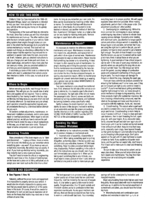 2
2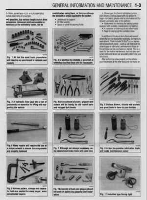 3
3 4
4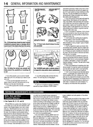 5
5 6
6 7
7 8
8 9
9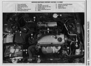 10
10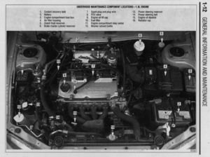 11
11 12
12 13
13 14
14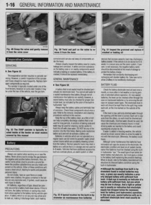 15
15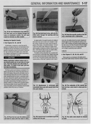 16
16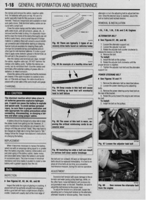 17
17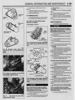 18
18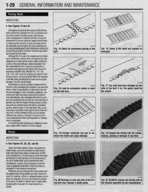 19
19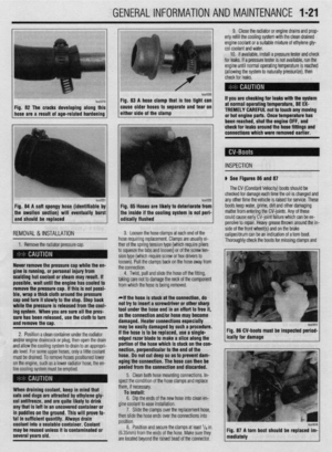 20
20 21
21 22
22 23
23 24
24 25
25 26
26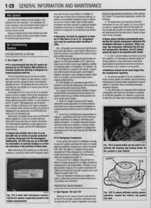 27
27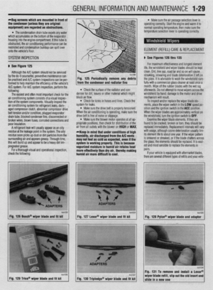 28
28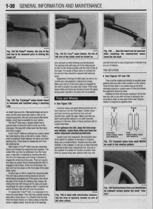 29
29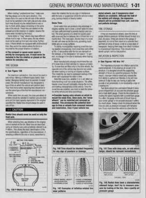 30
30 31
31 32
32 33
33 34
34 35
35 36
36 37
37 38
38 39
39 40
40 41
41 42
42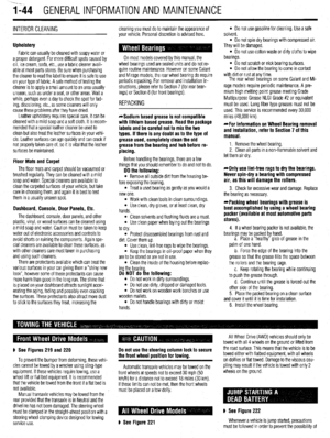 43
43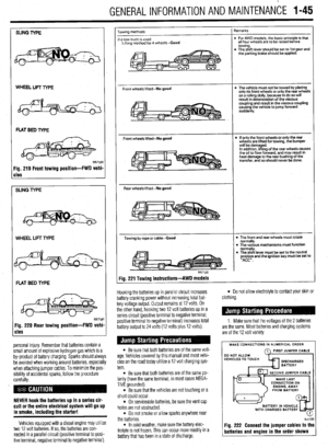 44
44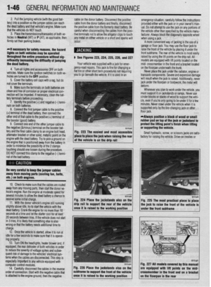 45
45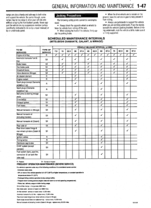 46
46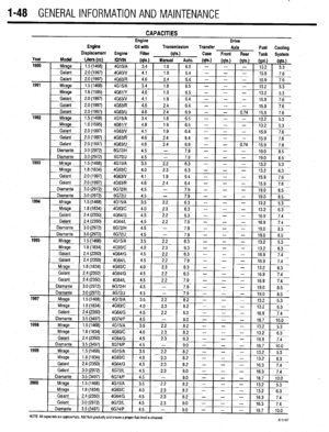 47
47 48
48 49
49 50
50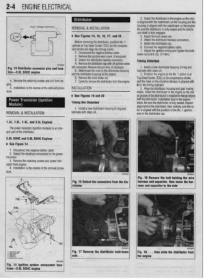 51
51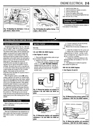 52
52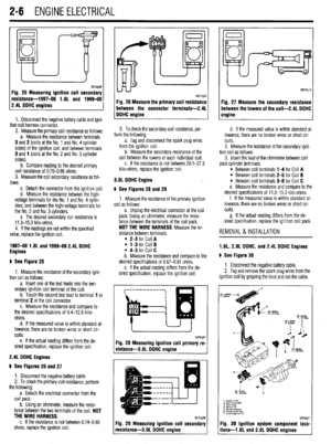 53
53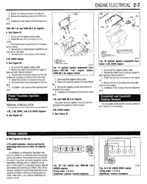 54
54 55
55 56
56 57
57 58
58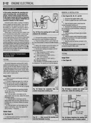 59
59 60
60 61
61 62
62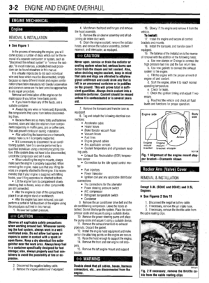 63
63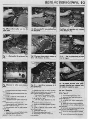 64
64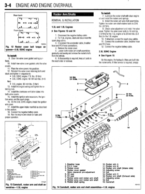 65
65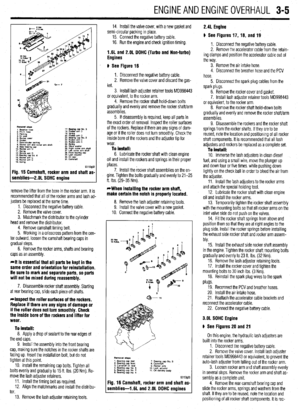 66
66 67
67 68
68 69
69 70
70 71
71 72
72 73
73 74
74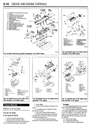 75
75 76
76 77
77 78
78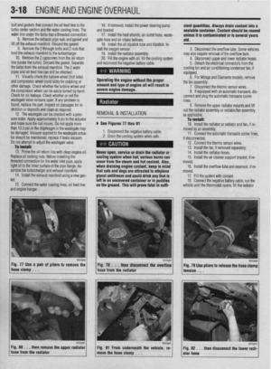 79
79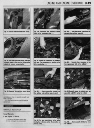 80
80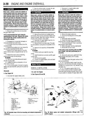 81
81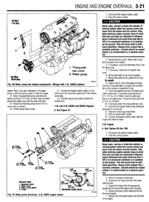 82
82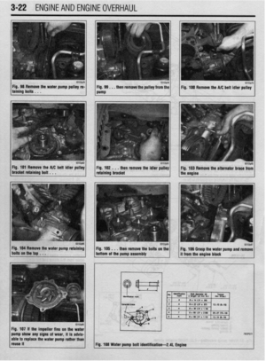 83
83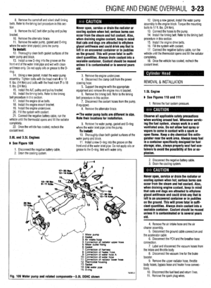 84
84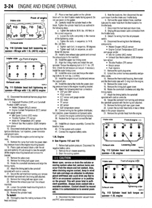 85
85 86
86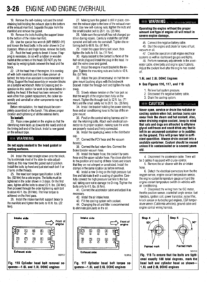 87
87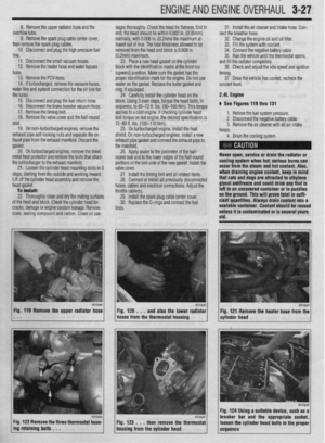 88
88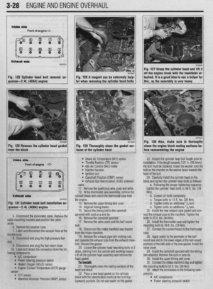 89
89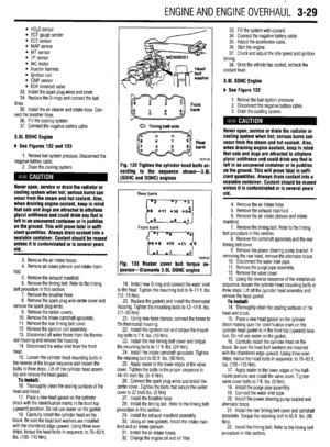 90
90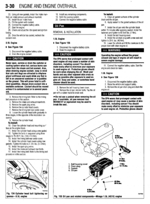 91
91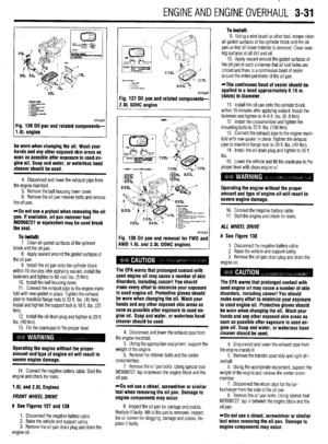 92
92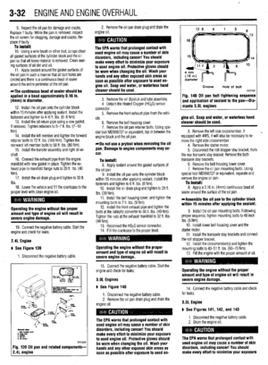 93
93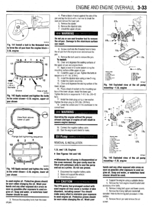 94
94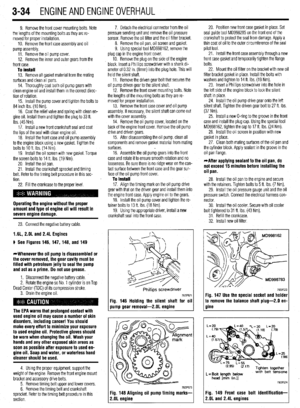 95
95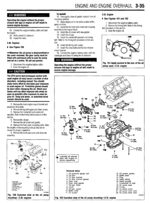 96
96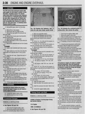 97
97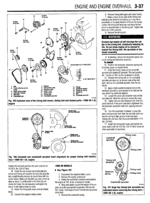 98
98 99
99 100
100 101
101 102
102 103
103 104
104 105
105 106
106 107
107 108
108 109
109 110
110 111
111 112
112 113
113 114
114 115
115 116
116 117
117 118
118 119
119 120
120 121
121 122
122 123
123 124
124 125
125 126
126 127
127 128
128 129
129 130
130 131
131 132
132 133
133 134
134 135
135 136
136 137
137 138
138 139
139 140
140 141
141 142
142 143
143 144
144 145
145 146
146 147
147 148
148 149
149 150
150 151
151 152
152 153
153 154
154 155
155 156
156 157
157 158
158 159
159 160
160 161
161 162
162 163
163 164
164 165
165 166
166 167
167 168
168 169
169 170
170 171
171 172
172 173
173 174
174 175
175 176
176 177
177 178
178 179
179 180
180 181
181 182
182 183
183 184
184 185
185 186
186 187
187 188
188 189
189 190
190 191
191 192
192 193
193 194
194 195
195 196
196 197
197 198
198 199
199 200
200 201
201 202
202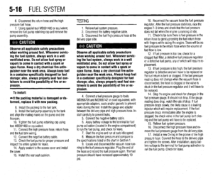 203
203 204
204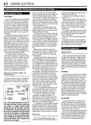 205
205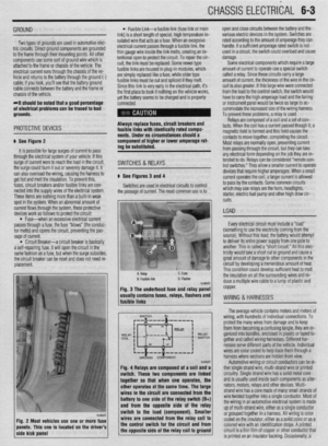 206
206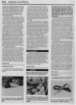 207
207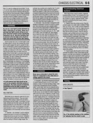 208
208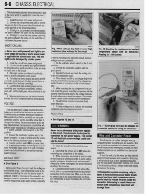 209
209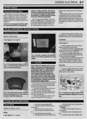 210
210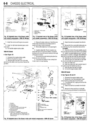 211
211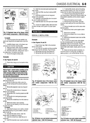 212
212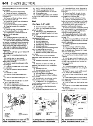 213
213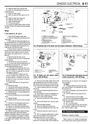 214
214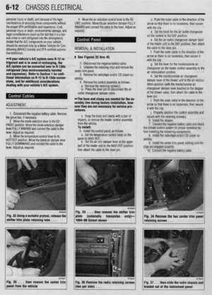 215
215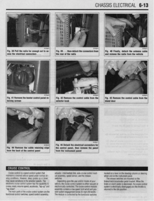 216
216 217
217 218
218 219
219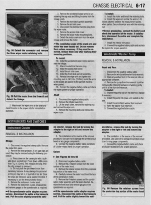 220
220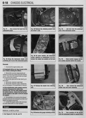 221
221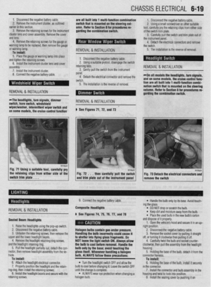 222
222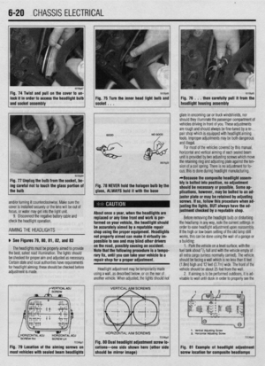 223
223 224
224 225
225 226
226 227
227 228
228 229
229 230
230 231
231 232
232 233
233 234
234 235
235 236
236 237
237 238
238 239
239 240
240 241
241 242
242 243
243 244
244 245
245 246
246 247
247 248
248 249
249 250
250 251
251 252
252 253
253 254
254 255
255 256
256 257
257 258
258 259
259 260
260 261
261 262
262 263
263 264
264 265
265 266
266 267
267 268
268 269
269 270
270 271
271 272
272 273
273 274
274 275
275 276
276 277
277 278
278 279
279 280
280 281
281 282
282 283
283 284
284 285
285 286
286 287
287 288
288 289
289 290
290 291
291 292
292 293
293 294
294 295
295 296
296 297
297 298
298 299
299 300
300 301
301 302
302 303
303 304
304 305
305 306
306 307
307 308
308 309
309 310
310 311
311 312
312 313
313 314
314 315
315 316
316 317
317 318
318 319
319 320
320 321
321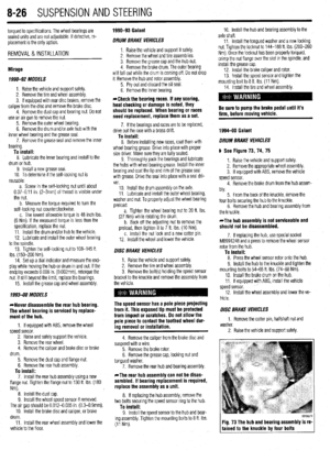 322
322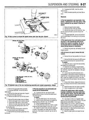 323
323 324
324 325
325 326
326 327
327 328
328 329
329 330
330 331
331 332
332 333
333 334
334 335
335 336
336 337
337 338
338 339
339 340
340 341
341 342
342 343
343 344
344 345
345 346
346 347
347 348
348 349
349 350
350 351
351 352
352 353
353 354
354 355
355 356
356 357
357 358
358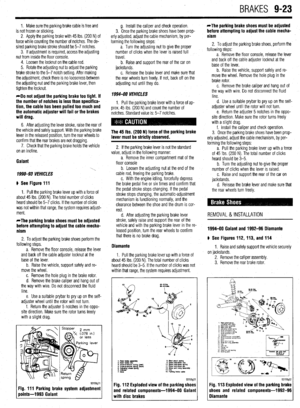 359
359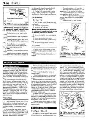 360
360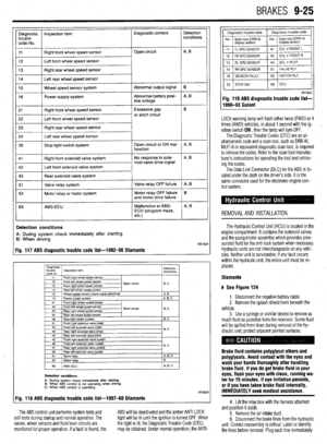 361
361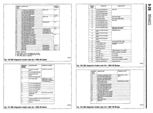 362
362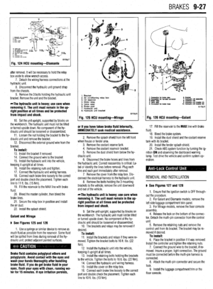 363
363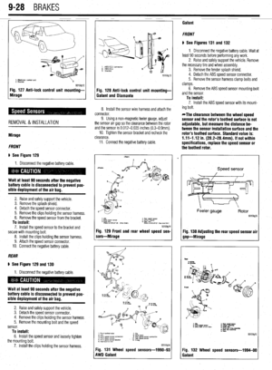 364
364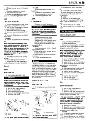 365
365 366
366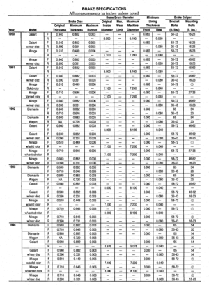 367
367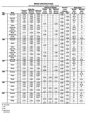 368
368 369
369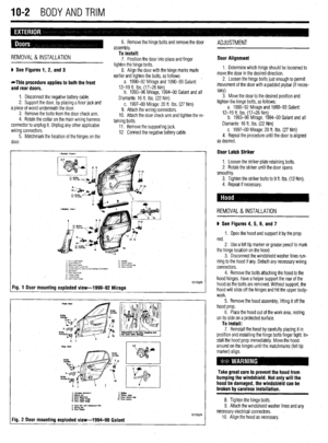 370
370 371
371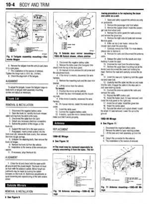 372
372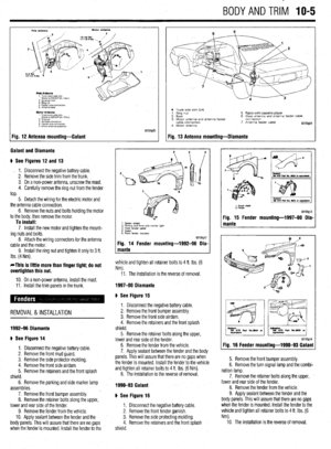 373
373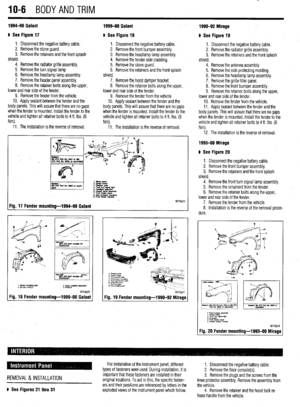 374
374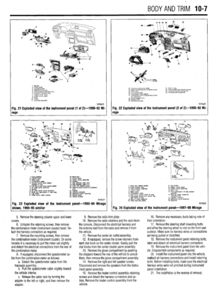 375
375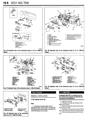 376
376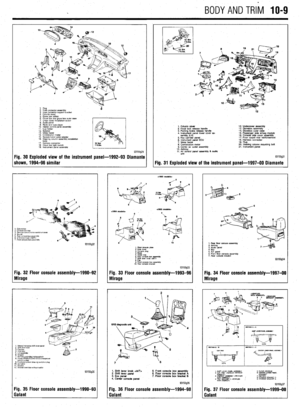 377
377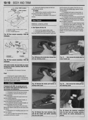 378
378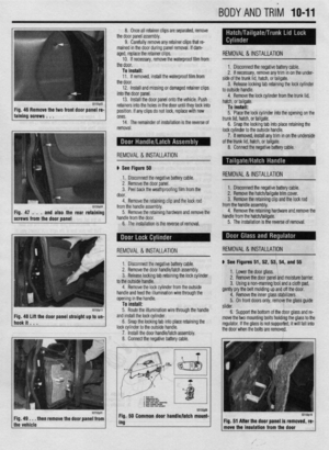 379
379 380
380 381
381 382
382 383
383 384
384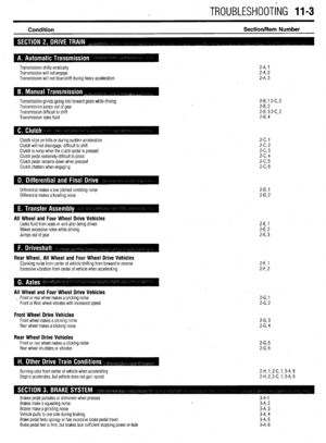 385
385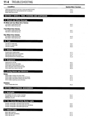 386
386 387
387 388
388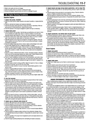 389
389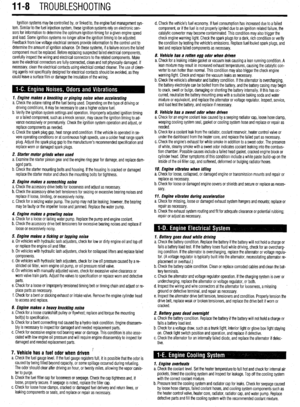 390
390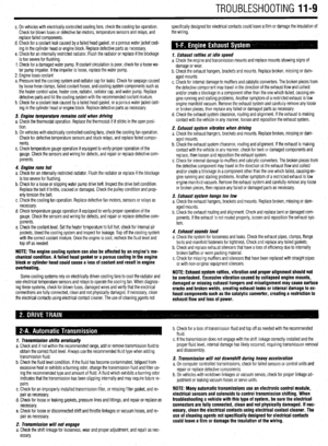 391
391 392
392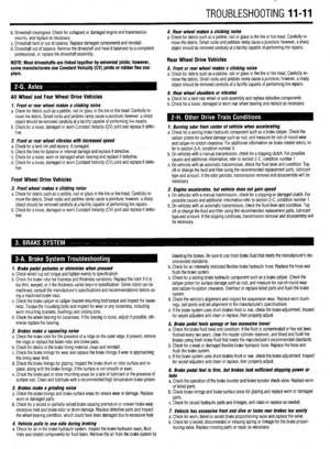 393
393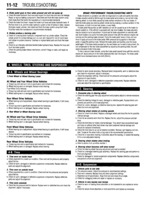 394
394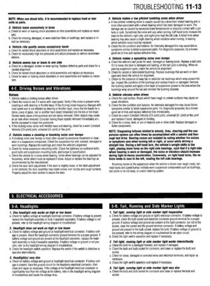 395
395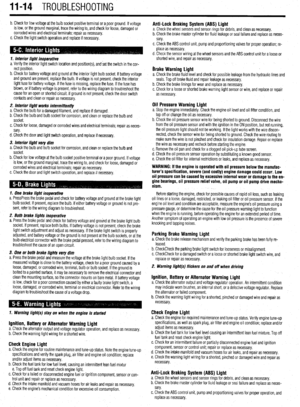 396
396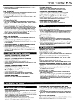 397
397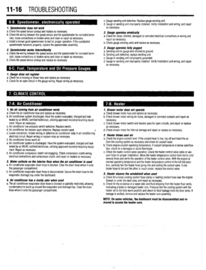 398
398 399
399 400
400 401
401 402
402 403
403 404
404 405
405 406
406 407
407