Page 145 of 408
 system. The PCV sys-
tem vents crankcase gases int")
4-2 DRIVEABILITYAND EMISSIONS CONTROLS
OPERATION
p See Figures 1, 2, and 3
All engines are equipped with the Positive
Crankcase Venhlation (PCV) system. The PCV sys-
tem vents crankcase gases into the engine air intake
where they are burned with the fuel and air mrxture.
The PCV system keeps pollutants from being re-
leased into the atmosphere It also helps to keep the
engine 011 clean, by ridding the crankcase of moisture
and corrosive fumes. The PCV system consists of the
PCV valve, the nipple in the air intake and the con-
necting hoses.
Incorrect operation of the PCV system can cause
multiple driveability symptoms.
A plugged valve or hose may cause’
l Rough Idle l Stalling or slow idle speed l Oil leaks
tT9574goi Fig. 1 Typical PCV system airflow
89574g0r5 Fig. 3 . . .
or mounted in a grommet on the
valve cover
l Sludge in en ine
A leakrng valve or ose would cause: i?
l Rough idle l Stalling l High idle speed
p See Figures 4 and 5
1. Disconnect the ventilation hose from the PCV
valve. Remove the PCV valve from the engine Once
removed, reconnect the ventilation hose to the valve.
2. Start the engine and allow to idle. Place a fin-
ger over open end of the PCV valve. Make sure intake
manifold vacuum is felt on finger.
3. If vacuum is not felt, the PCV valve may be re-
stricted.
4. Turn the engine
OFF and remove the PCV
valve from the hose.
5. Insert a thin stick into the threaded end of the
PCV valve. Push on the inner plunger and inspect for
movement.
6. If plunger inside the PCV valve is not free to
move back and forth, the valve is clogged and WIII re-
quire replacement.
*It is possible to clean the valve using the
appropriate solvent, but replacement is rec-
ommended.
REMOVAL&INSTALLATION
For PCV valve removal and installation, please re-
fer to Section 1 of this manual.
89574QO’ Fig. 4 With the engine idling, check the end
of the PCV valve to see if vacuum is present
Positive crankcase
ventilation
89574go6 Fig. 5 Inspect the PCV valve for inner
plunger movement. If the plunger is bound
or sticking, replace the valve OPERATION
p See Figures 6 and 7
Changes in atmospheric temperature cause fuel
tanks to breathe, that is, the air within the tank ex-
pands and contracts with outside temperature
changes. If an unsealed system was used, when the
temperature rises, air would escape through the tank
vent tube or the vent in the tank cap. The air which
escapes contains gasoline vapors.
The Evaporative Emission Control System pro-
vides a sealed fuel system with the capability to store
and condense fuel vapors. When the fuel evaporates
in the fuel tank, the vapor passes through the EVAP
emission valve, through vent hoses or tubes to a car-
bon filled evaporative canister. When the engine is
operahng the vapors are drawn into the intake mani-
fold and burned during combustion.
A sealed, maintenance free evaporative canister is
used The canister is filled wrth granules of an acti-
vated carbon mixture. Fuel vapors entering the canis-
ter are absorbed by the charcoal granules. A vent cap
is located on the top of the canister to provide fresh
air to the canister when it is being purged. The vent
cap opens to provide fresh air into the canister, which
circulates through the charcoal, releasing trapped va-
pors and carrying them to the engine to be burned.
Fuel tank pressure vents fuel vapors into the can-
ister. They are held in the canister until they can be
drawn into the intake manifold. The canister purge
valve allows the canister to be purged at a pre-deter-
mined time and engine operating conditions.
Vacuum to the canister is controlled by the canis-
ter purge valve. The valve IS operated by the PCM.
The PCM regulates the valve by switching the ground
circuit on and off based on engine operating condi-
tions When energized, the valve prevents vacuum
from reaching the canister. When not energized the
valve allows vacuum to purge the vapors from the
canister.
During warm up and for a specified time after hot
starts, the PCM energizes (grounds) the valve pre-
venting vacuum from reaching the canrster. When the
engine temperature reaches the operating level of
about 120°F (49°C) the PCM removes the ground
from the valve allowing vacuum to flow through the
canister and purges vapors through the throttle body.
During certain Idle conditions, the purge valve may
be grounded to control fuel mixture calibrations.
The fuel tank is sealed with a pressure-vacuum re-
lief filler cap. The relief valve in the cap is a safety
feature, preventing excessive pressure or vacuum in
the fuel tank. If the cap is malfunctioning, and needs
to be replaced, ensure that the replacement is the
identical cap to ensure correct system operation,
OBD-II EVAP System Monitor
Some models have added system components
due to the EVAP system monitor incorporated in the
OBD-II engrne control system. A pressure sensor is
mounted on the fuel tank which measures pressure
inside the tank, and a purge flow sensor measures
the flow of the gases from the canister into the en-
gine.
The PCM can store trouble codes for EVAP sys-
tem performance, a list of the codes is provided later
Page 146 of 408

DRIVEABILITYAND EMISSIONS CONTROLS 4-3
895?4Q3:
Fig. 6 Tvoical evaoorative emission control system schematic
EVAPORATIVE EMISSION CANISTER
Fig. 7 Evaporative emission canister com-
monly used on most models
in this section. Normal testing procedures can be
used, see EVAP System Component Testing in this
Section.
COMPONENTTESTING
89574g21 Fig. 8 To test the purge control operation,
connect the vacuum hose from the throttle
body to a vacuum pump
have elapsed after starting vehicle. Apply 14.8 in. Hg
of vacuum. The vacuum should be maintained mo-
mentarily, after which it should leak.
*The vacuum will leak continuously if the
altitude is 7,200 ft. or higher, or the intake
air temperature is 122°F (50°C) or higher.
Purge Control System Check
lB!M-93 VEHKLES EXCEPT 39911-92 2.UL
DDHC TURBO
p See Figure 8
1. Disconnect the red striped vacuum hose from
the throttle body and connect it to a hand held vac-
uum pump.
2. Plug the open nipple on the throttle body.
3. Using the hand pump, apply vacuum while the
engine is idling. Check that vacuum is maintained or
released as outlined below:
a. With the enaine coolant at 140°F f6O”C) or
less-14.8 in Hgof vacuum IS maintained. ’
b. With the coolant at 158°F (70°C) or
higher-14.8 in. Hg of vacuum is maintained.
4. With the engine coolant at 158°F (70°C) or
higher, run the engine at 3000 rpm within 3 minutes
of starting vehicle. Try to apply vacuum using the
hand held pump. Vacuum should leak.
5. With the engine coolant at 158°F (70°C) or
higher, run the engine at 3000 rpm after 3 minutes 6. If the test results differ from the desired results,
the purge control system is not operating properly.
199042 2.OL DDHC TURBO ENGINES
1, Disconnect the purge air hose from the intake
hose and plug the air intake hose.
2. Connect a hand vacuum pump to the purge air
hose.
3. Under various engine condrtions, inspect the
system operation:
a. Allow the engine to cool to a temperature
of 140°F (60°C) or below.
b. Start the engine and run at idle.
c. Using the hand pump, apply 14.8 in. Hg of
vacuum. In this condition, the vacuum should be
maintained.
d. Raise the engine speed to 3000 rpm.
e. Using the hand pump, apply 14.8 in. Hg of
vacuum. In this condition, the vacuum should be
maintained.
4. Run the engine until the coolant temperature
reaches 158°F (70°C). Inspect system operations as
follows: a. Using the hand pump, apply 14.8 in. Hg of
vacuum with the engine at idle. In this condition,
vacuum should be maintained.
b. Increase the enaine soeed to 3000 rpm
within 3 minutes of st&ting’the engine. Try ap-
plying vacuum. The vacuum should leak.
c. After 3 minutes have elapsed after starting
engine, raise the engine speed to 3000 rpm. Ap-
ply 14.8 in. Hg of vacuum. Vacuum should be
maintained momentarily, after which it will leak.
*The vacuum will leak continuously if the
altitude is 7200 ft. or higher or the air tem-
perature is 122°F (50°C) or higher.
5. If the results of either test differs from specifi-
cations, the system is not functioning
will require further diagnosis. properly and
1994-00 VEHICLES
p See Figure 9
*This test requires the use of a special
purge flow indicator tool, M8991700, or
equivalent.
1. Disconnect the purge hose from the EVAP can-
ister, then connect Purge Flow Indicator MB991700,
or equivalent between the canister and the purge
hose.
2. The engine should be warmed up to operating
temperature, 170-203°F. (80-95X), with all Irghts,
fans and accessories off. The transaxle should be in
Park for automatics or Neutral for manuals.
3. Run the engine at idle for at least 3-4 minutes.
4. Check the purge flow volume when the brake
is depressed suddenly a few times. The reading
should be 2.5 SCFH (20cmlsec.)
5. If the volume is less than the standard value,
check it again with the vacuum hose disconnected
from the canister. If the purge flow volume is less
than the standard, check for blockages in the vacuum
port and vacuum hose, and also inspect the evapora-
tive emission purge solenord and purge control
valve.
Page 147 of 408

4-4 DRIVEABILITYAND EMISSIONS CONTROLS
Fig. 10 Attach a hand vacuum pump to the
Ripple on the purge control valve
6. If the purge flow volume is at the standard
value, replace the EVAP canister.
Purge Control Valve
7990-93 2. OL TURBO ENGINE
u See Figure 10
1. The purge control valve is located to the right
side of the battery. Remove the purge control valve
from the engine compartment.
2. Connect a hand vacuum pump to the vacuum
nipple of the purge control valve.
3 Apply 15.7 in. Hg of vacuum and check air
tightness. Blow in air lightly from the evaporative
emission canister side nipple and check conditrons
as follows:
l If there is no vacuum applied to the
valve-air will not pass.
l When 8.0 in. Hg of vacuum is applied to
the valve-air will pass through.
4. Connect a hand vacuum pump to the positive
pressure nipple of the purge control valve.
5. Apply a vacuum of 15.7 in. HQ and check for
air tightness. The valve should be air tight.
6. If the results differ from the desired outcomes,
replace the purge control valve.
Evaporative Emission Purge Solenoid
1990-93 VEHICLES EXCEPT 1990-92 Z.OL
OOHC TURBO
p See Figures 11, 12, and 13
1. Label and disconnect the 2 vacuum hoses
from the purge control solenoid valve.
2. Detach the electrical harness connector from
the solenord.
3. Connect a hand vacuum pump to the nipple
which the red striped vacuum hose was connected.
4. Check air tightness by applying a vacuum with
voltage applied directly from the battery to the evapo-
rative emission purge solenoid and without applying
voltage. The desired results are as follows:
l With battery voltage applied-vacuum
should leak
l With battery voltage not applied-vacuum
should be maintained
5. Measure the resistance across the terminals of
the solenoid. The desired reading is 36-44 ohms
when at 68°F (20°C).
6. If any of the test results differ from the desired
outcomes, replace the purge control solenoid.
Fig. 11 Use a hand-held vacuum gauge to
check for air-tightness-1990-93 2.OL non-
turbo and 1993 2.OL turbo engines
8957dQ27 Fig. 12 Battery voltage applied to the ter-
minals of the evaporative emission purge
solenoid
89574Q28 1 Fig. 13 Measuring the resistance between
the terminals of the evaporative emission
/ purge solenoid
7990-92 2.OL OOHC TURBO ENGINE
1. Label and disconnect the 2 vacuum hoses
from the purge control solenoid valve.
2. Detach the electrical harness connector from
the solenoid.
3. Connect a hand vacuum pump to the nipple
which the red striped vacuum hose was connected.
4. Check air tightness by applying a vacuum with
voltage applied directly from the battery to the evapo-
rative emission purge solenoid and without applying
voltage. With battery voltage applied, vacuum should
be maintained. Without voltage, vacuum should leak
5. Measure the resistance across the terminals of
the solenoid. The desired reading is 36-44 ohms
when at 68°F (20°C).
6. If any of the test results differ from the specifi-
cations, replace the emission purge control solenoid.
Fig. 15 Measure the resistance across the
terminal of the solenoid valve-2.4L engine
shown, others similar
1994-00 VEHICLES
) See Figures 14 and 15
1. Tag and disconnect the vacuum hoses from
the solenoid valve.
2. Detach the harness connector.
3. Attach a hand-held vacuum pump to the nipple
(A) of the solenord valve, as shown in the accompa-
nying figures.
4. Check air tightness by applying a vacuum with
voltage applied directly from the battery to the evapo-
rative emission purge solenoid and without applying
voltage. The desired results are as follows:
l With battery voltage applied-vacuum
should be maintained
l With battery voltage not applied-vacuum
should leak
5. Measure the resistance across the terminals of
the solenoid. The standard values are as follows:
a. 25-44 ohms when at 68°F (20°C)
6. If any of the test results differ from the specifi-
cations, replace the emission purge control solenoid.
REMOVAL &INSTALLATION
EVAP Canister
p See Figure 16
1. Disconnect the negative battery cable.
2. If necessary, raise and safely support the vehi-
cle, remove the front passenger side wheel, then re-
move the splash shield.
3. Tag and disconnect all necessary vacuum
lines.
4. Unfasten and retaining bolts and/or straps,
then remove the canister from the vehicle
5. lnstallahon is the reverse of the removal proce-
dure.
Page 148 of 408

,
DRIVEABILITYAND EMISSIONS CONTROLS 4-5
Fig. 16 Remove the canister retaining bolts
and remove the canister
Solenoid Valves
u See Figures 17 and 18
1 b Disconnect the negative battery cable.
2. Label and remove the vacuum and electrical
harness connections from the purge control solenoid.
3. Remove the solenoid and mounting bracket
from the engine compartment.
4. Installation is the reverse of the removal proce-
dure.
I
- EVAPORATIVE EMISSION
Fig. 18 location of the evaporative emis-
purge solenoid-1990-93 2.OL DDHC
Volume air flow seneftr I
I Manifold diierential pressure m
&a$34
Fig. 19 Typical EGR system schematie-2.4L engine shown, others similar
IPERATION uum ports; pick one and plug the other. The vacuum
must be retained.
1 See Figure 19
The Exhaust Gas Recirculation (EM) system is
lesigned to reintroduce exhaust gas into the com-
ttii valve.
rustion chambers, thereby lowering combustion b. With 8.5 in. Hg (28.7 kPa) of vacuum or
emperatures and reducing the formation of Oxides of more applied to the valve, air should pass 4. For 1990-93 vehicles. blow air from 1 oas-
sage of the EGR to check condition as foffows--
a. With 1.8 in. Hg (6 kPa) of vacuum or less
aoolied to the valve. air should not oass throuah
litrogen (NO,).
The amount of exhaust gas that is reintroduced
Ito the combustion cycle is determined by several
actors, such as: engine speed, engine vacuum, ex-
raust system backpressure, coolant temperature,
Irottle position. All EGR valves are vacuum oper-
ted. The EGR vacuum diagram for your particular
chicle is displayed on the Vehicle Emission Control
iformation (VECI) label. through the valve.
5. For 1994-00 vehicles, apply vacuum (speci-
fied below) and check the passage of air by blowing
through either side of the EGR passages, as follows:
a. With 1 .?I in. Hg or less of vacuum applied
to the valve, air should blow out of the opposite
passa e.
b. %ith 8.7 in. Hg or more of vacuum applies
to the valve, air should not blow out of the oppo-
:OMPONENTTESTiNG site passage.
6. If the results are not as described, replace the
EGR valve.
iGR Valve
t See Figure 20
1. Remove the EGR valve from the vehicle. Check
I”..““.
:or sticking of plunger caused by excess carbon de-
losits. If such a condition exists, clean with appro- EGR Temperature Lan*nr
u See Figure 21
The EGR temperature sensor is used on California
vehicles only. The EGR temperature sensor detects
Fig. 20 Use a vacuum pump to test the EGR
I I
a coni tance i of water. then measure resis-
I ms the water temperature is increased
Page 149 of 408

the temperature of the gas passing through +h
control valve. It converts the detected temf
Ierature
into an electrical voltage signal which is sent the ve-
hicle’s Powertrain Control Module (PCM). If the cir-
cuit of the EGR temperature sensor is broken, the
warning light will come on.
1. Remove the EGR temperature sensor from the
engine.
2. Place the EGR sensor into water. While in-
creasing the temperature of the water, measure the
sensor resistance. Compare the values to following
specifications:
a. 122°F 50°C
b. 212°F 100” )-11-14 kohms resistance
t P O-83 kohms resistance
3. If the resistance obtained varies significantly ,
.,. . .
i, replace the sensor, nom specmcaoom
Thermal Vacuum Valva
therm0 valve.
2. Connect a hand held vacuum pump to the vac-
uum hose on the therm0 valve.
3. Apply vacuum and check the air passage
through the therm0 vOrL’n %ults to the fnrm
lowinq specifications:
ant temperature of 122°F
vacuum leaks
lant temoerature of 176’F 4 n;rm.nnnn+ +h.n s,r,,~,,,,rn hnm frnm ‘h.n +hrotle
body EGR vacuum nipple. Connect a hand-held
vac-
uum pump to the nipple.
2. Start the engine, then slowly raise the speed
and compare with the following specifications.
a. For 1990-93 vehides, check to be sure the
vacuum raised proportionally with the rise in en-
gine s eed.
b. Ior 199450 vehicles, the vacuum reading
on the pump should remain constant.
EGR Solenoid
1990-93 L’EHICL ES
# See Figures 24 and 25
1. Label and disconnect the yellow and green
striped vacuum hose from the EGR solenoid.
netted.
4. Apply vacuum and check for air-tightness
when voltage is applied and discontinued. When
voltage is applied, the vacuum should be maintained.
When voltage is discontinued, vacuum should leak.
5. Measure the resistance between the terminals
of the solenoid valve. The resistance should be
36-44 ohms at 68°F (20°C).
6. If the test results differ from the soecifications.
4-6 DRIVEABILITYAND EMISSIONSCONTROLS
Fig. 26 EGR solenoid
check connections-
# See Figure 22
1. Label and disconnect the vacuum hose at the 2. Detach the electrical harness connector.
3. Connect a hand vacuum pump to the nipple to
which the green-striped vacuum hose was con-
(80°C) 0; more-vacuum is maintained
4. If the results differ from the desired specifica-
tions, replace the valve.
EGR Port Vacuum Check
+ See Figure 23 replace the EGR solenoid.
1994-00 VEHICLES
# See Figure 26
*Before disconnecting the vacuum hoses,
tag them to assure proper connection during
. . ** *. 1. Tag and disconnect the vacuum hose (2.OL
turbo engine: yellow stripe, white and green stripe,
2.4L engine: yellow stripe and white stripe) from the
solenoid valve.
2. Detach the harness connector.
3. Connect a hand-held vacuum pump to the A
nipple.
4. Check air tightness by applying vacuum with
voltage applied directly from the battery to the EGR
control solenoid valve and without applying voltage.
5. For the 2.4L engines, compare with the follow-
ing:
. .
roltage not applied, vacuum a. With battery
should be maintainr
b. With battery
.I III I
snoura
iea~.
sd. -
/oltage applied, vacuum
6. Using an ohmmeter, measure the resistance
between the solenoid valve terminals. The resistance
should fall between 36-44 ohms when the enaine
temperature is 68°F (20°C).
REMOVAL&INSTALLATION
EGR Valve
iI See Figure 27 mslatlanon
1 I Disconnect the negative battery cable.
2. Remove the air cleaner and intake hoses as
required.
3. If necessary, detach the EGR temperature
sensor connector.
4. Tag and disconnect the vacuum hose from
the EGR valve.
5. Remove the mounting bolts and the EGR
2.OL engine (Federal) shown, others similar
valve from the engine.
Fig. 27 The EGR valve is retained to t
take manifold with two bolts-2.4L e
Page 150 of 408

.
DRIVEABILITYAND EMISSIONS CONTROLS 4-7
6. Clean the mating surfaces on the valve and
the engine. Make sure to remove all gasket material.
7. Inspect the valve for a sticking plunger,
caused by excess carbon deposits. If such a condi-
tion exists, clean with appropriate solvent so valve
seats correctly.
To install:
8. Install EGR valve with a new gasket in place.
9. Install the mounting bolts and tighten as fol- EGR Solenoid
e See Figures 28, 29, 39, 31, and 32
1. Disconnect the negative battery cable.
2. Label and disconnect the vacuum hoses from
the EGR solenoid.
3. Disconnect the electrical harness from the so-
lenoid.
4. Remove the solenoid from the mountino
lows: * 1.5L, 1.6L, and 1.81 engines-7-10 ft.
Ibs. (IO-15 Nm)
l 2.OL engines-IO-15 ft. Ibs. (15-22
NW
l 2.4L and 3.5L engines-16 ft. Ibs. (22
NW
l 3.01 engines-8 ft. Ibs. (11 Nm)
10. Connect the vacuum hose to the EGR valve.
11. If detached, attach the EGR temperature sen- -
bracket and replace as required.
To install:
5. Install the solenoid to the mounting bracket
and secure in position.
6. Attach the electrical connector.
7. Connect the vacuum hoses to the solenoid
making sure they are installed in their original loca-
tion.
8. Connect the negative battery cable.
sor.
12. Install the air cleaner and air intake hoses as
I
required.
13. Connect the negative battery cable.
EGR Temperature Sensor
1. Disconnect the negative battery cable.
2. Detach the electrical connector from the sen-
sor.
3. Remove the sensor from the engine.
To install:
4. Install the sensor to the engine and tighten to 8
ft. Ibs. (12 Nm).
5. Attach the electrical connector to the sensor.
6. Connect the negative battery cable.
Thermal Vacuum Valve
1. Disconnect the negative battery cable. Fig. 28 Location of the EGR solenoid-2.41
Galant shown
valve.
7. Attach the vacuum hose to the valve 1 bracket 6. Tighten the valve to l‘j30 ft. Ibs. (20-40
91054p19
Nm). When installing the valve, do not allow the Fig. 29 Release the retaining tab and re-
wrench to come in contact with the resin part of the move the solenoid from the retaining Fig, 30 Matchmark the hoses on the sole-
noid . . .
8. Connect the negative battery cable.
Page 151 of 408
 See Figure 33
*The Powertrain Control Module (PCM) is
located above the passeng")
.
4-8 DRIVEABILITYAND EMISSIONS CONTROLS
93154g17 Fig. 33 PCM mounting location-Mirage
Mirage and 1999-00 Galant
) See Figure 33
*The Powertrain Control Module (PCM) is
located above the passenger side kickpanel.
1. Disconnect the negative battery cable.
2. Remove the @love box, right side kickpanel
and lower panel assemblies.
3. Unplug the connectors and remove fasteners.
Remove the PCM.
4. Installation is the reverse of the removal proce-
dure.
1994-98 Galant
+ See Figure 34
1, Disconnect negative battery cable.
2. Remove both center console side panels.
3. Unplug the wiring connector and remove the
mounting hardware. Slide the PCM out the side.
4. installation is the reverse of the removal proce-
dure.
Diamante and 1990-93 Galant
) See Figures 35 and 38
*The Powertrain Control Module (PCM) is
located behind the glove box assembly.
1, If equipped, disarm the air bag system
2. Remove the passenger side lower instrument
panel and shower duct.
3. Remove the glove box striker, glove box, glove
box outer casing and the screw below the assembly.
4. Unplug wiring connector and remove mount-
ing hardware. Slide out the PCM.
To install: 5. Install the PCM with the mounting hardware.
6. Attach the wire connector.
7. Install the glove box striker, the glove box, the
glove box casing and the screw below the assembly.
Q3154g15 Fig. 35 PCM mounting location-1990-93
Galant
93154g16 Fig. 38 PCM mounting location-Diamante
8. Install the passenger side lower instrument
panel and the shower duct.
9. Reconnect the negative battery cable
OPERATION
The Oxygen (02) sensor is a device which pro-
duces an electrical voltage when exposed to the oxy-
gen present in the exhaust gases. The sensor is
mounted in the exhaust system, usually in the mani-
fold or a boss located on the down pipe before the
catalyst. The oxygen sensors used on some models
are electrically heated internally for faster switching
when the engine is started cold. The oxygen sensor
produces a voltage within 0 and 1 volt. When there is
a large amount of oxygen present (lean mixture), the
sensor produces a low voltage (less than 0.4~). When
there is a lesser amount present (rich mixture) it pro-
duces a higher voltage (0.6-I .Ov). The stoichiometric
or correct fuel to air ratio will read between 0.4 and
0.6~. By monitoring the oxygen content and convert-
ing it to electrical voltage, the sensor acts as a rich-
lean switch. The voltage is transmitted to the PCM.
Some models have two sensors, one before the
catalyst and one after. This is done for a catalyst eff i-
ciency monitor that is a part of the OBD-II engine
controls. The one before the catalyst measures the
exhaust emissions right out of the engine, and sends
the signal to the PCM about the state of the mixture
as previously talked about. The second sensor re-
ports the difference in the emissions after the exhaust
gases have gone through the catalyst. This sensor re-
ports to the PCM the amount of emissions reduction
the catalyst is performing.
The oxygen sensor will not work until a predeter-
mined temperature is reached, until this time the
PCM is running in what as known as OPEN LOOP
operation. OPEN LOOP means that the PCM has not
yet begun to correct the air-to-fuel ratio by reading the oxygen sensor. After the engine comes to operat-
ing temperature, the PCM will monitor the oxygen
sensor and correct the air/fuel ratio from the sensor’s
readings. This is what is known as CLOSED LOOP
operation.
A Heated Oxygen Sensor (H02S) has a heating el-
ement that keeps the sensor at proper operatmg tem-
perature during all operating modes. Maintaining
correct sensor temperature at all times allows the
system to enter into CLOSED LOOP operation
sooner.
In CLOSED LOOP operation, the PCM monitors
the sensor input (along with other inputs) and adjusts
the injector pulse width accordingly. During OPEN
LOOP operation, the PCM ignores the sensor input
and adjusts the injector pulse to a preprogrammed
value based on other inputs.
TESTING
# See Figure 37
93154p36 Fig. 37 The HD2S can be monitored with an
appropriate and Data-stream capable scan
tool
Do not pierce the wires when testing this
sensor; this can lead to wiring harness dam-
age. Backprobe the connector to properly
read the voltage of the HD2S.
1. Disconnect the H02S.
2. Measure the resistance between PWR and
GND terminals of the sensor. Resistance should be
approximately 6 ohms at 68°F (20°C) If resistance is
not within specification, the sensor’s heater element
is faulty.
3. With the H02S connected and engine running,
measure the voltage with a Digital Volt-Ohmmeter
(DVOM) between terminals
HD2S and SIG RTN (GND) of the oxygen sensor connector. Voltage
should fluctuate between 0.01-l .O volts. If voltage
fluctuation is slow or voltage is not within specifica-
tion, the sensor may be faulty.
REMOVAL &INSTALLATION
) See Figures 38, 39, 40, 41, and 42
1. Disconnect the negative battery cable
2. Raise and support the vehicle safely.
Page 152 of 408

DRIVEABILITYAND EMISSIOP JSCONTRiLS 4-9
3. Label and disconnect the H02S from the en-
gine control wiring harness.
*Lubricate the sensor with penetrating oil
prior to removal.
4. Remove the sensor using an oxygen sensor
I To install: - -v- -- ---- ..----. ----...= -..- r... *-
5. Install the sensor in the mounting boss and
hl-li)r\,,.l 0 ,.l.-.f.l, .T‘fi.LI wrench or another suitable tool.
tighten to 27-33 ft. Ibs. (37-45 Nm).
6. Connect the engine control wiring harness to 1 Fia. 43 IAC mntnr tnfitinn and nin Incations 1
KtMUVHL i% IN3 I ALLA I IUN
See Fiaurr! d4
1. Disconnect the negative battery cable.
2. Remove the air cleaner intake hose.
move the oxygen sensor. The socket con- 3. Remove any necessary hoses from the IAC
OPERATION
The Idle Air Control (IAC) motor is a DC stepper
motor controlled by the PCM. The IAC contains a
built-in position sensor which detects the amount of
opening of the motor. The position sensor outputs a
pulse signal that the PCM receives and uses to adjust
the motor to properly maintain the correct idle speed
of the engine. motor.
5. Remove the retainino bolts and remove the IAC
y -_.._ -..- ._... -._ . .._ ._ from the throttle body. C The inc.hllrrti~n a 11o IIIJL(IIIoLIuII is the reverse of removal. Re-
plaie the IAC gasket.
TESTING
I
ti See Figure 43
Place a stethoscope (a long screwdriver works
also, just place the screwdriver on the IAC and place
your ear on or near the handle) on the IAC motor.
Have an assistant turn the key ON with the engine
OFF, and listen to the IAC motor. Several clicks
should be heard as the steooer motor moves. If the
clicks are heard, the driver in the PCM and the circuit
are OK.
If the driver and circuits test OK, detach the con-
nectar from IAC motor. Using an ohmmeter, probe ‘. l-!AEz?rn~ -w
2 Idle an conh0l motor nswltch)
the connector on the IAC motor, NOT THE WIRING
HARNESS> between pins 2 and 1, and pins 2 and 3.
Resistance should measure between 26-33 ohms. If
the resistance values are different replace the IAC tor is usually mounted
motor. If the tests between pins 1,2, and 3 are within
specification, check the resistance between pins 5
and 4, and pins 5 and 6. Resistance should measure
between 26-33 ohms. If the resistance values are dif-
then remove the sensor from ferent replace the IAC motor.
 1
1 2
2 3
3 4
4 5
5 6
6 7
7 8
8 9
9 10
10 11
11 12
12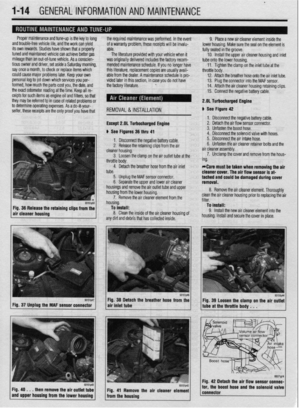 13
13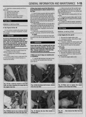 14
14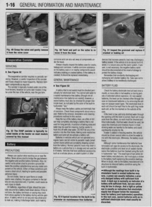 15
15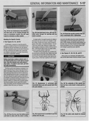 16
16 17
17 18
18 19
19 20
20 21
21 22
22 23
23 24
24 25
25 26
26 27
27 28
28 29
29 30
30 31
31 32
32 33
33 34
34 35
35 36
36 37
37 38
38 39
39 40
40 41
41 42
42 43
43 44
44 45
45 46
46 47
47 48
48 49
49 50
50 51
51 52
52 53
53 54
54 55
55 56
56 57
57 58
58 59
59 60
60 61
61 62
62 63
63 64
64 65
65 66
66 67
67 68
68 69
69 70
70 71
71 72
72 73
73 74
74 75
75 76
76 77
77 78
78 79
79 80
80 81
81 82
82 83
83 84
84 85
85 86
86 87
87 88
88 89
89 90
90 91
91 92
92 93
93 94
94 95
95 96
96 97
97 98
98 99
99 100
100 101
101 102
102 103
103 104
104 105
105 106
106 107
107 108
108 109
109 110
110 111
111 112
112 113
113 114
114 115
115 116
116 117
117 118
118 119
119 120
120 121
121 122
122 123
123 124
124 125
125 126
126 127
127 128
128 129
129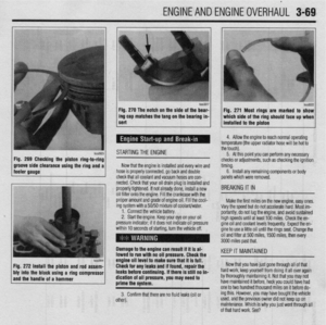 130
130 131
131 132
132 133
133 134
134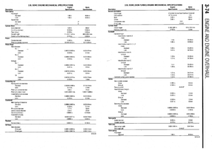 135
135 136
136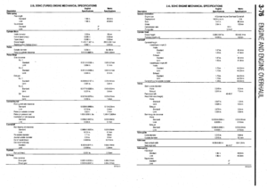 137
137 138
138 139
139 140
140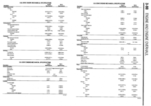 141
141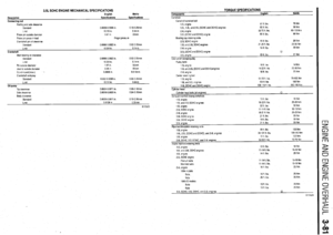 142
142 143
143 144
144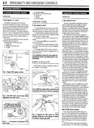 145
145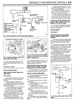 146
146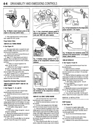 147
147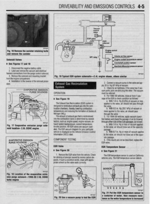 148
148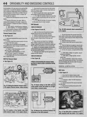 149
149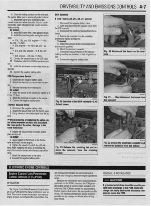 150
150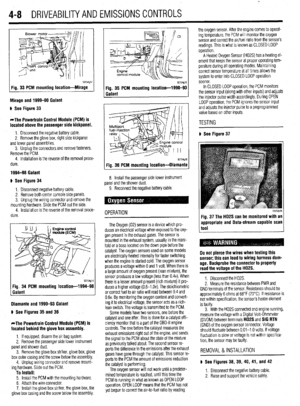 151
151 152
152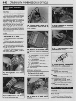 153
153 154
154 155
155 156
156 157
157 158
158 159
159 160
160 161
161 162
162 163
163 164
164 165
165 166
166 167
167 168
168 169
169 170
170 171
171 172
172 173
173 174
174 175
175 176
176 177
177 178
178 179
179 180
180 181
181 182
182 183
183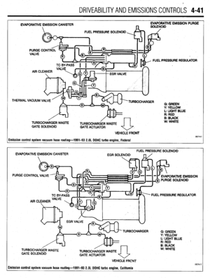 184
184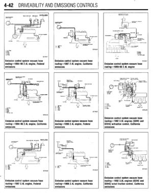 185
185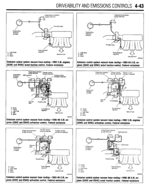 186
186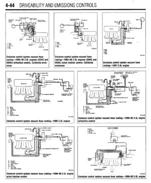 187
187 188
188 189
189 190
190 191
191 192
192 193
193 194
194 195
195 196
196 197
197 198
198 199
199 200
200 201
201 202
202 203
203 204
204 205
205 206
206 207
207 208
208 209
209 210
210 211
211 212
212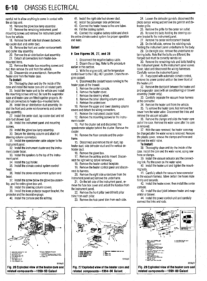 213
213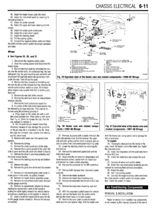 214
214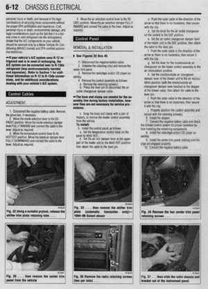 215
215 216
216 217
217 218
218 219
219 220
220 221
221 222
222 223
223 224
224 225
225 226
226 227
227 228
228 229
229 230
230 231
231 232
232 233
233 234
234 235
235 236
236 237
237 238
238 239
239 240
240 241
241 242
242 243
243 244
244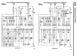 245
245 246
246 247
247 248
248 249
249 250
250 251
251 252
252 253
253 254
254 255
255 256
256 257
257 258
258 259
259 260
260 261
261 262
262 263
263 264
264 265
265 266
266 267
267 268
268 269
269 270
270 271
271 272
272 273
273 274
274 275
275 276
276 277
277 278
278 279
279 280
280 281
281 282
282 283
283 284
284 285
285 286
286 287
287 288
288 289
289 290
290 291
291 292
292 293
293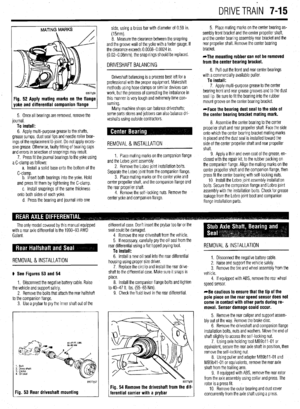 294
294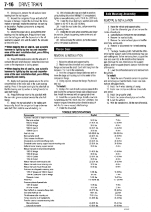 295
295 296
296 297
297 298
298 299
299 300
300 301
301 302
302 303
303 304
304 305
305 306
306 307
307 308
308 309
309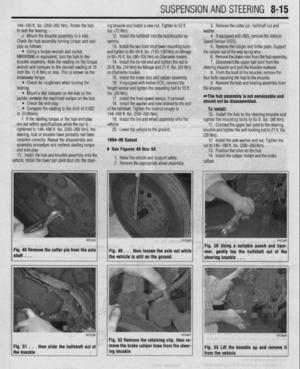 310
310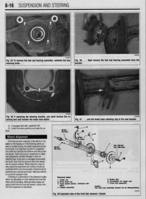 311
311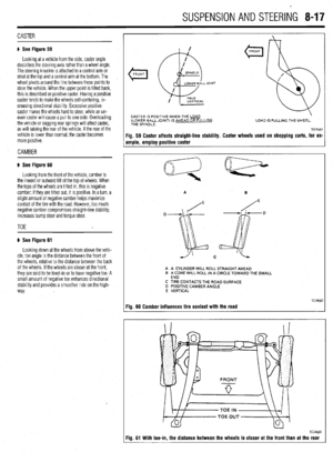 312
312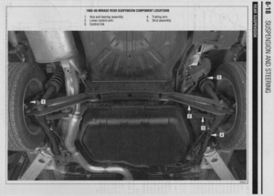 313
313 314
314 315
315 316
316 317
317 318
318 319
319 320
320 321
321 322
322 323
323 324
324 325
325 326
326 327
327 328
328 329
329 330
330 331
331 332
332 333
333 334
334 335
335 336
336 337
337 338
338 339
339 340
340 341
341 342
342 343
343 344
344 345
345 346
346 347
347 348
348 349
349 350
350 351
351 352
352 353
353 354
354 355
355 356
356 357
357 358
358 359
359 360
360 361
361 362
362 363
363 364
364 365
365 366
366 367
367 368
368 369
369 370
370 371
371 372
372 373
373 374
374 375
375 376
376 377
377 378
378 379
379 380
380 381
381 382
382 383
383 384
384 385
385 386
386 387
387 388
388 389
389 390
390 391
391 392
392 393
393 394
394 395
395 396
396 397
397 398
398 399
399 400
400 401
401 402
402 403
403 404
404 405
405 406
406 407
407