Page 289 of 360

JACKING AND TIRE
CHANGINGWARNING!
Do not attempt to change a tire onthe side of the vehicle close to
moving traffic. Pull far enough
off the road to avoid the danger of
being hit when operating the jack
or changing the wheel.
Being under a jacked-up vehicle is dangerous. The vehicle could
slip off the jack and fall on you.
You could be crushed. Never put
any part of your body under a
vehicle that is on a jack. If you
need to get under a raised vehicle,
take it to a service center where it
can be raised on a lift.
Never start or run the engine while the vehicle is on a jack.
The jack is designed to be used as a tool for changing tires only. The
jack should not be used to lift the
vehicle for service purposes. The
vehicle should be jacked on a firm
level surface only. Avoid ice or
slippery areas. JACK LOCATION
The jack, jack handle and winch
handle tools are stowed behind the
rear left side trim panel in the rear
cargo area. Turn the two cover latches
to release the cover.
Remove the pouch containing the
scissors jack, jack handle, and tools.
SPARE TIRE REMOVAL
The spare tire is stowed inside a pro-
tective cover located under the center
of the vehicle between the front doors
by means of a cable winch mecha-
nism. The “spare tire drive” nut is
located on the floor, under a plastic
cap at the front of the floor console or
under front super console forward bin
liner.
TO ACCESS SPARE TIRE
WINCH DRIVE NUT
To access the spare tire winch drive
nut and lower the spare tire, you will
need to refer to one of the following
center console configurations.
Jack And Tool Location
Spare Tire Location
283
Page 290 of 360

Super Console
For vehicles equipped with the Super
Console, the spare tire winch assem-
bly drive nut is located beneath the
console.
1. Pull the lower drawer out from the
rear of the floor console to gain clear
access of the tire winch drive nut.
2. Open the front drawer to expose
the storage compartment.
3. Remove the liner from the con-
sole's storage compartment to access
the spare tire winch drive nut.Premium/Base/Cargo Center
Console
Pull the Winch Cover assembly plug
(for versions/markets, where pro-
vided) to access the winch drive nut.
SPARE TIRE TOOLS
The tool pouch contains three pieces
and can be assembled into a spare tire
hook; to remove the compact spare tire/
cover assembly from under the vehicle,
or a Winch T-handle; to raise/lower the
compact spare tire/cover assembly.
Super Console
1 — Lower Drawer
2 — Front Drawer
3 — Front Drawer Liner
Drive Nut Access
Winch Cover Assembly Plug
(If Equipped)
Assembled T-handle
A — Spare Tire Hook/T-handle
B — Extension 1
C — Extension 2
284
Page 291 of 360

SPARE TIRE REMOVAL
INSTRUCTIONS
The spare tire is located under the
vehicle beneath the center console
area.1. Assemble the spare tire tools into a
T-handle and place the square end
over the spare tire winch drive nut.
2. Rotate the nut to the left until the
winch mechanism stops turning
freely. This will allow enough slack in
the cable to allow you to pull the spare
tire out from underneath the vehicle.
CAUTION!
The winch mechanism is designed
for use with the winch T-handle
only. Use of an air wrench or other
power tools is not recommended
and can damage the winch.
3. To remove the compact spare tire/
cover assembly, assemble the winch
T-handle extensions to form a spare
tire hook, and pull the spare tire out
from under the vehicle. NOTE: If either front tire is flat it
may be necessary to jack up the
vehicle to remove the compact
spare tire/cover assembly from
under the vehicle.
4. Stand the tire/cover assembly up-
right and remove the wheel spacer by
squeezing the winch retaining tabs to-
gether. Push the retainer through the
spare tire to release it from the wheel.
Assembling The Spare Tire Hook
A — Spare Tire Hook/T-handle
B — Extension 1
C — Extension 2
Spare Tire And Cover
Pulling Spare Tire
Removing Wheel Spacer
285
Page 292 of 360

PREPARATIONS FOR
JACKING
1. Park the vehicle on a firm, level
surface. Avoid ice or slippery areas.WARNING!
Do not attempt to change a tire on
the side of the vehicle close to mov-
ing traffic, pull far enough off the
road to avoid being hit when oper-
ating the jack or changing the
wheel.
2. Turn on the Hazard Warning
flasher.
3. Set the parking brake.
4. Place the shift lever into PARK.
5. Turn OFF the ignition. 6. Block both the
front and rear of
the wheel diago-
nally opposite the
jacking position.
For example, if
changing the right
front tire, block the left rear wheel. NOTE: Passengers should not
remain in the vehicle when the ve-
hicle is being jacked.
JACKING INSTRUCTIONS
WARNING!
Carefully follow these tire changing
warnings to help prevent personal
injury or damage to your vehicle:
Always park on a firm, level sur-
face as far from the edge of the
roadway as possible before rais-
ing the vehicle.
Turn on the Hazard Warning
flasher.
Block the wheel diagonally oppo- site the wheel to be raised.
Set the parking brake firmly and
set an automatic transmission in
PARK; a manual transmission in
REVERSE.
Never start or run the engine with
the vehicle on a jack.
Do not let anyone sit in the vehicle when it is on a jack.
(Continued)
WARNING!(Continued)
Do not get under the vehicle when it is on a jack. If you need to get
under a raised vehicle, take it to a
service center where it can be
raised on a lift.
Only use the jack in the positions indicated and for lifting this ve-
hicle during a tire change.
If working on or near a roadway,
be extremely careful of motor
traffic.
To assure that spare tires, flat or
inflated, are securely stowed,
spares must be stowed with the
valve stem facing the ground.CAUTION!
Do not attempt to raise the vehicle
by jacking on locations other than
those indicated in the Jacking In-
structions for this vehicle.
Jack Warning Label
286
Page 293 of 360

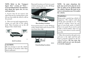
NOTE: Refer to the “Compact
Spare Tire” section of “Tires –
General Information” for informa-
tion about the spare tire, its use,
and operation.
1. Loosen (but do not remove) the
wheel lug nuts by turning them to the
left one turn while the wheel is still on
the ground.
2. There are two jack engagement lo-
cations on each side of the vehicle
body. These locations are on the sill
flange of the vehicle body.CAUTION!
Do not attempt to raise the vehicle
by jacking on locations other than
those indicated.Rear jack locations are between a pair
of down-facing tabs on the sill flange
of the vehicle side body.
Front jack location is on the sill flange
of the vehicle body and is located 150
mm from door edge.
NOTE: In some situations the
jack may need to be placed on its
side in order to be pushed under
the vehicle. Return the jack to its
correct orientation once it is under
the vehicle.
WARNING!
Being under a jacked-up vehicle is
dangerous. The vehicle could slip
off the jack and fall on you. You
could be crushed. Never get any
part of your body under a vehicle
that is on a jack. If you need to get
under a raised vehicle, take it to a
service center where it can be raised
on a lift.
3. Place the wrench on the jack screw
and turn to the right until the jack
head is properly engaged in the de-
scribed location. Do not raise the
vehicle until you are sure the jack
is securely engaged.
Jack Locations
Rear Jacking LocationsFront Jacking Locations
287
Page 294 of 360

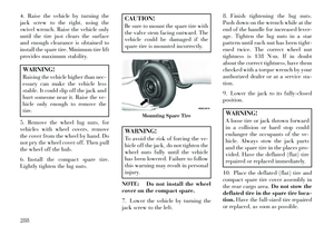
4. Raise the vehicle by turning the
jack screw to the right, using the
swivel wrench. Raise the vehicle only
until the tire just clears the surface
and enough clearance is obtained to
install the spare tire. Minimum tire lift
provides maximum stability.WARNING!
Raising the vehicle higher than nec-
essary can make the vehicle less
stable. It could slip off the jack and
hurt someone near it. Raise the ve-
hicle only enough to remove the
tire.
5. Remove the wheel lug nuts, for
vehicles with wheel covers, remove
the cover from the wheel by hand. Do
not pry the wheel cover off. Then pull
the wheel off the hub.
6. Install the compact spare tire.
Lightly tighten the lug nuts.
CAUTION!
Be sure to mount the spare tire with
the valve stem facing outward. The
vehicle could be damaged if the
spare tire is mounted incorrectly.WARNING!
To avoid the risk of forcing the ve-
hicle off the jack, do not tighten the
wheel nuts fully until the vehicle
has been lowered. Failure to follow
this warning may result in personal
injury.
NOTE: Do not install the wheel
cover on the compact spare.
7. Lower the vehicle by turning the
jack screw to the left. 8. Finish tightening the lug nuts.
Push down on the wrench while at the
end of the handle for increased lever-
age. Tighten the lug nuts in a star
pattern until each nut has been tight-
ened twice. The correct wheel nut
tightness is 138 N·m. If in doubt
about the correct tightness, have them
checked with a torque wrench by your
authorized dealer or at a service sta-
tion.
9. Lower the jack to its fully-closed
position.
WARNING!
A loose tire or jack thrown forward
in a collision or hard stop could
endanger the occupants of the ve-
hicle. Always stow the jack parts
and the spare tire in the places pro-
vided. Have the deflated (flat) tire
repaired or replaced immediately.
10. Place the deflated (flat) tire and
compact spare tire cover assembly in
the rear cargo area. Do not stow the
deflated tire in the spare tire loca-
tion. Have the full-sized tire repaired
or replaced, as soon as possible.
Mounting Spare Tire
288
Page 295 of 360

11. Stow the cable and wheel spacer
before driving the vehicle. Reas-
semble the winch handle extensions to
form a “T” and fit the winch T-handle
over the drive nut. Rotate the nut to
the right until the winch mechanism
clicks at least three times.
NOTE: Refer to the “Spare Tire
Tools” section for instructions on
assembling the T-handle.
12. Stow the jack, jack handle and
winch handle tools back in the stow-
age compartment.
13. Check the compact spare tire
pressure as soon as possible. Correct
the tire pressure, as required.
SECURING THE SPARE
TIRE
1. Assemble the winch handle exten-
sions to form a T-handle and fit the
winch T-handle over the drive nut.
Rotate the nut to the left until the
winch mechanism stops turning
freely. This will allow enough slack in
the cable to allow you to pull the
wheel spacer out from under the ve-
hicle.
WARNING!
A loose compact spare tire/cover
assembly, thrown forward in a col-
lision or hard stop could endanger
the occupants of the vehicle. Al-
ways stow the compact spare tire
with the cover assembly in the place
provided.CAUTION!
The winch mechanism is designed
for use with the winch T-handle
only. Use of an air wrench or other
power tools is not recommended
and can damage the winch.
2. Assemble the winch handle exten-
sions to form the spare tire hook, and
pull the wheel spacer from under the
vehicle.
3. Turn the compact spare tire so that
the valve stem is down, and place the
tire into the spare tire/cover assembly.
Slide the wheel spacer through the
center of the wheel and spare tire/
cover assembly, so that the two re-
tainer tabs snap out and engage the
spare tire cover on the opposite side.
CAUTION!
The compact spare tire/cover as-
sembly must be used when the
compact spare tire is stored. Failure
to use this cover could drastically
reduce the life of the compact spare
tire.WARNING!
Verify that both retainer tabs of the
wheel spacer have been properly
extended through the center of the
wheel and spare tire/cover assem-
bly. Failure to properly engage both
retainer tabs could result in loss of
the spare tire and cover assembly,
which will cause vehicle damage
and may cause loss of vehicle con-
trol.
4. Using the winch T-handle, rotate
the drive nut to the right until the
compact spare tire/cover assembly is
drawn into place against the under-
side of the vehicle.
289
Page 296 of 360

5. Continue to rotate the nut to the
right until you hear the winch mecha-
nism click three times. It cannot be
overtightened. Check under the ve-
hicle to ensure the compact spare tire/
cover assembly is positioned correctly
against the underside of the vehicle.CAUTION!
The winch mechanism is designed
specifically to stow a compact spare
tire only. Do not attempt to use the
winch to stow the full size flat tire,
or any other full-size tire. Vehicle
damage may result.
ROAD TIRE
INSTALLATION
Vehicles Equipped With Wheel
Covers
1. Mount the road tire on the axle.
2. To ease the installation process for
steel wheels with wheel covers, install
two lug nuts on the mounting studs
which are on each side of the valve
stem. Install the lug nuts with the cone
shaped end of the nut toward the
wheel. Lightly tighten the lug nuts. 3. Align the valve notch in the wheel
cover with the valve stem on the
wheel. Install the cover by hand,
snapping the cover over the two lug
nuts. Do not use a hammer or exces-
sive force to install the cover.
4. Install the remaining lug nuts with
the cone shaped end of the nut toward
the wheel. Lightly tighten the lug
nuts.
WARNING!
To avoid the risk of forcing the ve-
hicle off the jack, do not tighten the
wheel nuts fully until the vehicle
has been lowered. Failure to follow
this warning may result in personal
injury.
5. Lower the vehicle to the ground by
turning the jack handle counterclock-
wise.
6. Finish tightening the lug nuts.
Push down on the wrench while at the
end of the handle for increased lever-
age. Tighten the lug nuts in a star
pattern until each nut has been tight-
ened twice. The correct tightness of
each lug nut is 138 N·m. If in doubt
about the correct tightness, have them
checked with a torque wrench by your
authorized dealer or service station.
7. After 40 km check the lug nut
torque with a torque wrench to ensure
that all lug nuts are properly seated
against the wheel.
Tire And Wheel Cover Or Center Cap1 — Valve Stem 4 — Wheel Cover
2 — Valve Notch 5 — Mounting Stud
3 — Wheel Lug
Nut
290