Page 249 of 360

WARNING!(Continued)
Pumping of the Anti-Lock Brakes will diminish their effectiveness
and may lead to a collision.
Pumping makes the stopping dis-
tance longer. Just press firmly on
your brake pedal when you need
to slow down or stop.
The Anti-Lock Brake System cannot prevent collisions, includ-
ing those resulting from excessive
speed in turns, following another
vehicle too closely, or hydroplan-
ing.
The capabilities of an ABS- equipped vehicle must never be
exploited in a reckless or danger-
ous manner, which could jeopar-
dize the user’s safety or the safety
of others.
All vehicle wheels and tires must be
the same size and type, and tires must
be properly inflated to produce accu-
rate signals for the computer. ANTI-LOCK BRAKE
WARNING LIGHT
The “Anti-Lock Brake
Warning Light” monitors
the anti-lock brake system.
The light will come on when
the ignition switch is turned to the ON
position and may stay on for as long
as four seconds.
If the “Anti-Lock Brake Warning
Light” remains on or comes on while
driving, it indicates that the anti-lock
portion of the brake system is not
functioning and that service is re-
quired. However, the conventional
brake system will continue to operate
normally if the “Brake Warning
Light” is not on.
If the “Anti-Lock Brake Warning
Light” is on, the brake system should
be serviced as soon as possible to re-
store the benefits of anti-lock brakes.
If the “Anti-Lock Brake Warning
Light” does not come on when the
ignition switch is turned to the ON
position, have the bulb repaired as
soon as possible. If both the “Brake Warning Light”
and the “Anti-Lock Brake Warning
Light” remain on, the ABS and Elec-
tronic Brake Force Distribution
(EBD) systems are not functioning.
Immediate repair to the ABS system is
required. Consult with your autho-
rized dealer service center as soon as
possible.
ELECTRONIC BRAKE
CONTROL SYSTEM (FOR
VERSIONS/MARKETS,
WHERE PROVIDED)
Your vehicle is equipped with an ad-
vanced electronic brake control sys-
tem that includes the Traction Control
System (TCS), Brake Assist System
(BAS) and Electronic Stability Con-
trol (ESC), Trailer Sway Control
(TSC), and Hill Start Assist (HSA).
These systems complement the Anti-
Lock Brake System (ABS) by opti-
mizing the vehicle braking capability
during emergency braking maneu-
vers.
243
Page 250 of 360

TRACTION CONTROL
SYSTEM (TCS) (FOR
VERSIONS/MARKETS,
WHERE PROVIDED)
The Traction Control System (TCS)
monitors the amount of wheel spin of
each of the driven wheels. If wheel
spin is detected, brake pressure is ap-
plied to the slipping wheel(s) and en-
gine power is reduced, to provide en-
hanced acceleration and stability. A
feature of the TCS functions similarly
to a limited-slip differential, and con-
trols the wheel spin across a driven
axle. If one wheel on a driven axle is
spinning faster than the other, the sys-
tem will apply the brake of the spin-
ning wheel. This will allow more en-
gine torque to be applied to the wheel
that is not spinning. This feature re-
mains active even if the ESC is in the
“Partial Off” mode.The “ESC Activation/Malfunction In-
dicator Light” (in the instrument
cluster) will start to flash as soon as
the tires lose traction and the wheels
begin to spin. This indicates that the
TCS is active. If the indicator light
flashes during acceleration, ease up
on the accelerator and apply as little
throttle as possible. Be sure to adapt
your speed and driving to the prevail-
ing road conditions, and do not switch
off the ESC or TCS.
WARNING!
The TCS cannot prevent the
natural laws of physics from act-
ing on the vehicle, nor can it in-
crease the traction afforded.
The TCS cannot prevent colli- sions, including those resulting
from excessive speed in turns, or
hydroplaning.
The capabilities of a TCS- equipped vehicle must never be
exploited in a reckless or danger-
ous manner, which could jeopar-
dize the user's safety or the safety
of others. BRAKE ASSIST SYSTEM
(BAS) (FOR VERSIONS/
MARKETS, WHERE
PROVIDED)
The Brake Assist System (BAS) is de-
signed to optimize the vehicle’s brak-
ing capability during emergency
braking maneuvers. The system de-
tects an emergency braking situation
by sensing the rate and amount of
brake application, and then applies
optimum pressure to the brakes. This
can help reduce braking distances.
The BAS complements the ABS. Ap-
plying the brakes very quickly results
in the best BAS assistance. To receive
the benefit of the system, you must
apply continuous braking pressure
during the stopping sequence. Do not
reduce brake pedal pressure unless
braking is no longer desired. Once the
brake pedal is released, the BAS is
deactivated.
244
Page 251 of 360

WARNING!
The BAS cannot prevent thenatural laws of physics from act-
ing on the vehicle, nor can it in-
crease the traction afforded by
prevailing road conditions.
The BAS cannot prevent colli-
sions, including those resulting
from excessive speed in turns,
driving on very slippery surfaces,
or hydroplaning.
The capabilities of a BAS- equipped vehicle must never be
exploited in a reckless or danger-
ous manner which could jeopar-
dize the user's safety or the safety
of others. ELECTRONIC STABILITY
CONTROL (ESC)
The Electronic Stability Control (ESC)
enhances directional control and sta-
bility of the vehicle under various driv-
ing conditions. ESC corrects for over/
under steering of the vehicle by
applying the brake of the appropriate
wheel to assist in counteracting the
over/under steer condition. Engine
power may also be reduced to help the
vehicle maintain the desired path.ESC uses sensors in the vehicle to
determine the vehicle path intended
by the driver and compares it to the
actual path of the vehicle. When the
actual path does not match the in-
tended path, ESC applies the brake of
the appropriate wheel to assist in
counteracting the oversteer or under-
steer condition.
Oversteer - when the vehicle is
turning more than appropriate for
the steering wheel position.
Understeer - when the vehicle is turning less than appropriate for
the steering wheel position.
WARNING!
The Electronic Stability Control
(ESC) cannot prevent the natural
laws of physics from acting on the
vehicle, nor can it increase the trac-
tion afforded by prevailing road
conditions. ESC cannot prevent ac-
cidents, including those resulting
from excessive speed in turns, driv-
ing on very slippery surfaces, or
hydroplaning. ESC also cannot
prevent accidents resulting from
loss of vehicle control due to inap-
propriate driver input for the con-
ditions. Only a safe, attentive, and
skillful driver can prevent acci-
dents. The capabilities of an ESC
equipped vehicle must never be ex-
ploited in a reckless or dangerous
manner which could jeopardize the
user’s safety or the safety of others.WARNING!
In partial ESC mode, the engine
power reduction feature of ESC is
disabled. Therefore, enhanced ve-
hicle stability offered by the ESC
system is reduced.
245
Page 252 of 360

ESC Operating ModesThe “ESC Off” switch is lo-
cated in the center switch
bank, next to the hazard
flasher switch.
ESC On
This mode is the normal operating
mode for ESC on two-wheel drive ve-
hicles. Whenever the vehicle is
started, the ESC system will be in this
mode. This mode should be used for
most driving situations. ESC should
only be turned off for specific reasons
as noted below.
ESC Partial Off
This mode is entered by momentarily
pressing the “ESC Off” switch.
When in the “Partial Off” mode, the
TCS portion of ESC, except for the
“limited slip” feature described in the
TCS section, has been disabled and
the “ESC Off Indicator Light” will be
illuminated. When in the “Partial
Off” mode, ESC will operate without
engine torque management. This mode is intended to be used if the
vehicle is in deep snow, sand or gravel
conditions and more wheel spin than
ESC would normally allow is required
to gain traction. To turn ESC on
again, momentarily press the “ESC
Off” switch. This will restore the nor-
mal “ESC On” mode of operation.
NOTE: To improve the vehicle's
traction when driving with snow
chains, or starting off in deep
snow, sand or gravel, it may be
desirable to switch to the “Partial
Off” mode by pressing the “ESC
Off” switch. Once the situation re-
quiring ESC to be switched to the
“Partial Off” mode is overcome,
turn ESC back on by momentarily
pressing the “ESC Off” switch.
This may be done while the vehicle
is in motion.
WARNING!
In partial ESC mode, the engine
power reduction feature of ESC is
disabled. Therefore, enhanced ve-
hicle stability offered by the ESC
system is reduced.
ESC Activation/Malfunction
Indicator Light And ESC OFF
Indicator Light
The “ESC Activation/
Malfunction Indicator
Light” in the instrument
cluster will come on when
the ignition switch is turned to the ON
position. It should turn off with the
engine running. If the “ESC
Activation/Malfunction Indicator
Light” comes on continuously with
the engine running, a malfunction has
been detected in the ESC system. If
this light remains on after several ig-
nition cycles, and the vehicle has been
driven several kilometers at speeds
greater than 48 km/h, see your autho-
rized dealer as soon as possible to
have the problem diagnosed and
corrected.
The “ESC Activation/Malfunction In-
dicator Light” (located in the instru-
ment cluster) starts to flash as soon as
the tires lose traction and the ESC sys-
tem becomes active. The “ESC
Activation/Malfunction Indicator
Light” also flashes when TCS is active.
246
Page 253 of 360

If the “ESC Activation/Malfunction In-
dicator Light” begins to flash during
acceleration, ease up on the accelerator
and apply as little throttle as possible.
Be sure to adapt your speed and driving
to the prevailing road conditions.NOTE:
The “ESC Activation/Malfunction Indicator Light”
and the “ESC OFF Indicator
Light” come on momentarily
each time the ignition switch is
turned ON.
Each time the ignition is turned ON, the ESC system will be ON
even if it was turned off
previously.
The ESC system will make buzz- ing or clicking sounds when it is
active. This is normal; the
sounds will stop when ESC be-
comes inactive following the
maneuver that caused the ESC
activation. The “ESC OFF Indicator
Light” indicates the Elec-
tronic Stability Control
(ESC) is off.
TIRES — GENERAL
INFORMATION
TIRE PRESSURE
Proper tire inflation pressure is essen-
tial to the safe and satisfactory opera-
tion of your vehicle. Three primary
areas are affected by improper tire
pressure:
Safety
WARNING!
Improperly inflated tires are dan- gerous and can cause collisions.
Under-inflation increases tire flexing and can result in over-
heating and tire failure.
Over-inflation reduces a tire's
ability to cushion shock. Objects
on the road and chuckholes can
cause damage that result in tire
failure.
(Continued)
WARNING!(Continued)
Over-inflated or under-inflated tires can affect vehicle handling
and can fail suddenly, resulting in
loss of vehicle control.
Unequal tire pressures can cause
steering problems. You could lose
control of your vehicle.
Unequal tire pressures from one side of the vehicle to the other can
cause the vehicle to drift to the
right or left.
Always drive with each tire in-
flated to the recommended cold
tire inflation pressure.
Economy
Improper inflation pressures can
cause uneven wear patterns to de-
velop across the tire tread. These ab-
normal wear patterns will reduce
tread life resulting in a need for earlier
tire replacement. Under-inflation also
increases tire rolling resistance result-
ing in higher fuel consumption.
247
Page 254 of 360

Ride Comfort And Vehicle
Stability
Proper tire inflation contributes to a
comfortable ride. Over-inflation pro-
duces a jarring and uncomfortable
ride.
TIRE INFLATION
PRESSURES
The proper cold tire inflation pressure
is listed on the driver's side “B” Pillar
or rear edge of the driver's side door.
The tire pressure should be checked
and adjusted, and the tires inspected
for signs of wear or visible damage, at
least once a month. Use a good quality
pocket-type gauge to check tire pres-
sure. Do not make a visual judgement
when determining proper inflation.
Radial tires may look properly in-
flated, even when they are under-
inflated.
CAUTION!
After inspecting or adjusting the
tire pressure, always reinstall the
valve stem cap. This will prevent
moisture and dirt from entering the
valve stem, which could damage
the valve stem.
Inflation pressures specified on the
placard are always “cold tire inflation
pressure.” Cold tire inflation pressure
is defined as the tire pressure after the
vehicle has not been driven for at least
three hours, or driven less than
1.6 km after a three-hour period. The
cold tire inflation pressure must not
exceed the maximum inflation pres-
sure molded into the tire sidewall.
Check tire pressures more often if
subject to a wide range of outdoor
temperatures, as tire pressures vary
with temperature changes.
Tire pressures change by approxi-
mately 0.07 BAR per 7° C of air tem-
perature change. Keep this in mind
when checking tire pressure inside a
garage, especially in the Winter. Example: If garage temperature is
20°C and the outside temperature is
0°C, then the cold tire inflation pres-
sure should be increased by 0.21
BAR, which equals 0.07 BAR for ev-
ery 7°C for this outside temperature
condition.
Tire pressure may increase from 0.13
to 0.4 BAR during operation. Do not
reduce this normal pressure buildup
or your tire pressure will be too low.
TIRE PRESSURES FOR
HIGH-SPEED OPERATION
The manufacturer advocates driving
at safe speeds within posted speed
limits. Where speed limits or condi-
tions are such that the vehicle can be
driven at high speeds, maintaining
correct tire inflation pressure is very
important. Increased tire pressure
and reduced vehicle loading may be
required for high-speed vehicle op-
eration. Refer to original-equipment
information, or an authorized tire
dealer, for recommended safe operat-
ing speeds, loading and cold tire infla-
tion pressures.
248
Page 255 of 360

WARNING!
High speed driving with your ve-
hicle under load is dangerous. The
added strain on your tires could
cause them to fail. You could have a
serious collision. Do not drive a ve-
hicle loaded to maximum capacity
at continuous speeds above
120 km/h.
RADIAL-PLY TIRESWARNING!
Combining radial ply tires with
other types of tires on your vehicle
will cause your vehicle to handle
poorly. The instability could cause
a collision. Always use radial ply
tires in sets of four. Never combine
them with other types of tires.
Cuts and punctures in radial tires are
repairable only in the tread area be-
cause of sidewall flexing. Consult
your authorized tire dealer for radial
tire repairs. SPARE TIRE MATCHING
ORIGINAL EQUIPPED
TIRE AND WHEEL (for
versions/markets, where
provided)
Your vehicle may be equivalent with a
spare tire and wheel in look and func-
tion as the original equipment tire and
wheel found on the front or rear axle
of your vehicle. This spare tire may be
used in the tire rotation for your ve-
hicle. If your vehicle has this option
refer to an authorized tire dealer for
the recommended tire rotation pat-
tern.
If your vehicle is not equipped with an
original equipment tire and wheel as a
spare, a non-matching temporary
emergency use spare may be equipped
with your vehicle. Temporary use
spares are engineered to be used only
with your vehicle. Your vehicle may
be equipped with one of the following
types of non-matching temporary use
spares; compact, full size, or limited-
use. Do not install more than one non-
matching temporary use spare tire/
wheel on the vehicle at any given time.
CAUTION!
Because of the reduced ground
clearance, do not take your vehicle
through an automatic car wash
with a compact, full size or limited-
use temporary spare installed.
Damage to the vehicle may result.
COMPACT SPARE TIRE (for
versions/markets, where
provided)
The compact spare is for temporary
emergency use only. You can identify
if your vehicle is equipped with a
compact spare by looking at the spare
tire description on the Tire and Load-
ing Information Placard located on
the driver’s side door opening or on
the sidewall of the tire. Compact spare
tire descriptions begin with the letter
“T” or “S” preceding the size desig-
nation. Example: T145/80D18
103M.
T, S = Temporary Spare Tire.
249
Page 256 of 360

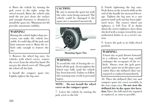
Since this tire has limited tread life the
original equipment tire should be re-
paired (or replaced) and reinstalled
on your vehicle at the first opportu-
nity.
Do not install a wheel cover or at-
tempt to mount a conventional tire on
the compact spare wheel, since the
wheel is designed specifically for the
compact spare tire. Do not install
more than one compact spare tire and
wheel on the vehicle at any given time.WARNING!
Compact spares are for temporary
emergency use only. With these
spares, do not drive more than
80 km/h. Temporary use spares
have limited tread life. When the
tread is worn to the tread wear in-
dicators, the temporary use spare
tire needs to be replaced. Be sure to
follow the warnings, which apply to
your spare. Failure to do so could
result in spare tire failure and loss
of vehicle control.FULL SIZE SPARE (for
versions/markets, where
provided)
The full size spare is for temporary
emergency use only. This tire may
look like the original equipped tire on
the front or rear axle of your vehicle,
but it is not. This spare tire may have
limited tread life. When the tread is
worn to the tread wear indicators, the
temporary use full size spare tire
needs to be replaced. Since it is not the
same as your original equipment tire,
replace (or repair) the original equip-
ment tire and reinstall on the vehicle
at the first opportunity.
LIMITED-USE SPARE (for
versions/markets, where
provided)
The limited-use spare tire is for tem-
porary emergency use only. This tire is
identified by a label located on the
limited-use spare wheel. This label
contains the driving limitations for
this spare. This tire may look like the
original equipped tire on the front or
rear axle of your vehicle, but it is not. Installation of this limited-use spare
tire affects vehicle handling. Since it is
not the same as your original equip-
ment tire, replace (or repair) the origi-
nal equipment tire and reinstall on the
vehicle at the first opportunity.
WARNING!
Limited-use spares are for emer-
gency use only. Installation of this
limited-use spare tire affects ve-
hicle handling. With this tire, do
not drive more than the speed listed
on the limit-use spare wheel. Keep
inflated to the cold tire inflation
pressure listed on your Tire and
Loading Information Placard lo-
cated on the driver’s side door
opening. Replace (or repair) the
original equipment tire at the first
opportunity and reinstall it on your
vehicle. Failure to do so could result
in loss of vehicle control.
TIRE SPINNING
When stuck in mud, sand, snow, or ice
conditions, do not spin your vehicle's
250