Page 225 of 360

operate at a fixed speed until addi-
tional speeds are selected. This allows
the front occupants to control the vol-
ume of air circulated in the vehicle
and cancel the Auto mode.
The operator can also select the direc-
tion of the airflow by selecting one of
the following positions.
Panel ModeAir is directed through the out-
lets in the instrument panel.
These outlets can be adjusted for di-
rection, and turned on or off to control
airflow.
NOTE: For maximum airflow to
the rear, the center instrument
panel outlets can be directed to-
ward the rear seat passengers.
Bi-Level Mode
Air comes from the instrument
panel outlets, floor outlets and
defrost outlets. A slight amount of air
is also directed through the side win-
dow demister outlets. NOTE: In many temperature po-
sitions, the BI-LEVEL mode is de-
signed to provide cooler air out of
the panel outlets and warmer air
from the floor outlets.
Floor Mode
Air comes from the floor out-
lets. A slight amount of air is
directed through the defrost and side
window demister outlets.
Mix Mode
Air comes from the floor, de-
frost and side window demist
outlets. This mode works best in cold
or snowy conditions. It allows you to
stay comfortable, while keeping the
windshield clear.
Defrost Mode
Air comes from the windshield
and side window demist out-
lets. Use DEFROST mode with maxi-
mum blower and temperature settings
for best windshield and side window
defrosting. NOTE: While operating in the
other modes, the system will not
automatically sense the presence
of fog, mist or ice on the wind-
shield. DEFROST mode must be
manually selected to clear the
windshield and side glass.
Air Conditioning (A/C)
The Air Conditioning (A/C) button
allows the operator to manually acti-
vate or deactivate the air conditioning
system. When in A/C mode and the
ATC is set to a cool temperature, de-
humidified air flows through the air
outlets. If Economy mode is desired,
press the A/C button to turn off the
A/C mode in the ATC display and
deactivate the A/C system.
NOTE:
If the system is in Mix, Floor or
Defrost Mode, the A/C can be
turned off, but the A/C system
shall remain active to prevent
fogging of the windows.
219
Page 226 of 360

If fog or mist appears on thewindshield or side glass, select
Defrost mode and increase
blower speed.
Recirculation Control
When outside air contains
smoke, odors, or high hu-
midity, or if rapid cooling is
desired, you may wish to
recirculate interior air by pressing the
Recirculation control button. Recir-
culation mode should only be used
temporarily. A LED will illuminate on
the Recirculation control button when
Recirculation mode is selected. Push
the button a second time to turn off
the Recirculation mode LED and al-
low outside air into the vehicle.
NOTE: In cold weather, use of the
Recirculation mode may lead to
excessive window fogging. The Re-
circulation mode is not allowed in
Defrost mode to improve window
clearing operation. Recirculation
will be disabled automatically if
this mode is selected. Rear Automatic Temperature
Control (ATC) — If Equipped
The rear ATC system has floor air
outlets at the rear of the right side
sliding door, and overhead outlets at
each outboard rear seating position.
The system provides heated air
through the floor outlets or cool, de-
humidified air through the headliner
outlets.
The rear system temperature control
is on the front ATC panel located on
the instrument panel.
Pressing the Rear Temperature Lock
button on the front ATC panel, illumi-
nates a lock symbol in the rear dis-
play. The rear temperature and air
source are controlled from the front
ATC panel.
Rear second row occupants can only
adjust the rear ATC control when the
Rear Temperature Lock button is
turned off.
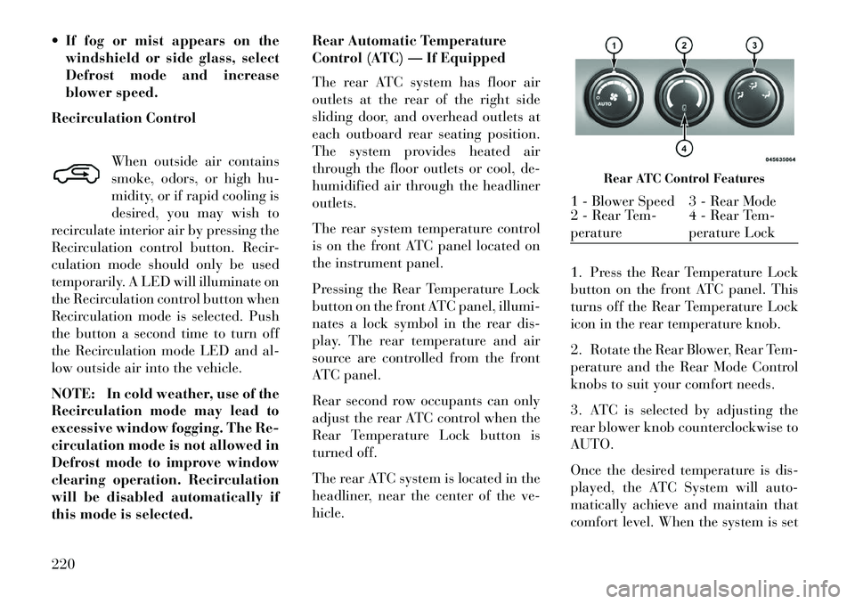
The rear ATC system is located in the
headliner, near the center of the ve-
hicle.
1. Press the Rear Temperature Lock
button on the front ATC panel. This
turns off the Rear Temperature Lock
icon in the rear temperature knob.
2. Rotate the Rear Blower, Rear Tem-
perature and the Rear Mode Control
knobs to suit your comfort needs.
3. ATC is selected by adjusting the
rear blower knob counterclockwise to
AUTO.
Once the desired temperature is dis-
played, the ATC System will auto-
matically achieve and maintain that
comfort level. When the system is set
Rear ATC Control Features
1 - Blower Speed 3 - Rear Mode
2 - Rear Tem-
perature
4 - Rear Tem-
perature Lock
220
Page 227 of 360

up for your comfort level, it is not
necessary to change the settings. You
will experience the greatest efficiency
by simply allowing the system to
function automatically.
NOTE:
It is not necessary to move thetemperature settings for cold or
hot vehicles. The system auto-
matically adjusts the tempera-
ture, mode and fan speed to pro-
vide comfort as quickly as
possible.
The temperature can be dis- played in English or Metric units
by selecting the “Display Units
of Measure in” customer-
programmable feature. Refer to
the “Electronic Vehicle Informa-
tion Center (EVIC) — Customer-
Programmable Features” in this
Section.
Rear Blower Control
The rear blower control knob can be
manually set to off, or any fixed
blower speed, by rotating the knob
from low to high. This allows the rear seat occupants to control the volume
of air circulated in the rear of the
vehicle.
CAUTION!
Interior air enters the Rear Auto-
matic Temperature Control System
through an intake grille, located in
the right side trim panel behind the
third row seats. The rear outlets are
located in the right side trim panel
of the 3rd Row seat. Do not block or
place objects directly in front of the
inlet grille or heater outlets. The
electrical system could overload
causing damage to the blower mo-
tor.
Rear Temperature Control
To change the temperature in the rear
of the vehicle, rotate the temperature
knob counterclockwise to lower the
temperature, and clockwise to in-
crease the temperature. The rear tem-
perature settings are displayed in the
front ATC panel.
When rear controls are locked by the
front system, the Rear Temperature
Lock symbol on the temperature knob is illuminated and any rear over-
head adjustments are ignored.
Rear Mode Control
Auto Mode
The rear system automatically main-
tains the correct mode and comfort
level desired by the rear seat occu-
pants.
Headliner Mode
Air comes from the outlets in
the headliner. Each of these
outlets can be individually adjusted to
direct the flow of air. Moving the air
vanes of the outlets to one side will
shut off the airflow.
Bi-Level Mode
Air comes from both the head-
liner outlets and the floor out-
lets.
NOTE: In many temperature po-
sitions, the Bi-Level mode is de-
signed to provide cooler air out of
the headliner outlets and warmer
air from the floor outlets.
221
Page 228 of 360

Floor ModeAir comes from the floor out-
lets.
SUMMER OPERATION
The engine cooling system in air con-
ditioned vehicles must be protected
with a high-quality antifreeze coolant
to provide proper corrosion protection
and to protect against engine over-
heating. A solution of 50% ethylene
glycol antifreeze coolant and 50%
water is recommended. Refer to
“Maintenance Procedures” in “Main-
taining Your Vehicle” for proper cool-
ant selection.
WINTER OPERATION
To ensure the best possible heater and
defroster performance, make sure the
engine cooling system is functioning
properly and the proper amount,
type, and concentration of coolant is
used. Refer to “Maintenance Proce-
dures” in “Maintaining Your Vehicle”
for proper coolant selection. Use of
the air Recirculation mode during
Winter months is not recommended,
because it may cause window fogging. VACATION/STORAGE
Before you store your vehicle, or keep
it out of service (i.e., vacation) for two
weeks or more, run the air condition-
ing system at idle for about five min-
utes, in fresh air with the blower set-
ting on high. This will ensure
adequate system lubrication to mini-
mize the possibility of compressor
damage when the system is started
again.
WINDOW FOGGING
Vehicle windows tend to fog on the
inside in mild, rainy and/or humid
weather. To clear the windows, select
Defrost or Mix mode and increase the
front blower speed. Do not use the
Recirculation mode without A/C for
long periods, as fogging may occur.
OUTSIDE AIR INTAKE
Make sure the air intake, located di-
rectly in front of the windshield, is
free of obstructions such as leaves.
Leaves collected in the air intake may
reduce airflow, and if they enter the
plenum they could plug the water
drains. In Winter months make sure
the air intake is clear of ice, slush and
snow.
OPERATING TIPS
A/C AIR FILTER
On vehicles equipped with Automatic
Temperature Control (ATC), the cli-
mate control system filters out dust
and pollen from the air. Refer to “Air
Conditioning” in “Maintaining Your
Vehicle” for filter replacement
instructions.222
Page 229 of 360

5
STARTING AND OPERATING
STARTING PROCEDURES . . . . . . . . . . . . . . . . . .227 AUTOMATIC TRANSMISSION . . . . . . . . . . . . .227
KEYLESS ENTER-N-GO (for versions/markets,where provided) . . . . . . . . . . . . . . . . . . . . . . .228
NORMAL STARTING — GASOLINE ENGINE . .228
EXTREME COLD WEATHER (BELOW 29°C) . . . . . . . . . . . . . . . . . . . . . . . .229
IF ENGINE FAILS TO START . . . . . . . . . . . . . .229
AFTER STARTING . . . . . . . . . . . . . . . . . . . . . .230
NORMAL STARTING – DIESEL ENGINE . . . . .230
AUTOMATIC TRANSMISSION . . . . . . . . . . . . . . .232
KEY IGNITION PARK INTERLOCK . . . . . . . . .232
BRAKE/TRANSMISSION SHIFT INTERLOCKSYSTEM . . . . . . . . . . . . . . . . . . . . . . . . . . . . .233
SIX-SPEED AUTOMATIC TRANSMISSION . . .233
GEAR RANGES . . . . . . . . . . . . . . . . . . . . . . . .234
DRIVING ON SLIPPERY SURFACES . . . . . . . . . .238
ACCELERATION. . . . . . . . . . . . . . . . . . . . . . . .238
TRACTION . . . . . . . . . . . . . . . . . . . . . . . . . . . .238
DRIVING THROUGH WATER . . . . . . . . . . . . . . .238
FLOWING/RISING WATER. . . . . . . . . . . . . . . .239
SHALLOW STANDING WATER. . . . . . . . . . . . .239
223
Page 230 of 360

POWER STEERING . . . . . . . . . . . . . . . . . . . . . . .240 POWER STEERING FLUID CHECK . . . . . . . . .240
PARKING BRAKE . . . . . . . . . . . . . . . . . . . . . . . .241
ANTI-LOCK BRAKE SYSTEM (ABS) . . . . . . . . . . .242
ANTI-LOCK BRAKE WARNING LIGHT . . . . . .243
ELECTRONIC BRAKE CONTROL SYSTEM (FOR VERSIONS/MARKETS, WHERE PROVIDED) . . .243
TRACTION CONTROL SYSTEM (TCS) (FOR VERSIONS/MARKETS, WHERE
PROVIDED) . . . . . . . . . . . . . . . . . . . . . . . . . .244
BRAKE ASSIST SYSTEM (BAS) (FOR VERSIONS/MARKETS,
WHERE PROVIDED) . . . . . . . . . . . . . . . . . . . .244
ELECTRONIC STABILITY CONTROL (ESC) . .245
TIRES — GENERAL INFORMATION . . . . . . . . . .247
TIRE PRESSURE . . . . . . . . . . . . . . . . . . . . . . .247
TIRE INFLATION PRESSURES . . . . . . . . . . . .248
TIRE PRESSURES FOR HIGH-SPEEDOPERATION . . . . . . . . . . . . . . . . . . . . . . . . . .248
RADIAL-PLY TIRES . . . . . . . . . . . . . . . . . . . . .249
SPARE TIRE MATCHING ORIGINAL EQUIPPED TIRE AND WHEEL
(for versions/markets, where provided) . . . . . .249
COMPACT SPARE TIRE (for versions/markets, where provided) . . . . . .249
FULL SIZE SPARE (for versions/markets, where provided) . . . . . .250
224
Page 231 of 360

LIMITED-USE SPARE(for versions/markets, where provided) . . . . . .250
TIRE SPINNING . . . . . . . . . . . . . . . . . . . . . . .250
TREAD WEAR INDICATORS . . . . . . . . . . . . . .251
LIFE OF TIRE . . . . . . . . . . . . . . . . . . . . . . . . .251
REPLACEMENT TIRES . . . . . . . . . . . . . . . . . .251
TIRE SAFETY INFORMATION . . . . . . . . . . . . . . .253
Tire Markings . . . . . . . . . . . . . . . . . . . . . . . . .253
Tire Identification Number (TIN) . . . . . . . . . . .256
Tire Terminology And Definitions. . . . . . . . . . .257
Tire Loading And Tire Pressure . . . . . . . . . . . .258
TIRE ROTATION RECOMMENDATIONS . . . . . . .261
TIRE PRESSURE MONITOR SYSTEM (TPMS) . .261
BASE SYSTEM . . . . . . . . . . . . . . . . . . . . . . . . .263
PREMIUM SYSTEM(for versions/markets, where provided) . . . . . .264
TPMS DEACTIVATION AND REACTIVATION . .267
FUEL REQUIREMENTS — GASOLINE ENGINE . . . . . . . . . . . . . . . . . . . . . . .267
METHANOL . . . . . . . . . . . . . . . . . . . . . . . . . .268
ETHANOL . . . . . . . . . . . . . . . . . . . . . . . . . . . .268
CLEAN AIR GASOLINE . . . . . . . . . . . . . . . . . .268
MMT IN GASOLINE . . . . . . . . . . . . . . . . . . . . .268
MATERIALS ADDED TO FUEL . . . . . . . . . . . .269
FUEL REQUIREMENTS — DIESEL ENGINE . . . .269
225
Page 232 of 360
ADDING FUEL . . . . . . . . . . . . . . . . . . . . . . . . . .270 LOCKING FUEL FILLER CAP (GAS CAP)(for versions/markets, where provided) . . . . . .270
TRAILER TOWING . . . . . . . . . . . . . . . . . . . . . . .271
COMMON TOWING DEFINITIONS . . . . . . . . . .271
BREAKAWAY CABLE ATTACHMENT . . . . . . . .272
TOWING TIPS . . . . . . . . . . . . . . . . . . . . . . . . .277
RECREATIONAL TOWING (BEHIND MOTORHOME, ETC.) . . . . . . . . . . . . . .279
TOWING THIS VEHICLE BEHIND ANOTHER VEHICLE . . . . . . . . . . . . . . . . . . . . . . . . . . . . .279
226