Page 209 of 659

REAR SUSPENSION
AND
DRIVE LINE
4-19
BRAKE BRAKE
DISC SHOE
OUTER
BEARII
-. -,
-«#*;>•
BRAKE
CAMPER
/
/ /
/ /
si—a
wC—
SPINDLE
^ SUPPOR1
BEARING
^ SPACER
INNER
" BEARING
DRIVE
" FLANGE
BEARING
-PRELOAD
SPACER
DEFLECTOR
CONTROL
ARM
Fig.
46-Wheel Spindle
and
Support Cross-Section (Corvette)
assembly is installed.
d. Pack outer bearing with a high-melting point
wheel bearing lubricant and position on spindle.
Large end of bearing should be toward shoulder
on spindle.
e. Press bearing on spindle using a bearing spacer
and Tool J-9436 as installers, as shown in Fig-
ure 50.
5. Pack spindle inner bearing with a high-melting point
-wheel bearing lubricant and position bearing in
spindle support - small end of bearing should be
positioned inward.
PRESS RAM
BEARING CUP
Fig.
48—Installing Spindle Bearing Cup (Corvette)
Fig.
49—Unseating Drive Spindle Outer Bearing (Corvette)
Fig.
47—Bearing Cup Removal (Corvette)
Fig.
50—Removing and Installing Drive Spindle
Outer Bearing (Corvette)
CHEVROLET CHASSIS SERVICE MANUAL
Page 210 of 659

REAR SUSPENSION AND DRIVE LINE 4-20
Fig.
51—Shock Absorber Installation (Corvette)
6. Tap new spindle inner grease seal into seal bore
and install deflector over support inner end.
Installation
1.
Position support over torque arm bolts with strut
rod fork toward center of vehicle and downward.
Place backing plate over studs and torque nuts to
specifications.
2.
Connect parking brake cable to actuating lever.
3.
Install drive spindle assembly as outlined previously
in this section under "Wheel Bearing Adjustment".
4.
If new spindle support or associated parts are in-
stalled, determine correct shim size as follows.
a. Assemble spindle to support, using a .145" shim.
b.
Check bearing adjustment and correct as neces-
sary, following adjustment procedures previously
outlined.
DIFFERENTIAL CARRIER SUPPORT
BRACKET REPLACEMENT
1.
Place a 1/2" thick block of wood or steel between
nose of differential carrier and floor pan. This will
prevent carrier from twisting upward when support
bracket is disconnected.
2.
Remove carrier support-to-crossmember attaching
bolt.
3.
Remove nut from both of the bracket-to-carrier
through bolts.
4.
Slide bolts to one side until bolt head contacts floor
well. Mark the floor well at this point and drill a
3/4"
diameter hole for each bolt in floor well and
remove bolts.
5. Assemble carrier support bracket by reversing
above procedure. Torque all affected parts to
specifications.
6. Insert plastic plugs from the inside of the floor well
holes to prevent dust and water entry.
STRUT ROD SHAFT STRUT ROD
CAMBER CAM
AND BOLT
Fig.
52—Strut Rods (Corvette)
SHOCK ABSORBER (Fig. 51)
Removal
1.
Disconnect shock absorber upper mounting bolt*
2.
Remove lower mounting nut and lock washer.
3.
Slide shock upper eye out of frame bracket and pull
lower eye and rubber grommets off strut rod mount-
ing shaft.
4.
Inspect grommets and shock absorber upper eye for
excessive wear.
Installation
1.
Slide upper mounting eye into frame mounting
bracket and install bolt, lock washer and nut.
2.
Place rubber grommet, shock lower eye, inboard
grommet, washers and nut over strut rod shaft.
3.
Torque nuts to specifications.
STRUT ROD AND BRACKET (Fig. 52)
Removal
1.
Raise vehicle enough to provide working clearance.
2.
Disconnect shock absorber lower eye from strut
rod shaft.
3.
Remove strut rod shaft cotter pin and nut. With-
draw shaft by pulling toward front of vehicle (fig. 53).
4.
Mark relative position of camber adjusting cam and
Fig.
53-Removing Strut Rod Shaft (Corvette)
CHEVROLET CHASSIS SERVICE MANUAL
Page 211 of 659

REAR SUSPENSION AND DRIVE LINE 4-21
Fig.
54—Marking Camber Cam and Bracket (Corvette)
bracket, so they may be reassembled in same loca-
tion (fig. 54).
5.
Loosen camber bolt and nut. Remove four bolts se-
curing strut rod bracket to carrier and lower
bracket.
6. Remove cam bolt nut and cam and bolt assembly.
Pull strut down out of bracket and remove bushing
caps.
7.
Inspect strut rod bushings for wear and replace
where necessary. Replace strut rod if it is bent or
damaged in any way.
Repairs
1.
With strut rod bushing centered over Tool J-7877-2
and with strut rod supported horizontally, press or
drive bushing from rod, using Tools J-7877-i and
J-7079-2 as shown in Figure 55.
2.
With strut rod end centered over Tool J-7877-2 and
rod supported horizontally, press or drive bushing
into arm using Tools J-7877-3 and J-7079-2 as
shown in Figure 55. Tool J-7877-3 should bottom
on strut rod when bushing is fully installed.
Installation
1.
Place bushing caps over inboard bushing and slide
rod into bracket. Install cam and bolt assembly and
adjust cam to line up with mark on bracket. Tighten
nut but do not torque at this point.
SPRING
LINK BOLT
SPRING
CUSHION
SPRING
CUSHION
CENTER
CLAMP
PLATE
J-7877-3
J-7877-1
STRUT ROD 11 s* ^#3 STRUT ROD
BUSHING
Fig.
56—Spring Mounting (Corvette)
2.
Raise bracket and assemble to carrier lower mount-
ing surface. Torque bolts to specifications.
3.
Raise outboard end of strut rod into spindle support
fork and insert strut rod shaft into fork so that flat
on shaft lines up with corresponding flat in spindle
fork. Install retaining nut, but do not torque.
4.
Place shock absorber lower eye and bushing over
strut shaft, install washer and nut and torque to
specifications.
5.
Lower vehicle to floor and torque camber cam nut
and strut rod shaft nut to specifications. Then in-
stall cotter pin through rod bolt.
6. Check rear wheel camber and adjust where
necessary.
SPRING (Fig. 56)
Removal
1.
Raise rear of vehicle and support on frame slightly
forward of torque control arm pivot points. Remove
wheels and tires.
Fig.
55—Strut Rod Bushing Replacement
Fig.
57—Chain Installation (Corvette)
CHEVROLET CHASSIS SERVICE MANUAL
Page 212 of 659

REAR SUSPENSION AND DRIVE LINE 4-22
Fig.
58—Removing Clamp Plate (Corvette)
2.
Place floor jack under spring at link bolt, and raise
spring until nearly flat.
3.
Wrap 1/4", or 5/16" chain with grab hook around
suspension crossmember and spring and hook chain
securely with grab hook. Secure chain to spring with
C ela rnp to prevent slipping (fig. 57).
CAUTION: Use 1/4" or 5/16" chain only with
a sate grab hoo^for this operation. Do not use
rope,
wiro, cable .or other method of retaining
spring.
4.
Lower jack to free link bolt and remove link bolt
cotter pin, nut and rubber cushions.
Fig.
60—Removing Center Boit (Corvette)
5.
Support and raise spring end as in Step 2 above,
remove chain when loose.
6. Carefully lower jack until spring tension is com-
pletely released.
7.
Repeat Steps 2-6 on other side.
8. Remove four bolts and washers securing spring
center clamp plate (fig. 58).
9. Drop spring and slide out from under vehicle (fig.
59).
Repairs
•1.
Clamp spring center section in vise and remove
. center bolt (fig. 60).
2.
Release vise, remove spring and separate leaves.
3.
Replace worn or damaged liners as necessary and
replace any broken leaves.
4.
Replace main leaf spring cushion retainers by
chiseling over flared portion until retainer may be
knocked out of
leaf.
Place new retainers into posi-
tion and flare over with a ball peen hammer or other
suitable tool.
5.
Insert drift into center bolt holes in leaves to align
spring leaves (fig. 61). Install center bolt and tighten
securely.
installation
1.
Place spring on carrier cover mounting surface,
indexing center bolthead with hole in cover.
Fig.
59—Lowering Spring (Corvette)
Fig.
61—-Aligning Spring Leaves (Corvette)
CHEVROLET CHASSIS SERVICE MANUAL
Page 213 of 659

REAR SUSPENSION AND DRIVE LINE 4-23
Fig.
62—Torque Control Arm (Corvette)
2.
Place center clamp plate in position and install four
bolts and washers. Tighten bolts and torque to
specifications.
3.
Raise spring outer end with floor jack until spring
is nearly flat and secure with chain as in Step 3-
Removal.
.4.
Lower jack, align torque control arm with spring
end and insert link bolt, rubber cushions and re-
tainers. Install castellated nut on link bolt and
tighten until cotter pin hole in bolt is visible. In-
sert new cotter pin and bend ends around.
5. Raise spring end with jack under link bolt, and re-
move chain and C clamp when loose.
6. Carefully lower jack, making sure rubber cushions
remain indexed in retainers.
7. Remove jack and repeat on opposite side. Install
wheels and tires, remove frame supports and lower
vehicle to floor.
TORQUE CONTROL ARM (Fig. 62)
Removal
1.
Disconnect spring on side torque arm is to be re-
moved. Follow Steps 1-6, Spring-Removal.
NOTE:
If vehicle is so equipped, disconnect
stabilizer rod from torque arm - refer to
"Stabilizer Rod Replacement".
2.
Remove shock absorber lower eye from strut rod
shaft.
3.
Disconnect and remove strut rod shaft and swing
strut rod down.
4.
Remove four bolts securing axle drive shaft to
spindle flange and disconnect drive shaft.
NOTE:
It may be necessary to force torque
arm outboard to provide clearance to drop drive
shaft.
5. Disconnect brake line at wheel cylinder inlet or
caliper and from torque arm. Disconnect parking
brake cable.
6. Remove torque arm pivot bolt and toe-in shims and
pull torque arm out of frame. Tape shims together
and identify for correct reinstallation.
RETAINER
RETAINER
PLATE
BUSHING
CONTROL ARM
Fig.
63—Torque Control Arm Bushing Cross-Sect ion (Corvette)
NOTE:
For service operations pertaining to
the spindle support assembly, refer to service
operations under Wheel Spindle and Support
earlier in this section.
Repairs (Fig. 63)
1.
Using 11/16" drill, drill out flared end of bushing
retainer (fig. 64).
2.
Remove special retainer plate and tap retainer out
of bushing.
3.
Remove bushings by spreading them apart with a
chisel and tap out of arm (fig. 65).
NOTE:
If bushing diameters are severely
rusted in torque arm, and arm tends to spread
during removal, clamp arm in a C-clamp to
prevent spreading.
Fig.
64—Drilling Out Retainer Flare (Corvette)
CHEVROLET CHASSIS SERVICE MANUAL
Page 214 of 659

REAR SUSPENSION AND DRIVE LINE 4-24
4
i*
5
Fig.
65—Removing Bushings (Corvette)
4.
Lightly oil new bushing diameters (not rubber por-
tion) and start bushings squarely in arm.
5. Install Tool J-7055-1 as shown in Figure 66 and
press bushings into place.
6. When bushings are fully installed, place special
plate over flared portion of new bushing retainer
and insert retainer into bushing.
7. Out of 5/8" thick steel plate 1-1/2" wide make flar-
ing tool support to the dimensions shown in Figure
67 and drill clearance holes as shown for 2
—
1/2"
bolts.
8. Place fabricated back-up plate on flared end of bush-
ing retainer and assembly Tool J-8111-23 to plate
with 2-1/2" bolts 5" long. Make sure threaded hole
in J-8111-23 is centered over unflared end of bushing
retainer and that chambered retainer plate is cen-
tered over retainer tube.
9. Lightly oil pointed end of J-8880-5 screw and thread
into J-
8111-23
until pointed "end contacts bushing
retainer. Continue threading J-8111-23 until retainer
is flared (fig. 68).
Installation
1.
Place torque arm in frame opening.
2.
Place toe-in shims in original position on both sides
of torque arm, install pivot bolt and tighten but do
not torque at this point.
Fig.
67—Flaring Tool Back-Up Plate (Corvette)
3.
Raise axle drive shaft into position and install to
drive flange. Torque bolts to specifications.
4.
Raise strut rod into position and insert strut rod
shaft so that flat lines up with flat in spindle sup-
port fork. Install nut and torque to specifications.
5. Install shock absorber lower eye and tighten nut
to specifications.
6. Connect spring end as outlined under Spring-
Bistallation, Steps 3-6'.
NOTE:
If vehicle is so equipped, connect sta-
bilizer shaft to torque arm - refer to "Sta-
bilizer Shaft Replacement".
7. Install brake disc and caliper, wheel and tire and
lower vehicle. Tighten torque arm pivot bolt. Bleed
brakes as outlined in Section 5-Brakes.
SUSPENSION CROSSMEMBER
Removal
1.
Disconnect and remove spring as outlined under
Spring-Removal.
2.
Remove differential carrier assembly as outlined
under Differential Carrier-Removal in this section.
3.
Support crossmember, remove bolts securing
crossmember isolation mounts to frame and lower
crossmember (fig. 69).
Fig.
66—Installing Bushings (Corvette)
Fig.
68—Flaring Retainer (Corvette)
CHEVROLET CHASSIS SERVICE MANUAL
Page 215 of 659

REAR SUSPENSION AND DRIVE LINE 4-25
Fig.
69—Removing Crossmember (Corvette)
4.
Remove bolts securing carrier cover to cross-
member.
5.
Inspect rubber isolation mounts for aging and re-
place where necessary.
Repairs—Isolation Mount
1.
Bend back isolation mount tabs to allow mount re-
moval (fig. 70).
2.
Place crossmember on a suitable support and press
mount out of arm using a piece of suitable size pipe
or tubing on outer shell or inner insert.
3.
Place new mount into position on crossmember,
compress outer sleeve and press mount into place
until it is fully and squarely seated.
4.
After installation, bend over locking tabs.
Installation
1.
Install carrier cover to crossmember and torque
bolts to specifications.
2.
Raise crossmember into position and install mount-
ing bolts. Torque bolts to specifications.
3.
Install differential carrier assembly as outlined
under Differential Carrier
-
Installation in this
section.
4.
Install wheels and tires, remove frame supports and
lower vehicle.
STABILIZER SHAFT REPLACEMENT
1.
Raise rear of vehicle and support at frame side rail
with stand jacks.
2.
Disconnect stabilizer shaft at both torque arms (fig.
71).
Remove stabilizer shaft brackets from the
frame and withdraw assembly from vehicle.
ISOLATION MOUNT
CROSSMEMBER
BEND OVER TABS AFTER INSTALLATION
Fig.
70—Crossmember Mount Cross-Section (Corvette)
3.
Inspect bushings for signs of deterioration, and in-
spect shaft for bends, breaks or other defects - do
not attempt to straighten shaft - replace parts as
deemed necessary.
4.
Position bushings on shaft and loosely install shaft
to torque arms and at frame brackets.
5.
Align shaft to assume proper placement when bolts
are torqued, and torque attaching bolts to
specifications.
Fig.
71—Stabilizer Shaft Installation (Corvette)
CHEVROLET CHASSIS SERVICE MANUAL
Page 216 of 659

REAR SUSPENSION
AND
DRIVE LINE
4-26
DRIVE LINE
REAR AXIE
INDEX
Page
General
Description
4-26
Chevrolet,
Camaro,
Chevelle
and
Chevy
II 4-26
Corvette
4-26
Maintenance
and
Adjustments
4-27
Lubricant
4.37
Lubricant'
Leaks
4_27
Axle Bolts
and
Wheel
Nuts
4-27
Rear Axle Noise
Diagnosis
4-29
Gear Noise
4_29
Bearing
Noise
4-29
Failure
Analysis
4^9
Hypoid
Gears
4..3Q
Differential Gears. 4_30
Bearings
....'.
4.30
Component Parts Replacement
(Chevrolet, Chevelle, Camaro and Chevy n ..... 4.30
Axle Assembly ,. . 4_30
Removal 4 30
Installation * ' 4 3Q
Axle Shaft . . . 4-31
Removal 4-31
Wheel Bolt Replacement 4-31
Oil Seal and/or Bearing Replacement. 4-31
Brake Flange Plate Replacement 4-31
Installation 4-32
Pinion Flange, Dust Deflector and/or
Oil Seal Replacement 4-32
Component Parts Replacement (Corvette) 4-34
Axle Driveshaft .- 4-34
Removal 4-34
Repairs 4-34
Installation. . 4-34
Pinion Flange, Dust Deflector and/or Oil Seal. .... 4-35
Removal 4-35
Inspection . 4-35
Installation .- 4-35
Differential Carrier 4-36
Removal 4-36
Installation 4-36
Positraction Differential Unit-On the Vehicle Check . . 4-37
\
GENERAL DESCRIPTION
CHEVROLET, CHEVELLE, CHEVY
I! AND
CAMARO
The rear axle
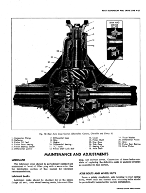
(fig. 72) is a
semifloating, fabricated
construction type consisting
of a
cast carrier with large
bosses
on
each
end
into which
two
welded steel tubes
are fitted.
The
carrier contains
an
overhung hypoid
pinion
and
ring gear.
The
differential
is a
two pinion
arrangement.
The axle housing
is
made up
of
two steel welded tubes
pressed into
the
crossbore
of the
cast carrier
-
each
tube
is
puddle welded
at
three places
to the
carrier.
Welded-on brackets provide attachment points
for
Chevelle springs,; shock absorbers,
and
lower control
arms.
Chevrolet models have welded-on brackets
for
control arms,
tie
rod, and shock absorbers. The housing
on Chevy II and Camaro has welded brackets
for
mounting
lower spring
pad
and shock absorber.
A
welded flange
is
provided
for
brake flange plate attachment.
The overhung hypoid drive pinion
is
supported
by
two
preloaded tapered roller bearings.
The
pinion shaft
is
sealed
by
means
of a
molded, spring loaded, rubber seal.
The seal
is
mounted
on the
pinion shaft flange which
is
splined and bolted
to
the hypoid pinion shaft.
The hypoid ring gear
is
bolted
to a
one-piece differen-
tial case which
is
supported
by two
preloaded tapered
roller bearings.
CORVETTE
The Corvette rear axle
is of the
type where
the dif-
ferential carrier housing enclosing
the
differential
and
hypoid gears
is
supported
on a
crossmember mounted
to
the chassis frame.
The
differential
is
connected through
universal joints
to the
drive shafts
and
wheels
(fig. 73).
The internal components
of the
carrier
are of
conven-
tional design, incorporating
a
hypoid gear
set
with
an
overhung pinion supported
on two
pre-loaded, tapered
roller bearing assemblies,
and a
two-pinion differential
assembly supported
on
tapered roller bearings. Pinion
mounting distance adjustments
are
made through the
use
of shims,
as are the
differential bearing pre-load
and
backlash adjustments.
The
differential side gears drive
two splined yokes which
are
retained laterally
by
snap
rings located on the yoke splined end. The yokes
are
sup-
ported on caged needle bearings pressed into
the
carrier,
adjacent
to the
differential bearings.
A
lip seal, pressed
in outboard
of
the bearings, prevents
oil
leakage and dirt
entry.
The
carrier cover
is
bolted
to the
carrier and
provides accessibility
to the
internal parts.
The
cover
incorporates two integral, reinforced mounting pads which
serve
as the
carrier attaching point
to the
suspension
crossmember,
and an
attaching point
for the
spring
center section. The filler plug
is
located on the right side
of the cover near the bolting flange.
All service operations allow carrier removal without
removing
the
carrier cover. Cover removal
is
not nec-
essary
in any of the
service procedures except
in
the
case
of
complete carrier housing replacement,
as the
carrier and cover
are
serviced
as
an assembly.
CHEVROLET CHASSIS SERVICE MANUAL