Page 185 of 659

FRONT SUSPENSION 3-21
Chevy II
Removal
1.
Support control arm on Tool J-7 574-4 and insert
Spacer J-9514 (fig. 34).
2,
Press bushing out with Tool J-9226 and Handle
J-7079-2 (fig. 34).
Installation
With Spacer J-9514 still in control arm, invert control
arm and press in new bushing with Tool, J-7474-2 and
Handle J-7079-2 until bushing is fully seated.
CAUTION: It should be noted that control arm
bushing diameters are unequal and bushing must
be pressed into position through larger diameter
only.
CROSS SHAFT AND/ON BUSHINGS
Corvette
Removal
1.
Remove bolt, lock washer and collar from each end
of cross shaft.
2.
Thread a 7/16 x 20 capscrew (furnished with Tool
J-5888) to the bottom of the threads in one end of the
cross shaft.
3.
Support control arm in an arbor press on Tool
J-5888-3,
as shown in Figure 35.
NOTE:
Be certain bushing flange does not
contact support.
4.
Press on cap screw until bushing is free of control
arm. Discard bushing.
5. Remove cap screw from cross shaft. Insert it in
other end of shaft. Invert control arm on support.
Again be certain bushing flange does not contact
support.
6. Press on cap screw until bushing is free of control
arm. Discard bushing.
Installation
1.
With cross shaft in control arm and Tool J-7052-1
in position, place control arm on Tool J-5888-3.
Hand start bushing into control arm and over end of
cross shaft.
NOTE:
The end of the shaft with the two bolt
holes should be toward front of control arm.
2.
Install Tool J-7052-5 over bushing. Be certain
three-piece spacer is not over-lapping bushing holes
in control arm.
3.
Press bushing into control arm until flange contacts
control arm (fig. 36).
4.
Invert arm in press and repeat the process on the
other bushing. After installation, cross shaft should
be free enough to be rotated by hand.
5. Install collar, lock washer and cap screw in each end
of cross shaft. Tighten to torque shown in Specifica-
tions after spring installation.
UPPER CONTROL ARM SPHERICAL JOINT
Chevrolet, Chevelle, Comoro and Corvette
Inspection
The upper spherical joint is checked for wear by
checking the torque required to rotate the ball stud in the
assembly. After performing the first four steps under
"Replacement" below, install a stud nut on the stud and
measure the torque required to turn the stud in the as-
sembly with a torque wrench. Specified torque for a new
joint is 9 lbs. ft. If torque readings are excessively
high or low, replace the ball joint. If excessive wear is
indicated in upper joint, both upper and lower joints
should be replaced.
NOTE:
This inspection does not necessitate
upper control arm removal.
Replacement
1.
Support the vehicle weight at the outer end of the
lower control arm.
2.
Remove the wheel and tire assembly.
3.
Remove cotter pin and nut from upper control arm
ball stud.
4.
Remove the stud from knuckle.
5. Cut off the ball joint rivets with a chisel.
6. Install new joint and retain in place with the special
nuts and bolts supplied.
7. Reassemble ball stud to the steering knuckle.
Chevy II
Inspection
The following on-the-vehicle check is to determine ball
joint wear.
NOTE:
The upper ball joint is a loose fit when
not connected to the steering knuckle. Wear may
be checked without disassembling the ball stud
by
using'
the following procedure:
1.
While vehicle weight is still on front wheels, insert
upper control arm support as shown in Figure 14.
2.
Raise vehicle and allow wheel and tire to hang free.
3.
Measure distance from tip of ball stud to top surface
of control arm.
4.
Place adjustable jackstand under tire and raise
slightly to take up ball joint looseness.
5. Repeat Step 3 and if the difference in measurements
exceeds 3/32", the joint is excessively worn and
should be replaced.
Replacement
1.
With vehicle weight still on front wheels, install
spacer between upper control arm and frame side
rail (fig. 15). Raise vehicle.
2.
Remove wheel and tire.
3.
Disconnect stabilizer link (if present) and strut rod
at lower control arm.
4.
Remove cotter pin and nut from upper ball joint stud.
5. Break ball stud loose. Drop lower control arm,
steering knuckle and brake assembly with an adjust-
able jackstand until upper control arm ball joint is
easily accessible.
6. Using a large chisel, cut off the three ball joint re-
taining plate rivet heads. It may be necessary to
drill out rivet heads before chiseling.
CHEVROLET CHASSIS SERVICE MANUAL
Page 186 of 659

FRONT SUSPENSION
3-22
CHEVROLET
s-L 1 \
TYPICAL
OF
-^-x ^K CORVETTE, CHEVELLE AND CAMARO
CHEVY n
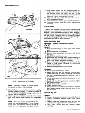
Rg.
37 - Upper Control Arm Attachment
NOTE:
Additional support to upper control
arm may be necessary while chiseling.
7. Clean ball joint seat in arm and inspect for cracking
or other evidence of fatigue. If cracks are present at
the rivet holes or ball joint opening, replace arm as
outlined later in this section.
8. Attach replacement ball joint assembly to the control
arm, using special bolts furnished with replacement
kit.
NOTE:
Use only special hardened bolts fur-
nished with this replacement kit. Do not attempt
to use other non-hardened bolts and do not at-
tempt to rivet replacement ball joint to arm.
9. Raise lower control arm and steering knuckle as-
sembly into position, insert upper ball stud into up-
per steering knuckle and install stud nut. Torque
nut as shown in the specifications and insert new
cotter pin. Install stabilizer and strut rod.
10.
Lubricate ball joint, install wheel and tire and re-
move adjustable jackstand.
11.
Lower vehicle and remove upper control arm spacer.
12.
Check and readjust caster and camber angles where
necessary.
LUBE FITTINGS
Special self threading type lube fittings are used in the
spherical joint assemblies. If it is necessary to replace
a fitting a standard threaded type may be used. However,
replacement spherical joint assemblies are supplied less
the lube fitting. Therefore it will be necessary to install
a self threading type fitting into the untapped hole pro-
vided when replacing the entire assembly.
UPPER CONTROL ARM
Chevrolet, Chevelle, Camaro and Corvette
(Fig.
37)
Removal
1.
Support vehicle weight at outer end of lower control
arm.
2.
Remove wheel and tire assembly.
3.
Remove cotter pin and nut from upper control arm
ball stud. ,
4.
REMOVE The stud from knuckle.
5. Remove two nuts retaining upper control arm shaft to
front crossmember. (Chevelle, Camaro and Cor-
vette—Note number of shims at each bolt.)
6. Remove the bolts attaching the control arm to the
frame to allow proper clearance for control arm
removal if necessary.
7. Remove upper control arm from vehicle.
Installation
1.
Install upper control arm in vehicle.
2.
Install nuts, bolts and lock washers retaining upper
control arm shaft to frame. (Chevelle, Camaro and
Corvette—Install same number of shims as removed
at each bolt.)
3.
Torque nuts as shown in the Specifications at the end
of this book.
4.
Install ball stud through knuckle, install nut, tighten
and install cotter pin.
5. Install wheel and tire assembly.
6. Lower vehicle to floor.
7. Bounce front end of vehicle to centralize bushings
and tighten bushing collar bolts as shown in the
Specifications.
Chevy II (Fig. 37)
Removal
1.
Remove spring and shock absorber as outlined above.
2.
Position adjustable jackstand under lower control
arm.
3.
Remove cotter pin and nut from upper ball joint stud
and strike steering knuckle boss to loosen stud.
4.
Drop lower control arm and steering knuckle
assembly.
CHEVROLET CHASSIS SERVICE MANUAL
Page 187 of 659

FRONT SUSPENSION 3-23
CHEVROLET
J-7052-2
CAMARO
& CHEVELLE
J-21482
CHEVROLET
J-7052-2
CAMARO
& CHEVELLE
J-21482
Fig.
38 - Removal and Installation of Upper Control Arm Bushings - Chevrolet and Chevelle (Chevelle shown as typical)
5.
Remove upper control arm pivot shaft stud nuts from
fender skirt and remove upper control arm.
6. Inspect upper control arm for cracks or bending and
replace if necessary.
Installation
1.
Insert upper control arm pivot shaft studs into rein-
forced fender skirt openings, install lock washers
and nuts and torque as indicated in the specifications.
Raise lower control arm and steering knuckle as-
sembly into position, insert upper ball joint stud into
steering knuckle and install ball stud nut and insert
new cotter pin.
Install spring and shock absorber as outlined earlier
in this section.
Lubricate ball joint and lower vehicle. Check caster
and camber angles and adjust where necessary.
UPPER CONTROL ARM
CROSS SHAFT AND/OR BUSHINGS
Chevrolet, Chevelle and Camaro
Removal
1.
Remove cap screws, lock washers and collars from
2.
3.
4.
both ends of cross shaft.
2.
Install a 3/8-24 cap screw in one end of cross shaft,
3.
Support control arm in an arbor press on Tool
J-5888-3 as shown in Figure 38.
NOTE: Be certain flange of bushing does not
contact support.
4.
Press out bushing, invert control arm and repeat
process on other bushing. Discard bushings.
5.
Remove cap screw from cross shaft.
NOTE: If bushing rubber is deteriorated to the
extent that the bushing sleeve cannot be pushed
out, release the press, install J-9502-3 as shown
in Figure 38 and press out the sleeve.
Installation
1.
Install arm in arbor press with Tool J-7052-2
(Chevrolet) or J-21482 (Chevelle and Camaro) in
place and press in one bushing using J-7052-5 as
shown while supported on Tool j-5888-3 as shown in
Figure 38.
2.
Install cross shaft in arm, invert in press, and press
in second bushing as above.
3.
Cross shaft should be able to be turned by hand.
CHEVROLET CHASSIS SERVICE MANUAL
Page 188 of 659

FRONT SUSPENSION 3-24
Fig.
39 - Removing Pivot Shaft Bushing - Chevy II
4.
Install collar, lock washer and cap screw in ends of
cross shaft. Do not tighten.
Chevy II
Removal
If a new pivot shaft is to be installed, always replace
both pivot shaft bushings.
1.
Remove nut, lock washer and metal spacer from
pivot shaft end.
2.
Stand control arm and pivot shaft assembly on
Support J-5888-3.
V
f
ff 3/a x 24
y* CAP SCREW
k
a
4f TOOL
i J-5888-3
••
Fig.
41 - Removing Upper Control Arm Cross Shaft Bushings
3.
Insert J-9513-1 over threaded end of pivot shaft.
4.
Press pivot shaft down until upper bushing diameter
is visible for approximately 5/16", then insert
J-9513-2 over journal. Release tension on pivot
shaft.
5.
Invert control arm, support on J-5888-3 and press
out bushing with J-9513-1 (fig. 39).
6. Press remaining bushing out in the same manner.
TOOL
J 7052-5
Fig.
40 - Installing Pivot Shaft Bushing - Chevy II
Fig. 42 - Installing Upper Control Arm Cross Shaft Bushing
CHEVROLET CHASSIS SERVICE MANUAL
Page 189 of 659

FRONT SUSPENSION 3-25
Installation
1.
Insert new bushing in control arm and over pivot
shaft.
2.
Support arm on J-5888-3 and insert Spacer J-
8345-1.
5.
Press bushing into place with Installer J-9513-3
(fig. 40).
Invert arm and press remaining bushing in place with
J-9513-3.
Install bushing spacers, lock washers and nuts
to pivot shaft ends. Torque as indicated in
Specifications.
NOTE:
Pivot shaft bolts must be in horizontal
position (toward center line of vehicle) before
torquing nuts.
Corvette
Removal
1.
Remove cap screws, lock washers and collars from
both ends of cross shaft.
2.
Install a 3/8-24 cap screw (furnished with Tool
J- 5888) in one end of cross shaft.
3.
Support control arm in an arbor press on Tool
J-5888-3 as shown in Figure 41.
NOTE:
Be certain flange of bushing does not
contact support.
4.
Press out bushing, invert control arm and repeat
process on other bushing. Discard bushings.
5. Remove cap screw from cross shaft.
Installation
1.
Install arm in arbor press with Tool J-7052-2 in
place and press in one bushing while supported on
Tool J-5888-3 as shown in Figure 42.
2.
Install cross shaft in arm, invert in press, and press
in second bushing as above.
3.
Cross shaft should be able to be turned by hand.
4.
Install collar, lock washer and cap screw in ends of
cross shaft. Do not tighten.
CHEVROLET CHASSIS SERVICE MANUAL
Page 190 of 659

FRONT SUSPENSION 3-26
SPECIAL TOOLS
1.
J-5888-3
2.
J-6874-5
3. J-6874-8
4. J-6874-9
5. J-7052-2
6. J-7052-5
7. J-7079-2
8. J-7574-2
9. J-7574-4
0. J-8092
Support-
Spring Compressor
Adapter for J-6874-5
Spacer
Installer
Driver Handle
Installer
Support
Driver Handle
11.
12.
12A.
13.
14.
15.
16.
17.
18.
Fig.
43-
J-8849
J-8850
J-9502-3
J-9226
J-9513-1
J-9513-2
J-9513-3
J-9514
J-9519-7
Front Suspension Special Tools
Installer
Installer
Remover
Remover
Remover
Remover
Installer
Spacer
Remover
19.
J-9519-10
20.
J-9519-16
21.
J-9519-17
22.
J-21058-8
23.
J-21058-15
24.
J-21474-2
25.
J-21474
26.
J-21474-8
28.
J-21474-13
Clamp
Installer
Receiver
Nut
Screw
Installer
Receiver
Remover
Installer
29.
J-21482
30.
J-21830-7
31.
J-21878
32.
J-21474-3
33.
J-21474-4
34.
J-21474-5
35.
J-21474-6
36.
J-22323-1
37.
J-22323-2
Spacer
Receiver Bridge
Spacer
(Not Illustrated)
(Not Illustrated)
(Not Illustrated)
(Not illustrated)
(Not Illustrated)
(Not Illustrated)
CHEVROLET CHASSIS SERVICE MANUAL
Page 191 of 659

SECTION
4
REAR SUSPENSION
AND
DRIVE LINE
CONTENTS
OF
THIS SECTION
Page
Rear Suspension
4-1
Drive Line.
. 4-26
Rear Axle ......
4-26
Propeller Shaft
and
Universal Joints
Special Tools
4-37
4-43
REAR SUSPENSION
INDEX
General Description
4-1
Chevrolet
4-1
Chevelle
4-1
Chevy
n and
Camaro
. . . . . 4-2
Corvette
. . . . . . 4-3
Maintenance
and
Adjustments ...............
4-4
Riding Height Check (Chevrolet, Camaro,
Chevelle
and
Chevy
II) 4-5
Wheel Alignment (Corvette)
4-5
Wheel Bearing Adjustment (Corvette)
4-6
Component Parts Replacement (Chevrolet, Camaro,
Chevelle
and
Chevy
JJ) 4-7
Coil Spring
4-7
Chevrolet
4-7
Removal
4-7
Installation
4-7
Chevelle
4-8
Removal
4-8
4-8
Installation
.
Leaf Spring, Spring Seat Pads, Spring
Eye
Bushings
4-9
Chevy
H 4-9
Removal
4-9
Installation
4-9
Camaro
4-10
Removal
4-10
Installation
4-11
Shock Absorber
4-11
Chevrolet
and
Chevelle
. 4-11
Removal
4-11
Installation
. . 4-12
Chevy
II 4-12
Removal
4-12
Installation
4-rl2
Camaro
4-12
Removal
. 4-12
Installation
4-12
Control
Arm . . 4-12
Chevrolet Upper
4-12
Removal
. 4-12
Page
Bushing Replacement
. 4-13
Installation
4-14
Chevrolet Lower
4-14
Removal
4-14
Bushing Replacement
4-14
Installation
. 4-15
Chevelle Upper
and
Lower.
. 4-15
Removal
4-15
Bushing Replacement
4-15
Installation
4-17
Rear Suspension
Tie Rod
(Chevrolet)
. . .
......
. . . 4-17
Removal
4-17
Bushing Replacement
4-17
Installation
4-17
Component Parts Replacement (Corvette)
. . 4-17
Wheel Spindle
and
Support
4-17
Removal
4-17
Repairs
', . 4-17
Installation
4-18
Differential Carrier Support Bracket Replacement.
. 4-20
Shock Absorber
4-20
Removal
4-20
Installation
* .... 4-20
Strut
Rod and
Bracket
4-20
Removal
4-20
Repairs
4-21
Installation
4-21
Spring
4-21
Removal
4-21
Repairs
4-22
Installation
4-22
Torque Control
Arm 4-23
Removal
4-23
Repairs
. 4-23
Installation
4-24
Suspension Crossmember
4-24
Removal
4-24
Repairs—Isolation Mount
4-25
Installation
4-25
Stabilizer Shaft Replacement
4-25
GENERAL DESCRIPTION
CHEVROLET
The link type rear suspension (fig. 1) has two lower
control arms which maintain proper axle to frame re-
lationship and also take the acceleration, drive and
braking forces. A single upper control arm on light-
duty models (or two upper control arms on heavy-duty
models and all station wagons) limits axle rotation when
drive, acceleration or braking forces are applied. Lateral
movement of the axle is restricted by the axle-to-frame
tie rod. Two full coil springs and two direct, double
acting shock absorbers are provided for additional ride
control.
CHEVELLE
The rear suspension (fig. 2) is of the four-link design
utilizing axle mounted, full coil springs and direct,
double-acting shock absorbers.
Two rubber-bushed lower control arms, stretching
slightly outboard from axle-mounted brackets to frame
side member mounted brackets, maintain fore and aft
CHEVROLET CHASSIS SERVICE MANUAL
Page 192 of 659

REAR SUSPENSION AND DRIVE LINE 4-2
SHOCK ABSORBER
UPPER ATTACHMENT
COIL SPRING
\
R.H. UPPER
CONTROL ARM
LH.
UPPER
CONTROL ARM
(HEAVY DUTY AND
STATION WAGON)
TIE ROD
ATTACHMENT
SHOCK ABSORBER
LOWER ATTACHMENT
LOWER
CONTROL ARM
Fig.
1—Chevrolet Rear Suspension Components
relationship of the axle assembly to the vehicle proper.
These lower control arm axle brackets also mount the
axle rebound bumpers and provide for lower attachment
of the shock absorber. Upper attachment of the shock
absorber is a platform mount to the rear of the coil
spring frame bracket. The coil springs are pigtailed
at both ends; the upper end is isolated from the frame
seat by a rubber insulator, while the lower end seats
on the axle mounted spring bracket which has a vertical
flange to retain the spring.
Sideways movement of the axle assembly is controlled
by two angularly mounted, rubber-bushed upper control
arms.
Projecting ears, cast as part of the differential
carrier, provide for rear attachment and frame cross-
member mounted brackets retain them at the forward
end.
CHEVY 11 AND CAMARO
The.Chevy n and Camaro rear suspension (fig. 3 and
fig.
4) consists of two uniformly stressed rear springs
and two shock absorbers mounted to the spring lower
seats.
The
.
springs are rubber mounted at both axle
and frame attaching points, thus insuring uniform spring
loading, minimizing transmittal of road vibration to
passenger compartment, and providing a pivot point to
•MMMi
MMM—Hi—1—1——1——1MMMMiM_
[•?{aw-i
'
"'
i
\ SHOCK^^BBB^^B(^^CO1L
ABSORBER ^HH^ SPRING
g^8^"
_ LOWER
feSfcto^
CONTROL
ARM
Fig.
2—Chevelle Rear Suspension Components
CHEVROLET CHASSIS SERVICE MANUAL