Page 217 of 659

REAR SUSPENSION AND DRIVE LINE 4-27
SHIM AND
SERVICE
12
14
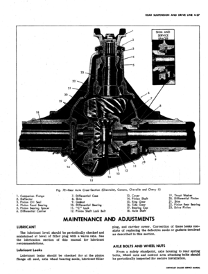
Fig.
72—Rear Axle Cross-Section (Chevrolet, Camaro, Chevelle and Chevy II)
1.
Companion Flange
2.
Deflector
3. Pinion Oil Seal
4.
Pinion Front Bearing
5. Pinion Bearing Spacer
6. Differential Carrier
LUBRICANT
7. Differential Case
8. Shim
9. Gasket
10.
Differential Bearing
11.
"Clock
12. Pinion Shaft Lock Bolt
13.
Cover
14.
Pinion Shaft
15.
Ring Gear
16.
Side Gear
17.
Bearing Cap
18.
Axle Shaft
19.
Thrust Washer
20.
Differential Pinion
21.
Shim
22.
Pinion Rear Bearing
23.
Drive Pinion
MAINTENANCE AND ADJUSTMENTS
The lubricant level should be periodically checked and
maintained at level of filler plug with a warm axle. See
the lubrication section of this manual for lubricant
recommendations.
Lubricant Leaks
Lubricant leaks should be checked for at the pinion
flange oil seal, axle wheel bearing seals, lubricant-filler
plug, and carrier cover. Correction of these leaks con-
sists of replacing the defective seals or gaskets involved
as described in this section.
AXLE BOLTS AND WHEEL NUTS
From a safety standpoint, axle housing to rear spring
bolts,
wheel nuts and control arm attaching bolts should
be periodically inspected for secure installation.
CHEVROLET CHASSIS SERVICE MANUAL
Page 218 of 659
REAR SUSPENSION
AND
DRIVE LINE
4-28
SHIM AND
SERVICE
SPACER
13
Fig.
73—Rear Axle Cross-Section (Corvette)
1.
Companion Flange
2.
Pinion Seal
3. Front Pinion Bearing
4. Rear Pinion Bearing
5. Pinion Shim
6. Pinion
7. Differential Pinion
8. Differential Side Gear
9. Differential Bearing
10.
Differential Bearing Shim
11.
Yoke Bearing
12.
Yoke Bearing Seal
13.
Side Gear Yoke
14.
Carrier Cover
15.
Differential Case
16.
Differential Pinion Shaft
17.
Thrust Washer
18.
Ring Gear
19.
Pinion Bearing Spacer
CHEVROLET CHASSIS SERVICE MANUAL
Page 219 of 659

REAR SUSPENSION AND DRIVE LINE 4-29
REAR AXLE NOISE DIAGNOSIS
Mechanical failures of the rear axle are relatively
simple to locate and correct. Noise in a rear axle is a
little more difficult to diagnose and repair. One of the
most essential parts of rear axle service is proper
diagnosis.
Ail rear axles are noisy to a certain degree. The
action of transmitting the high engine torque through a
90° turn reducing propeller shaft speed produces noise
in rear axles. This point establishes the need for a line
between normal and abnormal or unacceptable axle
noises.
Slight axle noise heard only at a certain speed or under
remote conditions must be considered normal. Axle noise
tends to "peak" at varying speeds and the noise is in no
way indicative of trouble in the axle.
If noise is present in an objectionable form, loud or at
all speeds, an effort should be made to isolate the noise
as being in one particular unit of the vehicle. Axle noise
is often confused with other noises such as tire noise,
transmission noise, propeller shaft vibration and uni-
versal joint noise. Isolation of the noise as in any one
unit requires skill and experience. An attempt to elimini-
ate a slight noise may baffle even the best of diagnos-
ticians. Such practices as raising tire pressure to
eliminate tire noise, listening for the noise at varying
speeds and on drive, float and coast, and under proper
highway conditions, turning the steering wheel from left
to right to detect wheel bearing noise, will aid even the
beginner in detecting alleged axle noises. Axle noises
fall into two categories: gear noise and bearing noise.
GEAR NOISE
Abnormal gear noise can be recognized since it pro-
duces a cycling pitch and will be very pronounced in the
speed range at which it occurs, appearing under either
"drive," "float" or "coast" conditions. Gear noise
tends to peak in a narrow speed range or ranges, while
bearing noise will tend to remain constant in pitch. Ab-
normal gear noise is rare and usually originates from
the scoring of the ring gear and pinion teeth as a result
of insufficient or improper lubrication in new assemblies.
Side gears seldom give trouble as they are used only
when the rear wheels travel at different speeds.
BEARING NOISE
Defective bearings will always produce a whine that is
constant in pitch and varies with vehicle speed. This fact
will allow you to distinguish between bearing noise and
gear noise.
1.
Pinion bearing noise resulting from a bearing failure
can be identified by a constant rough sound. Pinion
bearings are rotating at a higher speed than differen-
tial side bearings or axle shaft bearings. This
particular noise can be picked up best by testing the
car on a smooth road (black top). However, care
should be taken not to confuse tire noise with bear-
ing or gear noise. If any doubt exists, tire treads
should be examined for irregularities that would
produce such noise.
2.
Wheel bearing noise may be confused with rear axle
noise. To differentiate between wheel bearings and
rear axle, drive the vehicle on a smooth road at
medium-low speed. With traffic permitting, turn
Fig.
74—Scored Hypoid Ring Gear
the vehicle sharply right and left. If noise is caused
by wheel bearings, it will increase in the turns be-
cause of the side loading. If noise cannot be isolated
to front or rear wheel bearings, inspection will be
necessary.
3.
Side bearings will produce a constant rough noise of
a slower nature than pinion bearings. Side bearing
noise will not fluctuate in the above wheel bearing
test.
Failure Analysis
The most common types of rear axle failures are
hypoid gear tooth scoring and fracture, differential gear
fracture. and/or differential bearing failure, and axle
shaft bearing failure.
Fig.
75-Cracked Hypoid Ring Gear
CHEVROLET CHASSIS SERVICE MANUAL
Page 220 of 659

REAR SUSPENSION AND DRIVE LINE 4-30
Fig.
76—Differential Gear Failure
Hypoid Gears
Hypoid gear tooth scoring (fig. 74) is caused generally
by improper break-in, incorrect lube, insufficient gear
backlash or improper 'ring/pinion gear alignment. The
scoring will progressively lead to complete erosion of
the gear tooth, or gear tooth pitting and eventual fracture
with possible attendant damage to bearings, if the initial
scoring condition is not diagnosed in time and corrected.
Hypoid gear scoring is easily recognized by its char-
acteristic loud whine in either drive, coast or under both
conditions. Another cause of hypoid tooth fracture (fig.
75) is extended overloading of the gear set which will
produce fatigue fracture, or shock loading which will
result in sudden failure.
Differential Gears
Common causes of differential gear failure are shock
loading, extended overloading leading to fatigue failure,
and overheating of gear thrust surfaces resulting from
excessive wheel spin and consequent lubrication break-
down. Overheating will lead to seizing of thrust surfaces
or tooth failure (fig. 76).
Bearings
• Failure of axle tapered roller bearings is due pri-
marily to excessive wear caused by long service or
foreign materials in the oil. The second most common
cause of bearing failure is too tight or too loose pre-
load adjustment leading to spalling and eventual failure.
This failure may also lead to hypoid gear scoring due to
the resultant misalignment of the hypoid gear set.
COMPONENT PARTS REPLACEMENT
(Chevrolet, Cheveile, Chevy II and Camaro)
AXLE ASSEMBLY
Removal
1.
Raise vehicle to a height that will permit axle as-
sembly to hang freely and position supports under
both frame side rails.
2.
Disconnect wheel cylinder inlet lines. Disconnect and
remove brake hose and brake line retaining bracket
by removing retaining bolt from carrier cover.
3.
Loosen parking brake equalizer adjusting nut and
disconnect both rear cables at frame bracket and at
control arms. See Section 5 for detail of parking
brake cable removal.
4.
Remove two trunnion bearing "U" bolts from the
rear yoke and separate rear universal joint. Wire
propeller shaft to frame side rail and tape trunnion
bearing cups.
5. Support arid secure axle assembly with an adjustable
lifting device. On Chevrolet and Cheveile models,
loosen upper and lower control arm attaching bolts
at axle housing. (On Chevrolet models, disconnect
tie rod at axle bracket.)
6. Disconnect shock absorbers at axle brackets. Refer
to Shock Absorber Removal procedures outlined in
this section.
7. On Chevrolet and Cheveile models, lower axle as-
sembly until suspension reaches end of travel, then
disconnect spring retainers and withdraw springs
from vehicle.
8. On Chevy II and Camaro models, remove four nuts
securing lower spring seat to axle housing, then
remove spring front eye bolts or spring attaching
bracket and swing spring to rear so that it does not
interfere with axle.
9. On Chevrolet and Cheveile models, disconnect upper
and lower control arm attaching bolts at axle housing*
10.
Lower axle assembly and remove from under vehicle.
Installation
1.
Place axle assembly under vehicle and raise into
position.
2.
On Chevrolet and Cheveile models, install, but do not
tighten, upper and lower control arm attaching bolts
at axle housing.
3.
On Chevrolet models, position coil springs in upper
seats so that end of spring is indexed in seat.
4.
On Chevrolet models, install lower end of spring on
axle bracket or control arm and secure by installing
retainer and bolt. Install lock washer and retainer
nut.
5. On Cheveile pry lower pigtail of spring over vertical
flange of the axle bracket spring seat.
6. On Chevy II and Camaro models, install spring seat
pads and swing springs up into spring seats on axle
housing, making sure upper seat pads are aligned in
axle housing bracket.
7. Install spring front eye bolt and tighten, then install
spring seat lower mounting bracket and retaining
nuts.
8. Raise axle assembly to allow shock absorber and tie
rod installation. Position shock absorber in axle
bracket. Torque nut as outlined in Shock Absorber
Installation procedures.
9. Install brake hose and brake line retaining bracket
to carrier and connect wheel cylinder inlet lines.
Connect parking brake cable to frame bracket and
at control arm. Adjust parking brake and bleed
brakes as outlined in Section 5.
10.
Reassemble rear universal joint to companion flange.
11.
Support vehicle at axle and remove supports from
beneath the frame side rails.
12.
Remove supports and lower vehicle to floor. Torque
all affected parts to specifications.
CHEVROLET CHASSIS SERVICE MANUAL
Page 221 of 659

REAR SUSPENSION AND DRIVE LINE 4-31
Fig.
77—Differential Pinion Shaft Removal
AXLE SHAFT
Removal
1.
Raise vehicle to desired working height and remove
wheel and tire assembly and brake drum.
2.
Clean all dirt from area of carrier cover. *
3.
Drain lubricant from carrier by removing cover.
4.
Remove the differential pinion shaft lock screw and
the differential pinion shaft (fig. 77).
5. Push flanged end of axle shaft toward center of
vehicle and remove "C" lock from button end of
shaft.
6. Remove axle shaft from housing, being careful not
to damage oil seal.
Wheel Bolt Replacement .
Press bolts out of axle shaft flange (as illustrated in
Figure 78) and press new bolts into place, making sure
that they are tight and square with flange.
Off Seal and/or Bearing Replacement
•1.
Remove the oil seal by using the button end of the
axle shaft - insert the button end of the shaft behind
the steel case of the oil seal, then pry seal out of
bore being careful not to damage housing.
2.
Insert Tool J-8119 into bore and position it behind
bearing so that tangs on tool engage bearing outer
x race. Remove bearing, using slide hammer as shown
in Figure 79. Figure 80 shows a detail of axle
housing outer end.
3.
Lubricate new bearing with wheel bearing lubricant,
and install bearing so that it bottoms against
Fig.
79—Wheel Bearing Removal
shoulder (fig. 81). To install bearing use Tool
J-21491 for the Chevelle, Camaro and Chevy JI
light-duty axle and Tool J-21051 for all Chevrolet
models and also for Chevelle, Camaro and Chevy tl
models with heavy-duty axle.
Pack cavity between the seal lips with a high melting
point wheel bearing lubricant; position seal on tool
(Use J-21491 for the Chevelle, Camaro and Chevy II
light-duty axle and J-21051 for all Chevrolet models
and also for Chevelle, Camaro and Chevy II models
with heavy-duty axle) and position seal in axle
housing bore, tap seal into place so that it bottoms
against bearing (fig. 81).
Brake Flange Plate Replacement
1.
Remove "brake line at wheel cylinder inlet and dis-
assemble brake components from flange plate. Refer
to Section 5 for brake disassembly procedure.
2.
Remove 4 nuts securing flange plate to axle housing.
3.
Install new flange plate to axle housing and torque
nuts to specifications.
Fig.
78—Wheel Bolt Replacement
Fig.
80-Axle Housing Detail
CHEVROLET CHASSIS SERVICE MANUAL
Page 222 of 659

REAR SUSPENSION AND DRIVE LINE 4-32
HP?
Fig.
81
—Whed Bearing and/or Oil Seal Installation
4.
Install brake components on flange and connect
hydraulic line to wheel cylinder inlet. See Section 5
for brake assembly procedure.
5. Install axle shaft, brake drum and wheel and tire
assembly.
6. Bleed and. adjust brakes as outlined in Section 5.
Installation
1.
Slide axle shaft into place.
CAUTION: Exercise care that splines on end
of shaft do not damage oil seal and that they
engage with splines of differential side gear/
2.
Install axle shaft "C" lock on button end of axle-
shaft and push shaft outward so that shaft lock seats
in counterbore of differential side gear.
3.
Position differential pinion shaft through case and
pinions, aligning hole in shaft with lock screw hole.
Install lock screw and torque to specifications.
4.
Using a new gasket, install carrier cover and torque
bolts to specifications.
CAUTION: Make sure both gasket surfaces on
carrier and cover are clean before installing
new gasket. Torque carrier cover bolts in a
crosswise pattern to ensure uniform draw on
cover gasket.
5. Fill axle with lubricant to a level even with bottom
of filler hole. See Section 0 for proper lubricant.
6. Install brake drum and wheel and tire assembly.
7. Lower vehicle and test operation of axle.
PINION FLANGE, DUST DEFLECTOR
AND/OR OIL SEAL
Replacement
1.
Raise rear of vehicle and place stand jacks under
frame side rails so that axle hangs freely to allow
sufficient working room.
2.
Check wheels for freedom of rotation.
3.
Separate rear universal joint, tape trunnion bearings
to joint, position propeller shaft to one side and tie
it to frame side rail.
4.
Using Tool J-5853 with Adapter J-5810 and a suitable
socket on the pinion flange nut, rotate the pinion
through several complete revolutions and record the
torque required to keep the pinion turning (fig. 82).
If flange is to be reused, mark pinion and flange for
reassembly in the same relative position.
5. Install Tool J-8614-1 on pinion flange and remove
pinion flange nut and washer (fig. 83). (Position
Fig. 82—Measuring Drive Pinion Bearing Preload
J-8614-1 on flange so that the four notches are
toward flange.) Discard nut and use a new one
upon reassembly.
6. Thread pilot end of Tool J-8614-3 into small O.D.
end of J-8614-2. Then with J-8614-1 installed as
in Step 4, insert J-8614-2 into J-8614-1 and turn
it 45 degrees to locked position. Remove flange by
turning J-8614-3 while holding J-8614-1 (fig. 84).
7. Pry old seal out of bore, using a screw driver or a
hammer and chisel.
8. Inspect pinion flange for smooth oil seal surface,
worn drive splines, damaged ears, and for smooth-
ness of bearing contact surface. Replace if
necessary.
9. If deflector requires replacement, remove by tapping
from flange, clean up stake points; install new de-
flector, and stake deflector at three new equally
spaced positions.
NOTE:
Staking operation must be performed
in such a manner that the seal operating surface
is not damaged.
1.0. Pack the cavity between the seal lips of the pinion
flange oil seal with a lithium-base extreme pressure
lubricant, position seal in bore, then using Tools
J-21468 and J-9458, for light-duty axle and Tool
Fig. 83-—Drive Pinion Nut Removal
CHEVROLET CHASSIS SERVICE MANUAL
Page 223 of 659

REAR SUSPENSION AND DRIVE LINE 4-33
Fig.
84—Drive Pinion Flange Removal
J-21057 for heavy-duty axle, press seal into bore
until it seats against shoulder (figs. 85 and 86).
CAUTION: Pinion oil seal flange must not bot-
tom against "carrier. Press seal into carrier
bore until it seats against internal shoulder -
do not apply unnecessary pressure after seal is
seated. To do so will destroy rubber seat ancl
distort seal. ;
11.
Position and align pinion flange on pinion shaft using
Tools J-9458 and
J-8614-1.
Tool J-9458-1 is
threaded onto pinion shaft and nut tightened against
J-9458-2 to pull flange on shaft (fig. 87). Remove
Fig.
86—Drive Pinion Flange Oil Seal
Installation (Heavy-Duty)
J-9458 after flange is seated.
NOTE: The position of the pinion and flange
was previously marked so that reinstallation
may be made with flange and pinion in same
relative position.
CAUTION: Do not attempt to hammer flange
onto pinion shaft. To do so will damage ring
gear and pinion.
12.
13.
14.
15.
Pack the cavity between end of pinion splines and
pinion flange with a non-hardening sealer (such as
Permatex Type A) prior to installing washer and
nut on pinion.
Install washer and a new self-locking nut on pinion
shaft. Tighten nut to remove end play and continue
alternately tightening in small increments and check-
ing preload with torque wrench until it is the same
as that recorded in Step 4.
Reassemble the rear universal joint, and torque
"V" bolt nuts to specifications.
Lower vehicle to floor and road test for leaks.
Fig.
85—Drive Pinion Flange Oil Seal
Installation (Light-Duty)
Fig.
87—Drive Pinion Flange Installation
CHEVROLET CHASSIS SERVICE MANUAL
Page 224 of 659

REAR SUSPENSION AND DRIVE LINE 4-34
COMPONENT PARTS REPLACEMENT (CORVETTE)
AXLE DRIVESHAFT-FIGURE 88
Removal
1.
Disconnect inboard driveshaft trunnion from side
gear yoke.
2.
Bend bolt lock tabs down and remove four bolts
securing shaft flange to spindle drive flange.
3.
Pry driveshaft out of outboard drive flange pilot
and remove by withdrawing outboard end first (fig.
89).
Repairs
1.
Remove bearing lock ring from trunnion yoke.
2.
Support turnnion yoke on a piece of 1-1/4" pipe on
arbor press bed.
3.
Using suitable socket or rod, press trunnion down
far enough to drive opposite bearing cup from yoke.
4.
Remove trunnion and press other bearing cup from
yoke, being careful not to
drop'
cup
or lose bearing
rollers.
5. Remove trunnion and yoke from other joint in a
similar manner.
3
AXLE
II 1
i
c
DRI\
c
y
'E SHAFT ^
AXLE
v
DRIVE^
SHAFT
•
Fig.
88—Axle Driveshaft
6. Remove dust seals from trunnion, clean and inspect
bearing rollers and trunnion. Relubricate bearings
with a high-melting point wheel bearing type
lubricant.
NOTE:
In addition to packing the bearings,
make sure that the lubricant reservoir at the
end of each trunnion is completely filled with
lubricant. In filling these reservoirs, pack lu-
bricant into the hole so as to fill from the .
bottom. This will prevent air pockets and en-
sure an adequate supply of lubricant.
7. Place new dust seals on trunnion, cavity of seal
toward end of trunnion - then position Tool J-21556
over end of trunnion and into cavity portion of seal.
Press seal onto trunnion until tool bottoms against
trunnion (fig. 90).
NOTE:
Installation of seal is critical to proper
sealing - use specified tool during installation
to prevent seal distortion and to assure proper
seating of seal on trunnion.
8. Partially install one bearing cup into yoke. Place
trunnion in yoke and into bearing cup. Install other
bearing cup and press both bearing cups into yoke,
being careful to keep trunnion aligned in bearing
cups.
9. Press bearing cups far enough to install lock rings,
and install lock rings.
NOTE:
It may be more convenient, if neces-
sary, to use a bench vise for removal and
installation, instead of an arbor press. In this
case, proceed with disassembly and assembly
procedure as with an arbor press.
Installation
1.
Place driveshaft inboard trunnion into side gear
yokes and assemble
"XJ"
bolts. Rotate yokes so that
trunnion seats are phased 90° apart.
2.
Install outboard drive flange into spindle drive flange
pilot, position bolt lock over bolt holes and install
four bolts. Torque bolts to specification and bend
lock tabs flat against bolt heads.
Fig. 89—Removing Driveshaft
Fig.
90—
"U"
Joint Trunnion Seal Installation
CHEVROLET CHASSIS SERVICE MANUAL