2006 LAND ROVER FRELANDER 2 charging
[x] Cancel search: chargingPage 1762 of 3229
Publi s hed: 11-May-2011
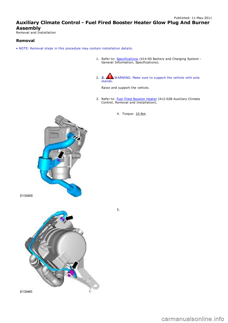
Auxiliary Climate Control - Fuel Fired Booster Heater Glow Plug And Burner
Assembly
Removal and Inst all ati on
Removal
• NOTE: Removal s t eps in t his procedure may cont ain i nst all ati on det ail s.
Refer t o: Specificati ons (414-00 Bat tery and Charging Sys tem -
General Informat ion, Specificati ons).
1.
2. W ARNING: Make sure t o s upport the vehicle wit h axle
s tands .
Rais e and s upport t he vehi cl e.
2.
Refer t o: Fuel Fired Boos t er Heat er (412-02B Auxil iary Cli mate
Control, Removal and Ins tall ati on).
3. T orque:
10 Nm 4.
5.
Page 1786 of 3229
Publi s hed: 11-May-2011
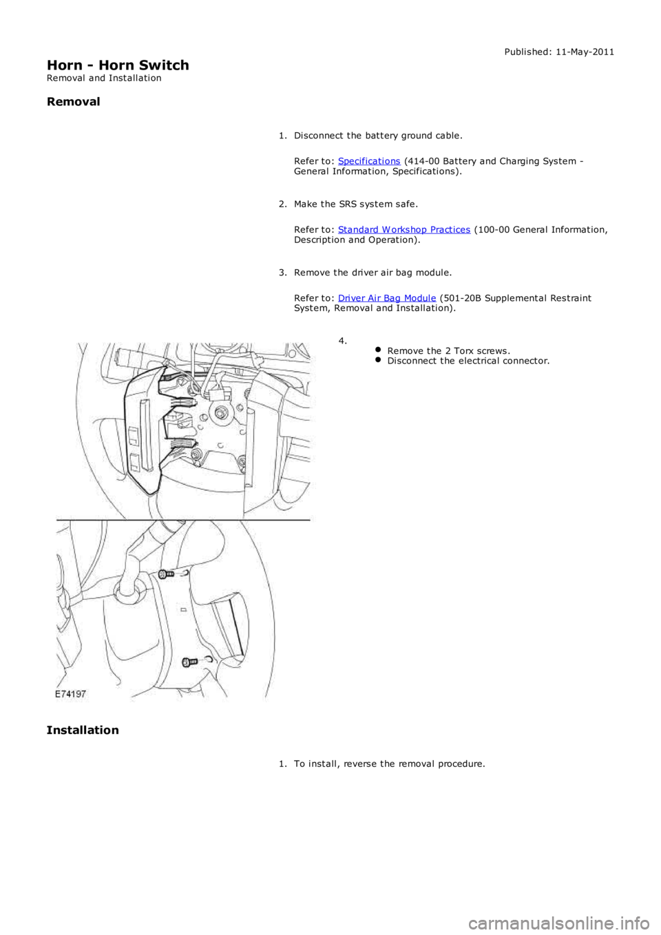
Horn - Horn Switch
Removal and Inst all ati on
Removal
Di sconnect t he bat t ery ground cable.
Refer t o: Specificati ons (414-00 Bat tery and Charging Sys tem -General Informat ion, Specificati ons).
1.
Make t he SRS s ys t em s afe.
Refer t o: Standard W orks hop Pract ices (100-00 General Informat ion,Des cript ion and Operat ion).
2.
Remove t he dri ver air bag modul e.
Refer t o: Dri ver Ai r Bag Modul e (501-20B Supplement al Res t raintSyst em, Removal and Ins tall ati on).
3.
Remove t he 2 Torx screws .Di sconnect t he electrical connect or.
4.
Installation
To i nst all , revers e t he removal procedure.1.
Page 1811 of 3229
Publi s hed: 11-May-2011
Battery and Charging System - General Information -
Vehicle Jump (Emergency) Starting - Using another vehicle
• W ARNINGS:
During normal us e, bat t eries emi t expl osi ve hydrogen gas suffi ci ent t o cause severe expl os i ons and capabl e ofcaus ing serious injury - keep s parks and naked li ght s away from the engine compart ment.
DO NOT at tempt t o s tart the di s abl ed vehi cl e i f it is sus pect ed t hat t he elect rolyte in the bat tery is frozen.
Suit able eye prot ect ion must be worn when working i n t he vicinit y of t he bat t ery.
Take care when working near rot at ing parts of t he engine.
Prior to att empti ng to st art t he dis abled vehicle, ens ure t hat the parki ng brake i s appl ied or s uit abl y chock t hewheels . Ens ure that 'P' - PARK - Aut omati c Trans mis s ion or NEUTRAL - Manual Trans mi ss i on is s elect ed.
• CAUTIO NS:
Ens ure t hat al l electrical l oads are s wi tched OFF pri or to connect ing boos ter cabl es and dis connect boos t er cablespri or to us ing el ect ri cal equipment .
Ens ure t hat the bat tery of the DO NOR vehicle is of 12 volt capaci ty and that all electrical loads on t he dis abl edvehi cl e are s wit ched O FF prior t o connecti ng boost er cables .
Ens ure t hat there is no phys ical contact between t he donor and di sabl ed vehi cl es other than t he boost er cabl es .
• NOTE: Disconnect battery: If t he remote control hands et is not functi oning, it wi ll be neces s ary t o manuall y unlock thevehi cl e us ing t he key.
Carry out the following operation in the sequence given:
1. Connect one end of the Red (+) boos t er cable to t he pos it ive (+) batt ery terminal of the DISABLED vehicle.2. Connect t he other end of the Red (+) boos ter cable t o t he posi ti ve (+) batt ery t erminal of t he DONOR vehicle.
3. Connect one end of the Black (-) boos ter cabl e t o t he Ground (-) bat t ery t ermi nal of t he DONOR vehi cle.
4. Connect t he other end of the Bl ack (-) boost er cabl e t o a good eart h point e.g. unpainted metal s urface or enginemounti ng at leas t 0.5 m (20.0 i n) from t he batt ery or fuel l ines on t he DISABLED vehi cle.
5. Start the engi ne of the DO NOR vehicle and al low it t o i dl e for a few minut es .6. Start the engi ne of the DISABLED vehicle.
7. All ow engines of both vehicles t o i dle for a few mi nut es t hen swi tch off the engine of t he DONO R vehicle.
8. Dis connect t he Black (-)boos t er cable from t he eart h point of t he PREVIO USLY DISABLED vehi cl e.9. Dis connect t he Black (-)boos t er cable from t he batt ery of t he DONO R vehicle.
10. Dis connect the Red (+) boos t er cable from t he batt ery of t he DONOR vehi cl e.
11. Dis connect the Red (+) boos t er cable from t he batt ery of t he PREVIOUSLY DISABLED vehi cl e.
Vehicle Jump (Emergency) Starting - Using a Slave Battery/Starting Aid
• W ARNINGS:
During normal us e, bat t eries emi t expl osi ve hydrogen gas suffi ci ent t o cause severe expl os i ons and capabl e ofcaus ing serious injury - keep s parks and naked li ght s away from the engine compart ment.
DO NOT at tempt t o s tart the di s abl ed vehi cl e i f it is sus pect ed t hat t he elect rolyte in the bat tery is frozen.
Suit able eye prot ect ion must be worn when working i n t he vicinit y of t he bat t ery.
Take care when working near rot at ing parts of t he engine.
Prior to att empti ng to st art t he dis abled vehicle, ens ure t hat the parki ng brake i s appl ied or s uit abl y chock t hewheels . Ens ure that 'P' - PARK - Aut omati c Trans mis s ion or NEUTRAL - Manual Trans mi ss i on is s elect ed.
• CAUTIO NS:
Ens ure t hat al l electrical l oads are s wi tched OFF pri or to connect ing boos ter cabl es and dis connect boos t er cablespri or to us ing el ect ri cal equipment .
Ens ure t hat the s l ave bat tery/s tarti ng aid are of 12 volt capacit y and t hat al l elect rical l oads on the di sabl ed vehi cl eare swi tched OFF prior t o connecti ng boos t er cables .
Page 1813 of 3229
Publi shed: 14-Jul-2011
Battery and Charging System - General Information - Battery Care
Des cript ion and Operat ion
12V LEAD ACID BATTERY CARE MANUAL FOR DEALER / RETAILER USE
1. INTRODUCTION
2. GENERAL RULES FOR BATTERY CARE
3. EQU IPMENT (MINIMU M STANDARD)
4. HEALTH AND SAFETY PRECAUTIONS
5. DETERMINING BATTERY CONDITION
6. BATTERY CHARGING AND MAINTENANCE
7. CHARGING SYSTEM TEST AND DIAGNOSIS
8. VEHICLE QUIESCENT CURRENT TESTING
APPENDIX A: BATTERY TEST PROCESS
APPENDIX B: BATTERY REPORT FORM - IN SERVICE BATTERIES ONLY
1. INTRODUCTION
This publi cat ion s ets out , for t he benefit of dealers / ret ailers worl dwide, requirement s for the care and maint enance ofbatt eri es , from the vehicles hand-over to the dealer / retail er to the handover t o the cus t omer or i n t he cas e of a sparepart batt ery from i s delivery to the dealer / retail er to it s fi tment t o a cus tomer vehicle.
It appl ies t o all t ypes of 12 volt Lead Acid Bat teries us ed, whet her they are convent ional fl ooded t echnology or Abs orbedGlas s Mat (AGM) technol ogy and als o applies to bot h Pri mary and Secondary or Auxi li ary Bat teri es.
The clearl y lai d out and ill ust rat ed s ect ions guide dealers / ret ail ers t hrough each st age of the vehicl es or s pare partsreceipt , st orage, pre-del ivery and cus tomer hand-over. This publi cat ion can be us ed as a gui de to the handli ng and care ofbatt eri es in s ervi ce. It is vi tal t o appreci ate that unles s each proces s i s ri gorousl y appl ied on al l vehi cl es, t he cust omer wil lreceive a vehicl e wit h a bat tery or a s pare part bat t ery which will not provide a s at is fact ory s ervi ce life.
It is very import ant that all t est s quoted throughout this publ icat ion are adhered to. If t hey are appli ed incorrect lybatt eri es could be s crapped unneces s ari ly. Refer to the bat tery tes t ing s ect ion for detail ed informat ion.
It is equally important therefore to not e t he fol lowing key point s :
Mos t new vehi cl es leave t he factory wi th ei ther a t rans it relay i ns t alled and/or have a trans it mode programmedint o t he vehi cl e cont rol modules . The t rans it rel ay mus t be removed and t he t rans it mode di sabled (whereappl icable) us ing an approved diagnost ic sys tem, NOT MO RE T HAN 24 HOURS before t he cust omer t akes deli very.12 Volt Lead Acid Bat teries rely on i nternal chemical proces s es to create a vol tage and deli ver current. Theseprocess es and t he int ernal chemi cal s truct ure of the bat tery can be damaged i f the bat tery is allowed t o di schargeover a number of weeks / months , or is left i n a di scharged s t at e for a lengt hy ti me peri od. For t hi s reas on t hebatt ery mus t be t es ted / re-charged i f neces sary every mont h, and MUST BE re-charged after every t hree mont hperi od of st orage. Refer to the vehicle st orage manual and updat e t he vehi cl e his t ory s heet.Under no ci rcums tances should the bat tery be dis connected wit h the engi ne running becaus e under thes e condi ti onst he alt ernator can give a very high output volt age. This hi gh t rans ient vol tage wi ll damage t he electroni ccomponents in t he vehicle. Loos e or i ncompl et e bat tery connect ions may al s o caus e high transi ent volt age.On vehicles wi th conventi onal ignit ion keys , thes e mus t not be left in t he i gni ti on lock barrel when the t rans it relayhas been removed, ot herwi se qui escent current wi ll increas e and t he bat t ery wi ll discharge more rapi dl y.Two t ypes of Lead acid bat teri es are us ed; s tandard Fl ooded t ype and AGM (Absorbed Glas s Mat) or VRLA (Valveregulat ed Lead Aci d) types. AGM batt eries offer i mproved res is t ance t o cycl ing as seen i n s top st art appli cat ions .AGM Bat teries are ful ly s ealed and cannot have t he electrolyte level t opped up.
Dealers and retailers involved in the storage, handling of vehicles and spare parts batteries have a responsibility toensure that only vehicles and spare parts having a fully satisfactory battery may be processed further through thedistribution selling chain.
• NOTE: It is very important that t est proces s es quot ed t hroughout t hi s publicati on are adhered to.
If they are not adhered t o correct ly bat teries could be scrapped unneces saril y or a batt ery wit h an is s ue remains in use.Refer t o t he bat t ery t est ing s ecti on for detai led i nformat ion.
2. GENERAL RULES FOR BATTERY CARE
Frequency of Battery Cond ition Checks.
Any batt ery i n s torage whether it i s in a vehi cle or i n s pare part s i nventory mus t have it s charge s tat us checked every 30days as des cri bed in Appendix A, and mus t be recharged every 90 days as des cribed i n t he "Bat tery Charging andMaint enance" secti on of thi s manual.
Dealer Demonstration Vehicles
Page 1814 of 3229

Due t o t he high depth of di scharge a deal er demons trati on vehi cl e batt ery may experience, bat teri es t hat are fi tt ed t ovehi cl es us ed as deal er demons trati on vehi cl es mus t be connected t o a power s upply / charger capable of deli vering 50Amps or more whil st the vehicle is being demons trated and t he engine i s not running. Thi s wi ll prevent the bat tery frombeing damaged from "energy t hroughput " wear out during a demons t rat ion.
Software Reflash, SDD work or Ig nition On related Workshop Activities.
Due t o t he high elect rical current demand and high dept h of Dis charge that can occur duri ng vehi cl e s oft ware re-flas hact ivi ti es , SDD work or igni ti on on rel at ed work in the workshop, vehi cl es that are undergoi ng s uch act ivit ies MUST havet he elect rical s ys tem on t he vehi cl e s upported wi th a power supply / charger / vehicle maintai ner capabl e of deliveri ng 50Amps or more.
Jump Starting New vehicles Before They Have Been Delivered to the Customer.
It is t he dealer / ret ailers res ponsi bili ty to ens ure the bat tery is not al lowed t o go flat by fol lowi ng the i nst ruct ionsand process es defi ned in this manual .However i f ci rcums tances dictat e t hat a new vehi cl e mus t be jump s t arted due to a flat bat t ery whil s t the vehicle isin the dealer / retail ers care, t he batt ery on this vehi cl e mus t be repl aced wi th a new one prior to del ivery to thecus t omer at the dealer / retail ers l iabil it y.The vehi cl e s houl d als o undergo inves t igati on as t o why t he batt ery went flat.Do not connect the jump s t art ing cable t o t he negat ive (-) terminal of the bat tery. Al ways connect t o t herecommended eart hing point . As defined i n t he owners handbook or s ervice document ation for t hat vehi cl e.
Jump Starting or Boost Charging Vehicles in Service
Do not connect the jump s t art ing cable t o t he negat ive (-) terminal of the bat tery. Al ways connect t o t he recommendedeart hing point . As defined i n t he owners handbook or s ervice document ati on for t hat vehi cl e.
Charging AG M Batteries
AGM bat teries mus t not be charged wit h volt ages above 14.8 Vol ts . Doing so wil l damage t hem.
Testing AGM Batteries
Midt ronics 393, 394, 493 and 494 t es ters are not capabl e of tes ti ng AGM bat teries . Doing s o can give an incorrect res ult .
W hen i t is necess ary to tes t an AGM bat tery us e t he Midt ronics EXP1080 tes ter or t he GR1 Diagnost ics Charger.
3. EQUIPMENT (MINIMUM STANDARD) (pictures are for illustration only)
Tracti on Batt ery Charger (or si mil ar st and-alone charger)
Midt ronics EXP1080 Hand-Held Tes ter
Page 1818 of 3229

6. BATTERY CHARGING AND MAINTENANCE
BATTERY CHARGING
It is es s ent ial t hat a sui tably vent ilat ed defi ned area exis ts in each dealers hip / ret ailer for bat tery charging. Li kewis e, anarea s hould be al lot ted for s crap batt eries , and clearl y indicat ed as s uch. It is recommended t hat dealers / ret ail ers al wayshave full y charged batt eri es ready for us e. However t he bat t ery MUST BE tes ted and charged i f neces sary every mont h, andcharged aft er three months i rres pecti ve of any t es t.
• CAUTIO NS:
Bat teri es mus t be re-charged aft er a maximum of 3 mont hs st orage (s ee Storage His tory s heet i n t he New VehicleStorage Manual ).
It is very important t hat when chargi ng bat t eries us ing the t racti on charger or ot her s t and-alone chargers t hat thecharger i s s et for t he correct t ype of bat tery before chargi ng commences . If t he wrong swi tch i s s elected t he res ult woul dbe a bat tery that i s not charged full y and / or overheat ing can occur. Fol low the manufact urers operat ing ins truct ions .
Do not charge AGM bat t eries wit h vol tages over 14.8 volt s as t hi s wi ll damage the bat tery.
To bri ng a s ervi ceable but di scharged batt ery back t o a full y charged condit ion proceed as follows :
Check and i f neces s ary t op-up t he batt ery el ect rolyt e level.Charge t he batt ery us ing the Mi dtroni cs Diagnos t ic Charger (USA) or Tract ion Charger (all other market s) foll owingt he manufact urers operati ng ins t ructi ons .
• NOTE: W hen us ing the Mi dtroni cs Diagnost ic Charger, aut omati c mode mus t always be us ed. Aft er chargi ng and anal ysi s,t he charger may di s pl ay ‘Top-Off Charging’, pres s STOP t o end. Do not s top chargi ng unt il t he current falls to 5A or les s,otherwis e t he batt ery wi ll not be ful ly charged.
POST-CHARGE TEST METHODS
New Batteries, Batteries in Storage and In-Service Batteries
The purpos e of thi s tes t is to ens ure that t he chargi ng process has full y charged the bat tery.
• NOTE: IT IS RECOMMENDED THAT THIS TEST IS CO NDUCTED AT LEAST 24 HOURS AFTER THE CHARGE CY CLE ISCOMPLETED.
Page 1820 of 3229
If the el ect rolyt e level is l ow, top-up usi ng dis t ill ed water.
Maint enance free and Valve Regulat ed (AGM) bat teries are s eal ed and therefore cannot be topped up.
CHARGING SYSTEM TEST AND DIAGNOSIS
For al l vehi cl es , refer to the Chargi ng Syst em - Diagnos i s and Tes t ing i n s ect ion 414-00 of the W orks hop Manual.
VEHICLE QUIESCENT CURRENT TESTING
• NOTE: On vehicles fit t ed wit h a Bat tery Monit oring Sys t em (BMS), t he diagnos t ic routi ne for quies cent drai n t es t ing i nt he approved di agnos ti c s ys t em s hould be ut il ized.
• NOTE: If a cus t omer compl ains of a vehicle bat tery that dis charges cont inuousl y or when left for a prolonged period oft ime, it is recommended t hat a quies cent drai n tes t i s performed as des cribed below.
• NOTE: The batt ery drain s hould be meas ured usi ng an approved diagnos t ic s ys tem or a Digi tal Mult i-Meter (DVOM).
The vehi cl e s houl d be i n t he locked/armed st ate (for example vehi cl e alarm full y armed), al l doors , engine and luggagecompartment l ids are open and lat ched (s o as t o appear clos ed from an electrical point of view). The t es t s houl d t akeplace aft er the vehicle has ent ered s hutdown mode. The t ime taken for this to occur after t he igni ti on is s wi tched offvaries according t o model - Refer t o Quies cent Drain in s ecti on 414-00 of the W orks hop Manual .
• NOTE: W hen t he vehicle i s armed, t he effect of t he s ecurit y s ys t em Li ght Emi tt ing Diode (LED) flas hing i s to caus e apuls ati on in the meas ured current drain. In t hi s case, eit her the average current should be taken (usi ng a Di gi tal Mul ti -Meter (DVOM) wi th an averagi ng s ys t em) or the current reading t aken, ignori ng t he bri ef hi gh current peaks .
EQUIPMENT
Approved diagnos t ic s ys tem wit h current probe or Digit al Mul ti -Met er (DVOM) wit h current probe.
METHOD OF MEASUREMENT
Using an Approved Diagnostic System
1. Swit ch off all elect rical loads and ensure t hat t he i gni ti on is off.
2. Connect the current probe t o t he approved di agnos ti c s yst em.
3. Calibrate t he probe.
4. Ins t al l a clamp around the bat tery lead/junct ion box l ead.
5. Go t o t he Quies cent Current Tes t ing s ect ion.
Using a Digital Multi-Meter (DVOM)
• NOTE: Do not us e an i n-li ne DVOM to meas ure the qui escent drain on vehi cl es fi tt ed wi th an el ect roni c throt t le. Thecurrent exceeds t he maximum amount the fus e in the DVOM is capable of handling.
1. Swit ch off all elect rical loads and ensure t hat t he i gni ti on is off.
2. Connect the current probe t o t he DVOM.
3. Calibrate t he probe.
4. Ins t al l a clamp around the bat tery lead/junct ion box l ead.
5. Go t o t he fol lowing Qui escent Current Tes ti ng s ect ion.
QUIESCENT CU RRENT TESTING
1. Swit ch ignit ion t o ‘on’ or s elect ignit ion mode i n keyles s vehi cl es and s wit ch to ‘off’ (do not crank).
2. Remove key from i gni ti on s wit ch (where appl icabl e).
3. Open and lat ch all doors , hood and l uggage compart ment li d.
4. Lock t he vehi cle us ing t he remote funct ion on the remote hands et. (Single lock onl y t o avoi d volumet ri c alarm arming).
5. Remove any ot her pot enti al el ect ri cal drai ns such as acces s ori es plugged into acces sory s ockets .
6. Record the amperage readings after t he shut down period. The model specific Amperage readings for quies cent drain arereferenced in Qui escent Drain in secti on 414-00 of t he W orks hop Manual
7. Record the fi nal readi ng on the bat tery report form Appendi x B.
• NOTE: The preferred method of t est ing foll owing an exces s ive current cons umpti on fi gure i s t o use a current probearound i ndi vi dual junct ion box l eads t o t he various s us pect ed ci rcuit s t o ident ify a potent ial caus e. Thi s is in preference t ot he old met hod of removing fus es for t he fol lowing reasons :
Many modules t ake a cons i derabl e t ime to power down. Each t ime a fuse is removed and re-fi tt ed, t he quies centdrai n current may t ake an extended peri od of ti me t o ret urn to normal (t ypi cal ly up to 45 minut es ).The drai n may be caused by a module remaini ng act ive and prevent ing t he quies cent drai n from reduci ng to normallevels .The drai n may be caused by a rel ay winding that is act ivated. Pulli ng t he fus e can all ow t his t o ‘res et ’ and the drainwil l be los t and go un-di agnos ed.
Page 1822 of 3229
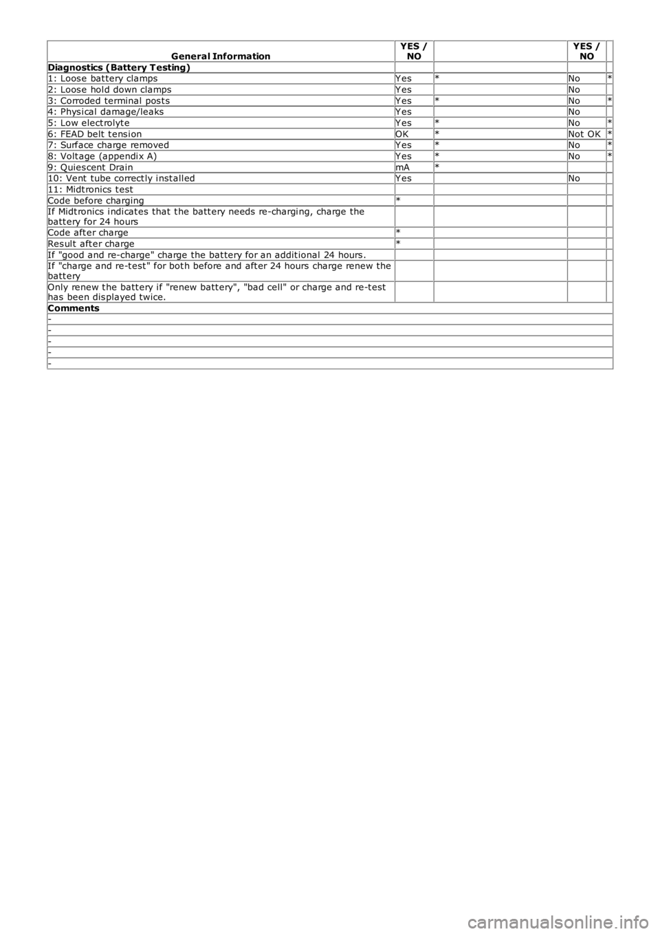
General InformationYES /NO YES /NO
Diagnostics (Battery T esting) 1: Loos e bat tery clampsY es*No*
2: Loos e hol d down clampsY es No
3: Corroded terminal pos t sY es*No*4: Phys i cal damage/leaksY es No
5: Low elect rolyt eY es*No*
6: FEAD belt t ens i onOK*Not OK*7: Surface charge removedY es*No*
8: Volt age (appendi x A)Y es*No*
9: Quies cent DrainmA* 10: Vent tube correct ly i nst all edY es No
11: Midt ronics t est
Code before charging* If Midt ronics i ndi cat es that t he batt ery needs re-chargi ng, charge thebatt ery for 24 hours
Code aft er charge*
Res ul t aft er charge*
If "good and re-charge" charge the bat tery for an addit ional 24 hours . If "charge and re-t est " for bot h before and aft er 24 hours charge renew thebatt ery
Only renew t he batt ery i f "renew batt ery", "bad cell" or charge and re-t esthas been dis played twice.
Comments-
-
--
-