Page 1619 of 3229
Publi s hed: 11-May-2011
Speed Control - I6 3.2L Petrol - Speed Control Switch
Removal and Inst all ati on
Removal
Di sconnect t he bat t ery ground cable.
Refer t o: Specificati ons (414-00 Bat tery and Charging Sys tem -General Informat ion, Specificati ons).
1.
Make t he SRS s ys t em s afe.
Refer t o: Supplement al Res t raint Sys tem (SRS) Depowering andRepowering (501-20, General Procedures ).
2.
Remove t he dri ver air bag modul e.
Refer t o: Dri ver Ai r Bag Modul e (501-20B Supplement al Res t raintSyst em, Removal and Ins tall ati on).
3.
Remove t he 2 Torx screws .Di sconnect t he electrical connect or.
4.
Installation
To i nst all , revers e t he removal procedure.1.
Page 1621 of 3229
Publi s hed: 11-May-2011
Speed Control - I6 3.2L Petrol - Speed Control Deactivator Switch
Removal and Inst all ati on
Removal
Right-hand drive vehicles
Remove t he cover and dis connect the bat tery ground cabl e.
Refer t o: Specificati ons (414-00 Bat tery and Charging Sys tem -General Informat ion, Specificati ons).
1.
Remove t he s toplamp swi tch.
Refer t o: Stoplamp Swit ch (417-01 Ext erior Light ing, Removal andInst all at ion).
2.
All vehicles
3. CAUTION: The s wit ch has a l at ching device t hatonly al lows t he s wit ch to be removed or i ns t alled whent he s wit ch plunger i s depres sed.
• NOTE: RHD ill ust rat ion shown, LHD i s s imi lar.
3.
Installation
To i nst all , revers e t he removal procedure.1.
Page 1625 of 3229
Publi s hed: 11-May-2011
Speed Control - TD4 2.2L Diesel - Speed Control Switch
Removal and Inst all ati on
Removal
Di sconnect t he bat t ery ground cable.
Refer t o: Specificati ons (414-00 Bat tery and Charging Sys tem -
General Informat ion, Specificati ons).
1.
Make t he SRS s ys t em s afe.
Refer t o: Supplement al Res t raint Sys tem (SRS) Depowering and
Repowering (501-20, General Procedures ).
2.
Remove t he dri ver air bag modul e.
Refer t o: Dri ver Ai r Bag Modul e (501-20B Supplement al Res t raint
Syst em, Removal and Ins tall ati on).
3.
Remove t he 2 Torx screws . Di sconnect t he electrical connect or.4.
Installation To i nst all , revers e t he removal procedure.
1.
Page 1627 of 3229
Publi s hed: 11-May-2011
Speed Control - TD4 2.2L Diesel - Speed Control Deactivator Switch
Removal and Inst all ati on
Removal Right-hand drive vehicles
Remove t he cover and dis connect the bat tery ground cabl e.
Refer t o: Specificati ons (414-00 Bat tery and Charging Sys tem -
General Informat ion, Specificati ons).
1.
Remove t he s toplamp swi tch.
Refer t o: Stoplamp Swit ch (417-01 Ext erior Light ing, Removal and
Inst all at ion).
2.
All vehicles 3. CAUTION: The s wit ch has a l at ching device t hat
only al lows t he s wit ch to be removed or i ns t alled when
t he s wit ch plunger i s depres sed.
• NOTE: RHD ill ust rat ion shown, LHD i s s imi lar.
3.
Installation To i nst all , revers e t he removal procedure.
1.
Page 1630 of 3229

Publi s hed: 11-May-2011
Climate Control System - General Information - Air Conditioning (A/C)
System Recovery, Evacuation and Charging
General Procedures
1. W ARNING: Servicing mus t be carried out by pers onnelfamil liar wi th bot h vehicle s ys tem and the chargi ng and tes t ingequipment. Al l operat ions mus t be carried out i n a wel l vent ilat edarea away from open flame and heat s ources .
• NOTE: The receiver dri er need onl y be changed under t he followi ngcircums t ances : There i s dirt in t he refri gerant ci rcuit ( eg.compres s or s eizure ), t he s yst em is l eaking and refrigerant has beenl os t t o at mosphere, or t he refri gerant ci rcuit has been open moret han 24 hours , due to repair.
Refrigerant recovery and recycle.
1.
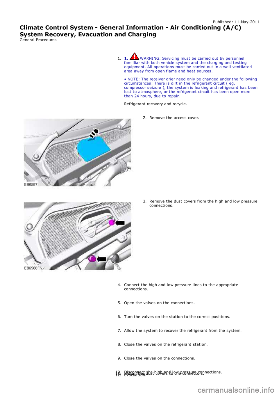
Remove t he acces s cover.2.
Remove t he dus t covers from the hi gh and low pres sureconnecti ons .3.
Connect t he high and l ow pres s ure l ines t o t he appropriat econnecti ons .4.
Open t he valves on t he connect ions .5.
Turn the valves on t he s tat ion t o t he correct pos it ions.6.
All ow t he s yst em t o recover the refrigerant from the sys tem.7.
Clos e t he valves on t he refri gerant st ati on.8.
Clos e t he valves on t he connecti ons .9.
Di sconnect t he high and l ow pres s ure connect ions.10.Inst all t he dus t covers t o t he connect ors .11.Evacuati on.12.
Page 1631 of 3229
Remove t he dus t covers from the hi gh and low pres sure connecti ons .
13.
Connect t he high and l ow pres s ure l ines t o t he appropriat e
connecti ons .
14.
Open t he valves on t he connect ions .
15.
All ow t he s tat ion t o evacuat e t he A/C sys tem.
16.
17. CAUTION: The s yst em must be evacuat ed immediatl ey
before recharging commences. Del ay bet ween evacuati on and
rechargi ng is not permit ted
Recharging
17.
Clos e t he valves on t he refri gerant st ati on.
18.
Clos e t he valves on t he connecti ons .
19.
Di sconnect t he high and l ow pres s ure connect ions.
20. Inst all t he dus t covers t o t he connect ors .
T orque: 6 Nm 21.
Inst all t he acces s cover.
22.
Page 1641 of 3229

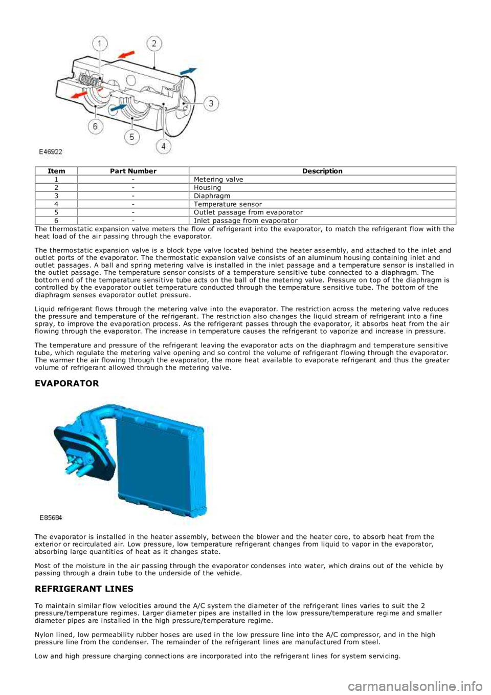
ItemPart NumberDescription
1-Met ering val ve2-Hous ing
3-Di aphragm
4-Temperat ure s ens or5-Out let pass age from evaporat or
6-Inlet pass age from evaporat or
The t hermos tat ic expans ion val ve meters the fl ow of refri gerant i nto the evaporator, to match t he refri gerant fl ow wi th t heheat load of the ai r pas s ing through t he evaporat or.
The t hermos tat ic expans ion val ve is a bl ock type valve l ocat ed behi nd the heat er as sembly, and att ached t o t he inl et andoutl et ports of t he evaporator. The t hermos t at ic expansi on valve cons i st s of an aluminum hous ing containi ng inlet andoutl et pas s ages . A ball and s pri ng met ering val ve is i nst all ed in the i nlet pass age and a t emperat ure s ensor i s ins t al led i nt he out let pas sage. The t emperature s ens or cons is t s of a t emperature s ens i ti ve tube connect ed to a diaphragm. Thebott om end of t he t emperature s ens it ive tube acts on the ball of t he met ering val ve. Pres s ure on top of t he diaphragm iscont rol led by t he evaporat or outl et t emperat ure conduct ed through the t emperat ure s ensi ti ve tube. The bott om of t hediaphragm sens es evaporat or out let pres s ure.
Liquid refrigerant flows t hrough t he metering valve i nto the evaporator. The res trict ion acros s t he metering valve reducest he pres sure and t emperature of the refrigerant . The res trict ion als o changes the l iquid st ream of refrigerant i nto a fi nes pray, to improve t he evaporati on proces s . As t he refri gerant pas s es through the evaporator, it abs orbs heat from t he airfl owing t hrough t he evaporat or. The i ncreas e i n t emperature caus es t he refri gerant to vapori ze and increas e in pres sure.
The t emperature and pres s ure of t he refri gerant l eavi ng the evaporat or act s on t he diaphragm and t emperat ure s ensi ti vet ube, which regul ate the met eri ng val ve openi ng and s o cont rol t he vol ume of refri gerant fl owing t hrough t he evaporat or.The warmer t he air flowi ng through the evaporator, the more heat avai lable to evaporat e refri gerant and thus t he greatervolume of refrigerant all owed through t he met eri ng val ve.
EVAPORATOR
The evaporat or is i nst all ed in the heater as s embly, bet ween t he blower and the heat er core, t o abs orb heat from t heexteri or or recirculat ed air. Low pres s ure, low temperat ure refrigerant changes from li qui d t o vapor i n t he evaporat or,absorbing l arge quant it ies of heat as it changes st ate.
Mos t of the moi s ture in the ai r pas s ing t hrough t he evaporat or condens es i nto wat er, whi ch drains out of the vehicl e bypass i ng through a drain tube t o t he unders ide of t he vehi cl e.
REFRIGERANT LINES
To mai nt ain si mil ar fl ow velocit ies around t he A/C s ys t em t he diamet er of t he refrigerant li nes varies t o s uit t he 2pres s ure/t emperat ure regi mes . Larger di ameter pipes are ins tal led i n t he low pres sure/t emperature regi me and s mall erdiamet er pi pes are i nst all ed in the hi gh pres sure/t emperature regi me.
Nylon l ined, low permeabi li ty rubber hos es are us ed i n t he low press ure li ne int o t he A/C compress or, and i n t he highpres s ure l ine from the condens er. The remainder of the refrigerant l ines are manufact ured from s teel.
Low and high press ure charging connecti ons are i ncorporated i nto the refrigerant li nes for s yst em s ervi ci ng.
Page 1656 of 3229
Publi s hed: 11-May-2011
Climate Control - Blower MotorLHD AWD
Removal and Inst all ati on
Special T ool(s)
412-140Remover/Ins t al ler, Bl ower Motor
Removal
1. NOTE: The recircul at ion bl end door mus t be cl os ed i n order for t heremoval of the recirculat ion bl end door housi ng.
Acti vat e reci rculati on.
1.
Di sconnect t he bat t ery ground cable.
Refer t o: Specificati ons (414-00 Bat tery and Charging Sys tem -General Informat ion, Specificati ons).
2.
Remove t he accelerat or pedal as sembl y.
Refer t o: Accelerat or Pedal (310-02 Accelerati on Cont rol , Removaland Inst all at ion).
3.
4.
Remove t he glove compartment .
Refer t o: Glove Compart ment (501-12 Ins trument Panel and
5.