2006 LAND ROVER FRELANDER 2 horn
[x] Cancel search: hornPage 10 of 3229
Publi s hed: 11-May-2011
General Information - How To Use This Manual
Des cript ion and Operat ion
Copyright Statement
Copyright.© Land Rover Ltd., 2006
All rights res erved. No part of thi s publ icati on may be reproduced, s tored in a ret ri eval s yst em or t rans mit t ed in any form,electroni c, mechanical, photocopyi ng, recordi ng or other means, wi thout pri or wri tt en permi s si on of Land Rover Ltd.,Banbury Road, Li ght horne, W arwi ck, CV35 0RG
How To Use This Manual
This manual covers al l aspects necess ary in order to s ervi ce the vehicle effect ively.
The manual i s s truct ured into fi ve main secti ons , General Informat ion, Chass is , Powert rai n, El ect ri cal and Body and Paintwit h each s ect ion deali ng wit h a specific part of a vehi cl e s ys t em.
Each of t he five mai n s ect ions contain sub-sect ions deal ing wi th it ems which form a part of t hat s pecific s ys tem.
Pages at t he s t art of the manual li s t all s ect ions avai lable. Each s ect ion has a content s li s t det ail ing, where appli cable,Speci ficat ions, Des cri pt ion and Operati on, Di agnos is and Tes ti ng, General Procedures and Repair Procedures.
W here components need t o be removed or dis ass embled in s equence, each operat ion i n the s equence wil l be identi fi ednumeri cal ly and als o graphi cal ly i n an accompanying i ll us t rat ion.
All l eft -hand and ri ght-hand references t o t he vehi cl e are taken from a posi ti on s itti ng in the driver seat l ooking forward.
All l eft -hand and ri ght-hand references t o t he engi ne are taken from a pos i ti on at the flywheel looki ng t owards t he frontcamshaft pul ley.
Ins pect ion and Verificati on
Vis ual Ins pect ion Chart s , Sympt om Charts and ot her informati on charts (s uch as diagnos t ic rout ines ) or s upplement t estprocedures wit h t echnical s pecificati ons wil l navigat e t he user t o a s peci fi c t es t procedure.
Symptom Chart
The s ymptom chart indicates s ymptoms, s ources and act ions t o addres s a condit ion.
Pinpoint Test s
For el ect ri cal s yst ems , pinpoint t es t s t eps are us ed to identi fy t he s ource of a concern in a logi cal, s t ep-by-s t ep manner.Pinpoint t es t s have two col umns: CONDITIO NS and DETAILS/RESULTS/ACTIONS.
The CONDITIONS column is us ed excl usi vel y for graphi cs and icons (wi th or wi thout capt ions ) and the DETAILS/RESULTS/ACTIONS column provi des direct ion t o another tes t s tep or s pecifi c correct ive acti ons .
The boxed numbers indicate the order in whi ch the des cribed acti on is to be carri ed out.
Component Tes ts
A component t es t is us ed when a component i s t est ed in mult ipl e pinpoint t es t s, or if a procedure i s too compl icated t o beformatt ed wi thi n a s ingle page of t he pinpoint t est .
Graphics
Test graphi cs show the meas urement or t es t t o be carried out i n a t est st ep.
A repres ent ati ve tes t er graphi c is us ed for vol tmet ers and ohmmet ers .
If mult iple measurement s are made i n a s ingle graphic, the t es t leads are drawn wi th a s ol id line unt il t he t es t l ead spl it st o indicate the mult iple measurement s , at which point dashed l ines are used.
Breakout box t ype t es t ers are repres ented by a doubl e circl e t est pi n. Tes t pins are labell ed wit h t he pin number.
• NOTE: Dimens i ons quot ed are t o des ign engineeri ng s pecificati ons wit h s ervice l imits quot ed, where appl icable.
Workshop Manual Organization
The fi ve main s ect ions, t ogether wit h t he areas whi ch they cover are given below:
Section 1 - General Informat ion.Section 2 - Chas si s.Section 3 - Powert rai n.Section 4 - Elect rical.Section 5 - Body and Paint .
Sub-s ect ion numbers appear aft er the i nit ial s ect ion number, for exampl e, Section 412-01 covers Cli mate Cont rol, whi ch ispart of t he electrical s ecti on.
In the number given above, t he first di git of the number ' 4' indicates t he s ect ion i.e. Electrical.
The s econd and t hird digit s ' 12' of t he number indicate the vehicle sys tem i.e. Climate Control.
Page 14 of 3229
Publi s hed: 11-May-2011
General Information - Standard Workshop Practices
Des cript ion and Operat ion
Vehicle in Workshop
W hen working on a vehicl e in the workshop al ways make sure t hat :
W here practi cable, t he parking brake is appli ed and t he wheel s are securely chocked to prevent t he vehi cl e movingforwards or backwards .W henever pos si ble, t he ignit ion key i s removed before any work is carried out on t he vehi cle.If the engine i s t o be run, t here i s adequat e vent il ati on, or an extract ion hos e i s us ed to remove exhaus t fumes.There i s adequat e room to rais e the vehicle and remove t he wheel s , if neces s ary.Fender covers are al ways ins tal led i f any work i s to be carri ed out in t he engine compart ment.W here practi cable, t he batt ery i s dis connected if worki ng on the engi ne, underneath t he vehicle, or if t he vehi cl e i srai sed.
• CAUTIO NS:
Prior to dis connect ing the bat tery, refer to the El ect ri cal Secti on of this manual - Bat tery dis connect ion/connect ion.For addit ional informat ion, refer t o: Specificati ons (414-01 Bat t ery, Mount ing and Cables , Speci ficat ions).
W hen el ect ri c arc wel ding on a vehi cl e, al ways dis connect t he generator wi ri ng to prevent t he pos si bili ty of a s urgeof current caus i ng damage to the i nternal component s of the generat or.
If us i ng welding equipment on t he vehicle, a s uit abl e fire exti nguis her is readily avail able.
Battery - General
• CAUTIO NS:
Prior to carrying out any procedures which i nvol ve dis connect ing/ or connecti ng the bat tery, refer t o t he ElectricalSect ion of t his manual - Batt ery di sconnect ion/connect ion.For addit ional informat ion, refer t o: Specificati ons (414-01 Bat t ery, Mount ing and Cables , Speci ficat ions).
A di s charged bat tery condit ion may have been caus ed by an electrical short ci rcuit . If t his condit ion exis t s there wil lbe an apparentl y li ve circuit on the vehicle even when al l normal circuit s are s wit ched off. This can cause arcing when t hejumper cables are connect ed.
W hi le it i s not recommended that the vehicl e is jump s t art ed, i t is recognized t hat thi s may occas ionall y be t he onl ypracti cal way t o mobi lize a vehi cl e. Prior t o at tempt ing a jump s t art , reference must be made to the El ect ri cal Secti on oft hi s manual - Jump St art ing.
Followi ng jump s tart ing of a dis abl ed vehi cle, the di s charged bat tery mus t be checked for s erviceabili ty and recharged offt he vehi cl e as s oon as poss ibl e t o avoi d permanent damage.
Do not rel y on t he generator t o res t ore a di s charged bat tery. For a generat or t o recharge a batt ery, it woul d take i n exces sof eight hours cont inuous dri vi ng wi th no addi ti onal loads placed on t he batt ery.
Always make s ure that t he jumper cabl es are adequate for the tas k.Always make s ure that t he s lave batt ery i s of the same vol tage as t he vehicle bat tery. The bat teries mus t beconnected i n paral lel.Always make s ure that s wit chabl e electric circui ts are s wi tched off before connecti ng jumper cabl es. This reducest he ri sk of arci ng occurring when the final connecti on is made.
Towing the Vehicle
W ARNING: W hen t owing i s neces sary, reference mus t be made to the Jacki ng, Lift ing and Towing Secti on of thi sManual .
W hen t he vehicle i s being t owed dock the remote cont rol and s wit ch on the ignit ion. (s t eering l ock releas ed and warni ngli ght s i ll uminated). Onl y t hen wil l the s t eering, turn s ignal lamps , horn and s t op lamps be operat ional. Fail ure t o followt hes e i nst ructi ons may res ult in pers onal injury. It mus t be noted that wit h t he engine not running, t he power s t eering andbrake boost er wil l be inoperat ive t herefore, great er effort wil l be needed t o s t eer t he vehicle and apply the brakes .
General Installation Instructions
Component removal
W henever pos si ble, clean component s and the surroundi ng area before removal .
Blank off openings expos ed by component removal .Followi ng dis connecti on, s eal fuel, oil or hydrauli c li nes i mmediat ely us ing sui table bl anki ng plugs or caps .Seal open ends of expos ed oil ways us i ng sui table tapered hardwood pl ugs or cons pi cuous pl as t ic pl ugs .Immediat el y a component i s removed, place it i n a sui table contai ner; us e a s eparate cont ai ner for each componentand it s as s ociat ed part s .
Page 75 of 3229
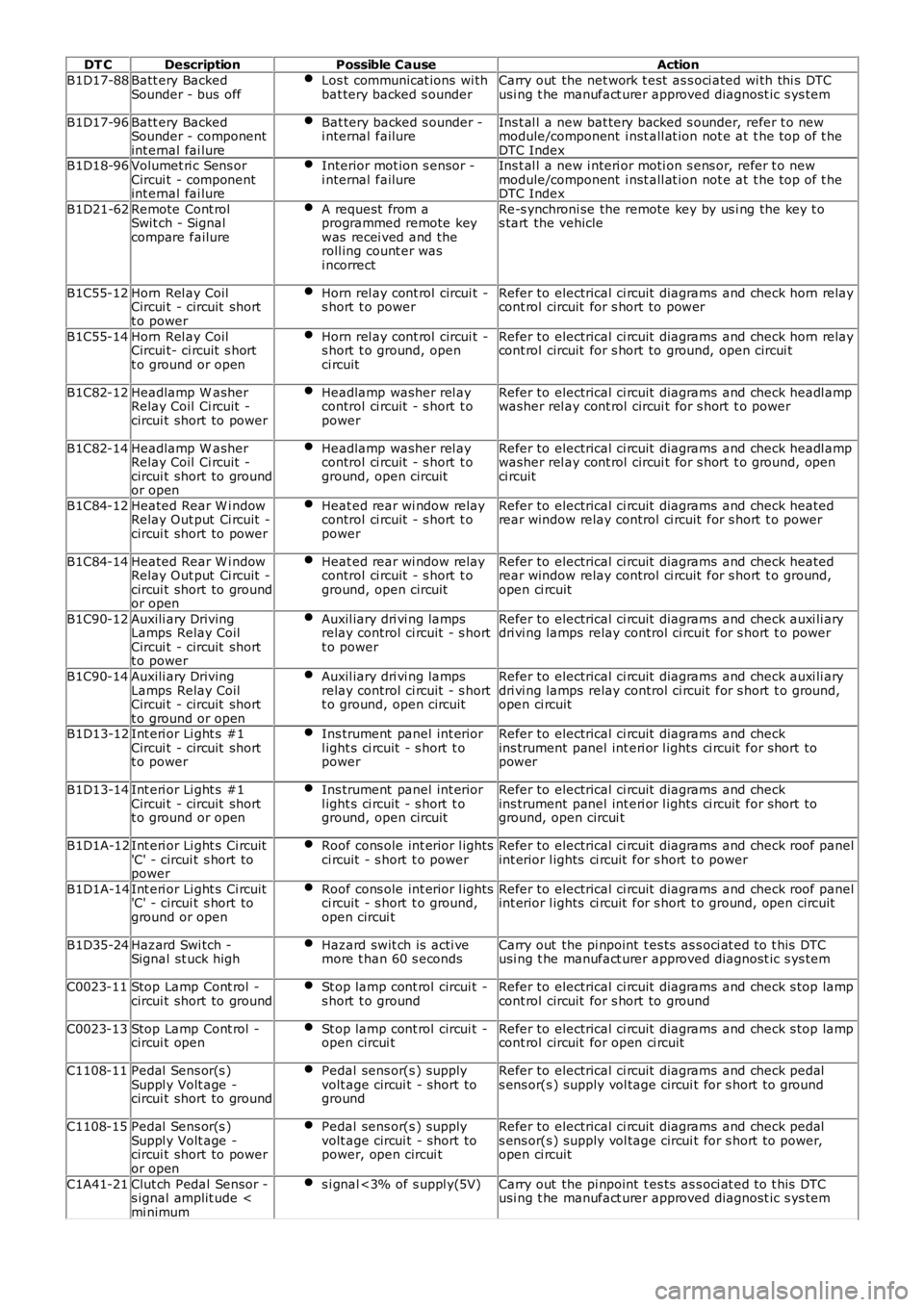
DT CDescriptionPossible CauseAction
B1D17-88Batt ery BackedSounder - bus offLos t communicat ions wi thbat tery backed s ounderCarry out the net work t est as s oci ated wi th thi s DTCusi ng t he manufact urer approved diagnost ic s ys tem
B1D17-96Batt ery BackedSounder - componentint ernal fai lure
Bat tery backed s ounder -i nternal failureIns t al l a new bat tery backed s ounder, refer t o newmodule/component i nst all at ion not e at t he top of t heDTC IndexB1D18-96Volumet ri c Sens orCircui t - componentint ernal fai lure
Interior mot ion s ensor -i nternal failureIns t al l a new i nteri or moti on s ens or, refer t o newmodule/component i nst all at ion not e at t he top of t heDTC Index
B1D21-62Remote Cont rolSwit ch - Signalcompare failure
A request from aprogrammed remote keywas recei ved and theroll ing count er wasi ncorrect
Re-s ynchroni se the remote key by us i ng the key t os tart the vehicle
B1C55-12Horn Rel ay CoilCircui t - circuit shortt o power
Horn rel ay cont rol circui t -s hort t o powerRefer to electrical ci rcuit diagrams and check horn relaycont rol circuit for s hort to power
B1C55-14Horn Rel ay CoilCircui t- ci rcuit s hortt o ground or open
Horn rel ay cont rol circui t -s hort t o ground, openci rcuit
Refer to electrical ci rcuit diagrams and check horn relaycont rol circuit for s hort to ground, open circui t
B1C82-12Headlamp W asherRelay Coil Ci rcuit -circui t short to power
Headlamp washer rel aycontrol ci rcuit - s hort t opower
Refer to electrical ci rcuit diagrams and check headl ampwasher rel ay cont rol circui t for s hort t o power
B1C82-14Headlamp W asherRelay Coil Ci rcuit -circui t short to groundor open
Headlamp washer rel aycontrol ci rcuit - s hort t oground, open circuit
Refer to electrical ci rcuit diagrams and check headl ampwasher rel ay cont rol circui t for s hort t o ground, openci rcuit
B1C84-12Heated Rear W i ndowRelay Out put Ci rcuit -circui t short to power
Heat ed rear wi ndow relaycontrol ci rcuit - s hort t opower
Refer to electrical ci rcuit diagrams and check heatedrear window relay control ci rcuit for s hort t o power
B1C84-14Heated Rear W i ndowRelay Out put Ci rcuit -circui t short to groundor open
Heat ed rear wi ndow relaycontrol ci rcuit - s hort t oground, open circuit
Refer to electrical ci rcuit diagrams and check heatedrear window relay control ci rcuit for s hort t o ground,open ci rcuit
B1C90-12Auxili ary DrivingLamps Relay CoilCircui t - circuit shortt o power
Auxil iary dri vi ng lampsrelay control ci rcuit - s hortt o power
Refer to electrical ci rcuit diagrams and check auxi li arydri vi ng lamps relay control ci rcuit for s hort t o power
B1C90-14Auxili ary DrivingLamps Relay CoilCircui t - circuit shortt o ground or open
Auxil iary dri vi ng lampsrelay control ci rcuit - s hortt o ground, open circuit
Refer to electrical ci rcuit diagrams and check auxi li arydri vi ng lamps relay control ci rcuit for s hort t o ground,open ci rcuit
B1D13-12Int eri or Li ght s #1Circui t - circuit shortt o power
Ins trument panel int eriorl ight s ci rcuit - s hort t opower
Refer to electrical ci rcuit diagrams and checkins trument panel int eri or l ights ci rcuit for short topower
B1D13-14Int eri or Li ght s #1Circui t - circuit shortt o ground or open
Ins trument panel int eriorl ight s ci rcuit - s hort t oground, open circuit
Refer to electrical ci rcuit diagrams and checkins trument panel int eri or l ights ci rcuit for short toground, open circui t
B1D1A-12Int eri or Li ght s Ci rcuit'C' - circui t s hort topower
Roof cons ole int erior l ightsci rcuit - s hort t o powerRefer to electrical ci rcuit diagrams and check roof panelint erior l ights ci rcuit for s hort t o power
B1D1A-14Int eri or Li ght s Ci rcuit'C' - circui t s hort toground or open
Roof cons ole int erior l ightsci rcuit - s hort t o ground,open circui t
Refer to electrical ci rcuit diagrams and check roof panelint erior l ights ci rcuit for s hort t o ground, open circuit
B1D35-24Hazard Swi tch -Signal st uck highHazard swit ch is acti vemore t han 60 s econdsCarry out the pi npoint t es ts as s oci at ed t o t his DTCusi ng t he manufact urer approved diagnost ic s ys tem
C0023-11Stop Lamp Cont rol -circui t short to groundSt op lamp cont rol circui t -s hort t o groundRefer to electrical ci rcuit diagrams and check s top lampcont rol circuit for s hort to ground
C0023-13Stop Lamp Cont rol -circui t openSt op lamp cont rol circui t -open circui tRefer to electrical ci rcuit diagrams and check s top lampcont rol circuit for open ci rcuit
C1108-11Pedal Sens or(s )Suppl y Volt age -circui t short to ground
Pedal sens or(s ) supplyvolt age circui t - short toground
Refer to electrical ci rcuit diagrams and check pedals ens or(s ) supply vol tage circui t for s hort t o ground
C1108-15Pedal Sens or(s )Suppl y Volt age -circui t short to poweror open
Pedal sens or(s ) supplyvolt age circui t - short topower, open circui t
Refer to electrical ci rcuit diagrams and check pedals ens or(s ) supply vol tage circui t for s hort t o power,open ci rcuit
C1A41-21Clut ch Pedal Sensor -s ignal amplit ude
Page 175 of 3229
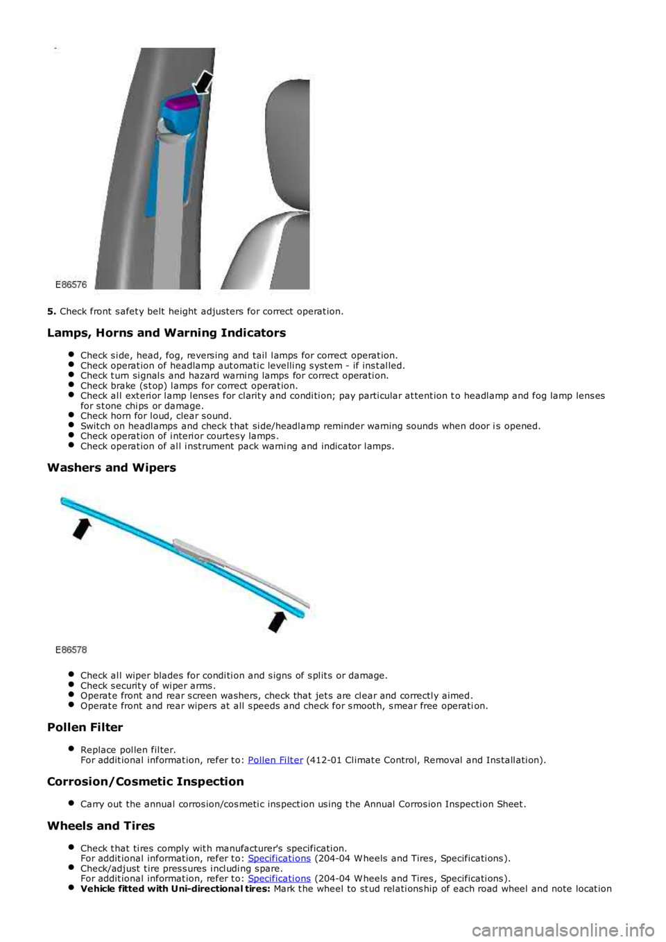
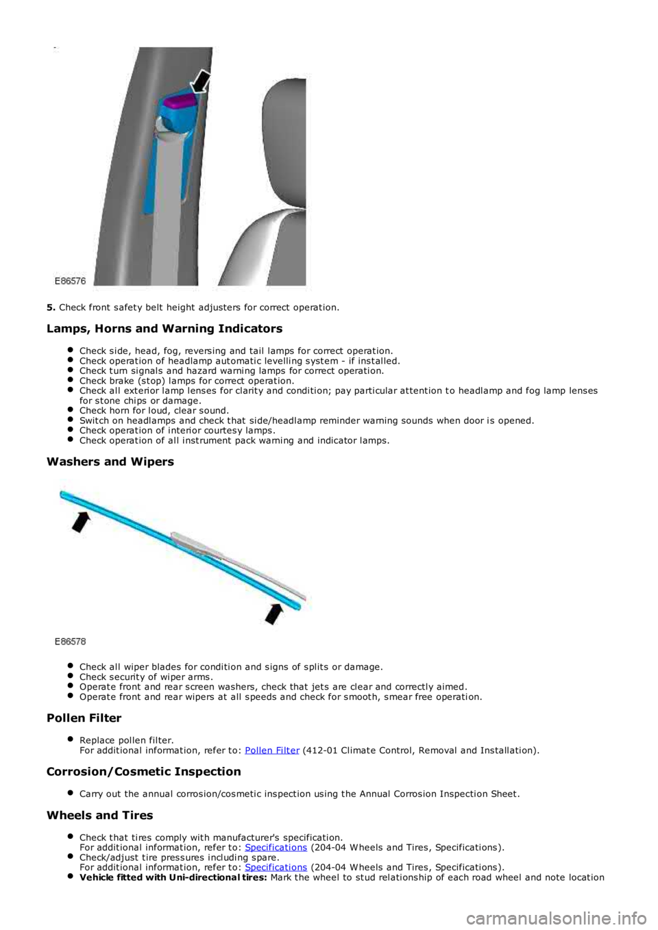
5. Check front s afet y belt height adjus ters for correct operat ion.
Lamps, Horns and Warning Indicators
Check s i de, head, fog, revers ing and tail l amps for correct operat ion.Check operat ion of headlamp aut omati c levelli ng s yst em - if ins t al led.Check t urn si gnal s and hazard warni ng lamps for correct operati on.Check brake (s t op) l amps for correct operat ion.Check al l ext eri or l amp l ens es for cl arit y and condi ti on; pay parti cular at tent ion to headl amp and fog lamp lens esfor s t one chi ps or damage.Check horn for l oud, clear s ound.Swit ch on headl amps and check t hat si de/headl amp reminder warning s ounds when door is opened.Check operat ion of i nteri or courtes y lamps .Check operat ion of al l i nst rument pack warni ng and indicator l amps.
Washers and Wipers
Check al l wiper blades for condi ti on and s igns of s pl it s or damage.Check s ecurit y of wi per arms .Operat e front and rear s creen washers, check that jet s are cl ear and correctl y aimed.Operat e front and rear wipers at all s peeds and check for s moot h, s mear free operation.
Pollen Filter
Replace pol len fil ter.For addit ional informat ion, refer t o: Pollen Fi lt er (412-01 Cl imat e Control, Removal and Ins tall ati on).
Corrosion/Cosmetic Inspection
Carry out the annual corros ion/cos meti c ins pect ion us ing t he Annual Corros ion Inspecti on Sheet .
Wheels and Tires
Check t hat ti res comply wit h manufacturer's specificati on.For addit ional informat ion, refer t o: Specificati ons (204-04 W heels and Tires , Specificati ons ).Check/adjust t ire pres s ures i ncl udi ng s pare.For addit ional informat ion, refer t o: Specificati ons (204-04 W heels and Tires , Specificati ons ).Vehicle fitted with Uni-directional tires: Mark t he wheel to st ud rel ati ons hip of each road wheel and note locat ion
Page 186 of 3229
5.
Check front s afet y belt height adjus ters for correct operat ion.
Lamps, Horns and Warning Indicators Check s i de, head, fog, revers ing and tail l amps for correct operat ion. Check operat ion of headlamp aut omati c levelli ng s yst em - if ins t al led.
Check t urn si gnal s and hazard warni ng lamps for correct operati on.
Check brake (s t op) l amps for correct operat ion.
Check al l ext eri or l amp l ens es for cl arit y and condi ti on; pay parti cular at tent ion t
o headl amp and fog lamp lens es
for s t one chi ps or damage. Check horn for l oud, clear s ound.
Swit ch on headl amps and check t hat si de/headl amp reminder warning s ounds when door i
s opened.Check operat ion of i nteri or courtes y lamps .
Check operat ion of al l i nst rument pack warni ng and indicator l amps.
Washers and Wipers
Check al l wiper blades for condi ti on and s igns of s pl it s or damage.
Check s ecurit y of wi per arms .
Operat e front and rear s creen washers, check that jet s are cl ear and correctl y aimed
.Operat e front and rear wipers at all s peeds and check for s moot h, s mear free operati
on.Pollen Filter
Replace pol len fil ter.
For addit ional informat ion, refer t o: Pollen Fi lt er (412-01 Cl imat e Control, Removal and Ins tall ati on).
Corrosion/Cosmetic Inspection
Carry out the annual corros ion/cos meti c ins pect ion us ing t he Annual Corros ion Inspec ti on Sheet .Wheels and Tires
Check t hat ti res comply wit h manufacturer's specificati on.
For addit ional informat ion, refer t o: Specificati ons (204-04 W heels and Tires , Specificati ons ).
Check/adjust t ire pres s ures i ncl udi ng s pare.
For addit ional informat ion, refer t o: Specificati ons (204-04 W heels and Tires , Specificati ons ).
Vehicle fitted with Uni-directional tires:
Mark t he wheel to st ud rel ati ons hip of each road wheel and note locat ion
Page 577 of 3229
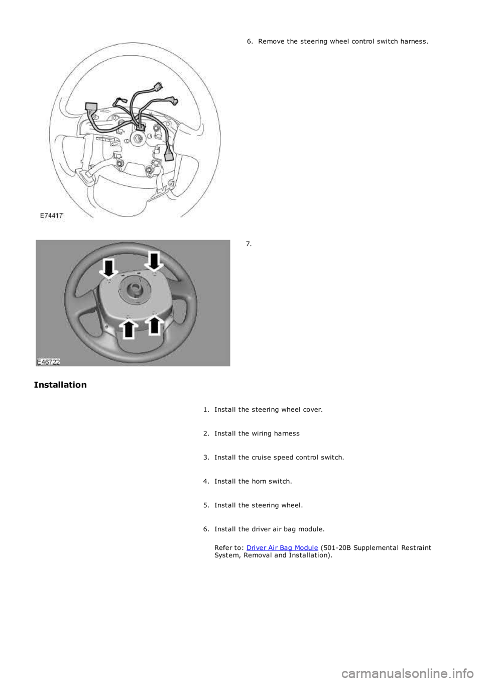
Remove t he s teeri ng wheel control swi tch harnes s .6.
7.
Installation
Inst all t he s teeri ng wheel cover.1.
Inst all t he wiring harnes s2.
Inst all t he cruis e s peed cont rol s wit ch.3.
Inst all t he horn s wi tch.4.
Inst all t he s teeri ng wheel .5.
Inst all t he dri ver air bag modul e.
Refer t o: Dri ver Ai r Bag Modul e (501-20B Supplement al Res t raintSyst em, Removal and Ins tall ati on).
6.
Page 1683 of 3229
Publi s hed: 11-May-2011
Climate Control - EvaporatorLHD AWD
Removal and Inst all ati on
Removal
• NOTE: The removal of thi s component involves cut t ing an apert ure in t he evaporator hous i ng wall and cutt ing t hrought he high and l ow pres s ure A/C l ines. A s ervice repai r ki t is s uppli ed to cover thi s procedure.
Di sconnect t he bat t ery ground cable.
Refer t o: Specificati ons (414-00 Bat tery and Charging Sys tem -General Informat ion, Specificati ons).
1.
Recover t he A/C refrigerant .
Refer t o: Air Condi ti oning (A/C) Sys tem Recovery, Evacuati on andCharging (412-00 Cl imat e Control Sys t em - General Informat ion,General Procedures).
2.
Remove t he plenum chamber panel.
Refer t o: Plenum Chamber (412-01 Cl imat e Control, Removal andInst all at ion).
3.
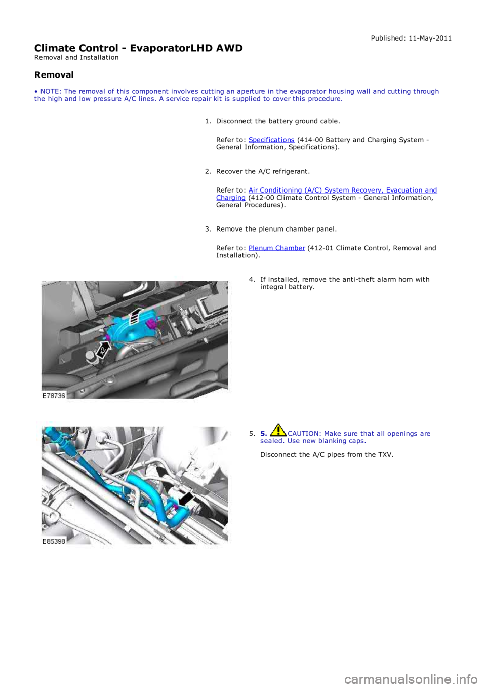
If ins tal led, remove t he anti -t heft alarm horn wit hi nt egral batt ery.4.
5. CAUTION: Make s ure that all openi ngs ares ealed. Use new blanking caps.
Di sconnect t he A/C pipes from t he TXV.
5.
Page 1690 of 3229
blanking caps.
Remove t he TXV as sembl y from t he s ervice replacement evaporator
pipes .
Guide the s ervi ce replacement evaporator pi pes t hrough t he
bulkhead s o that approximat ely 20mm is vi s ible in t he engine
compart ment.
7.
Inst all t he TXV capt ive clampi ng plat e.
8. 9.
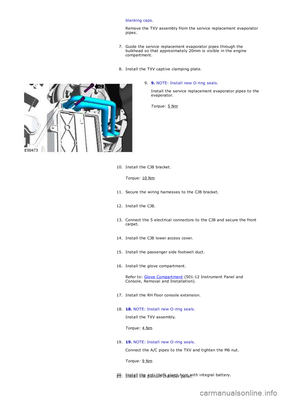
NOTE: Ins t al l new O-ri ng seal s.
Inst all t he s ervice repl acement evaporat or pipes t o the
evaporator.
T orque: 5 Nm 9.
Inst all t he CJB bracket .
T orque: 10 Nm 10.
Secure t he wiring harnes s es to the CJB bracket.
11.
Inst all t he CJB.
12.
Connect t he 5 elect rical connectors to the CJB and s ecure t he front
carpet.
13.
Inst all t he CJB lower acces s cover.
14.
Inst all t he pas s enger s ide footwel l duct .
15.
Inst all t he glove compartment .
Refer t o: Glove Compart ment (501-12 Ins trument Panel and
Consol e, Removal and Ins t al lat ion).
16.
Inst all t he RH floor cons ole ext ens ion.
17.
18. NOTE: Ins tal l new O-ring seals .
Inst all t he TXV as sembl y.
T orque: 4 Nm 18.
19. NOTE: Ins tal l new O-ring seals .
Connect t he A/C pipes t o the TXV and ti ght en t he M6 nut .
T orque: 9 Nm 19.
Inst all t he ant i-t heft alarm horn wit h i nt egral batt ery.
20.
Inst all t he plenum chamber panel.
21.