2006 LAND ROVER FRELANDER 2 clock reset
[x] Cancel search: clock resetPage 585 of 3229

Publi s hed: 11-May-2011
Steering Column Switches - Steering Column Switches
Des cript ion and Operat ion
COMPONENT LOCATION
ItemPart NumberDescription
1-Speed cont rol s wit ches2-St eering column cas e containi ng the mult ifunct ion s wit ches and cl ocks pring
3-Audio control swit ches
OVERVIEW
The winds hield wiper s wit ch is l ocat ed in the right -hand-s ide of t he cas e and retai ned wit h 2 s crews . The s wit ch isconnected t o t he mai n harness vi a a connect or at the back of the s wi tch. The s wit ch cont rols the followi ng functi ons :
W i nds hiel d wi per i nt ermit tent s low and fas t speedW i nds hiel d wi per fli ck wipeW i nds hiel d was h/wi peRear was h/wipeInt ermit tent delay s electi on.
The t urn s ignal indicator s wit ch is locat ed i n t he left -hand-si de of the cas e and ret ained wi th 2 s crews . The swi tch i sconnected t o t he mai n harness vi a a connect or on the back of t he swit ch. The s wit ch cont rol s the foll owing funct ions:
Left / right turn s ignal operati onHigh / low beam operati onHeadl amp flas hTri p comput er functi on s el ect ion (i f fit t ed).
The t rip but t on allows the driver to cycle t hough an opti on menu and als o reset t ri p cycl e mi leage cal cul ati ons . The t ripcomput er informat ion i s dis played in the i nst rument clus ter mes s age cent er (high line ins trument cl us t er onl y).
Steering wheel mount ed s wit ches on the right -hand-s ide of t he dri ver's ai rbag, cont rol the audi o and tel ephone funct ions.Swit ches on the l eft -hand-s ide of t he dri ver's ai rbag control t he s peed cont rol functi ons .
The clocks pri ng is locat ed i n the front of t he cas e and retai ned wit h four s crews . The clocks pri ng engages i n s lots in t hes teeri ng wheel bos s and t urns wi th the rotat ion of t he s teeri ng wheel. The clocks pring incorporat es a t ang which cancelst he turn s ignal indicators when the st eering wheel i s rot ated.For addit ional informat ion, refer t o: Air Bag and Safet y Belt Pretens ioner Supplement al Res traint Syst em (SRS) (501-20BSuppl ement al Rest rai nt Sys tem, Des cri pti on and Operati on).
CONTROL DIAGRAM
• NOTE: A = Hardwi red; D = Hi gh s peed CAN bus , O = LIN bus
Page 589 of 3229

1-Pres s t o s wit ch between radi o, CD, or AUX
2-Pres s t o i ncreas e volume
3-Pres s t o decrease vol ume4-Pres s and release to scrol l through preset radi o s t at ions or CD tracks . Pres s to search up or down fort he next or previous radio s t at ion/CD t rack
The audi o control s wi tches are res is ti ve ladder swi tches. Thes e s wit ches connect t o t he Infotainment Control Modul e (ICM)or Int egrated Audi o Modul e (IAM) (dependant upon the l evel of audi o fit ted t o t he vehicle) via t he clockspring.
For addit ional informat ion, refer t o: Audi o Sys tem (415-01, Des cript ion and Operat ion).
Speed Control Switches
ItemPart NumberDescription
1-Set t arget speed, or increase s peed
2-Set t arget speed, or decreas e s peed3-Res ume s et s peed
4-Cancel s s peed cont rol operati on wit hout erasi ng memorized s peed
The s peed control swit ches are res is t ive l adder type. The s ignals from the res is ti ve ladder are fed t o the st eeri ng col umnmodule (located in t he clocks pri ng) which t hen out put s t he s ignals as a local i nterconnect net work (LIN) bus s ignal to thecent ral junct ion box (CJB). The CJB trans mi ts speed cont rol s ignals on the hi gh s peed controll er area network (CAN) bus t ot he engi ne cont rol module (ECM).
For addit ional informat ion, refer t o: Speed Cont rol (310-03A Speed Cont rol - I6 3.2L Petrol, Des cript ion and Operat ion).
For addit ional informat ion, refer t o: Speed Cont rol - 2.2L Di esel (310-03, Des cri ption and Operati on).
Page 1411 of 3229
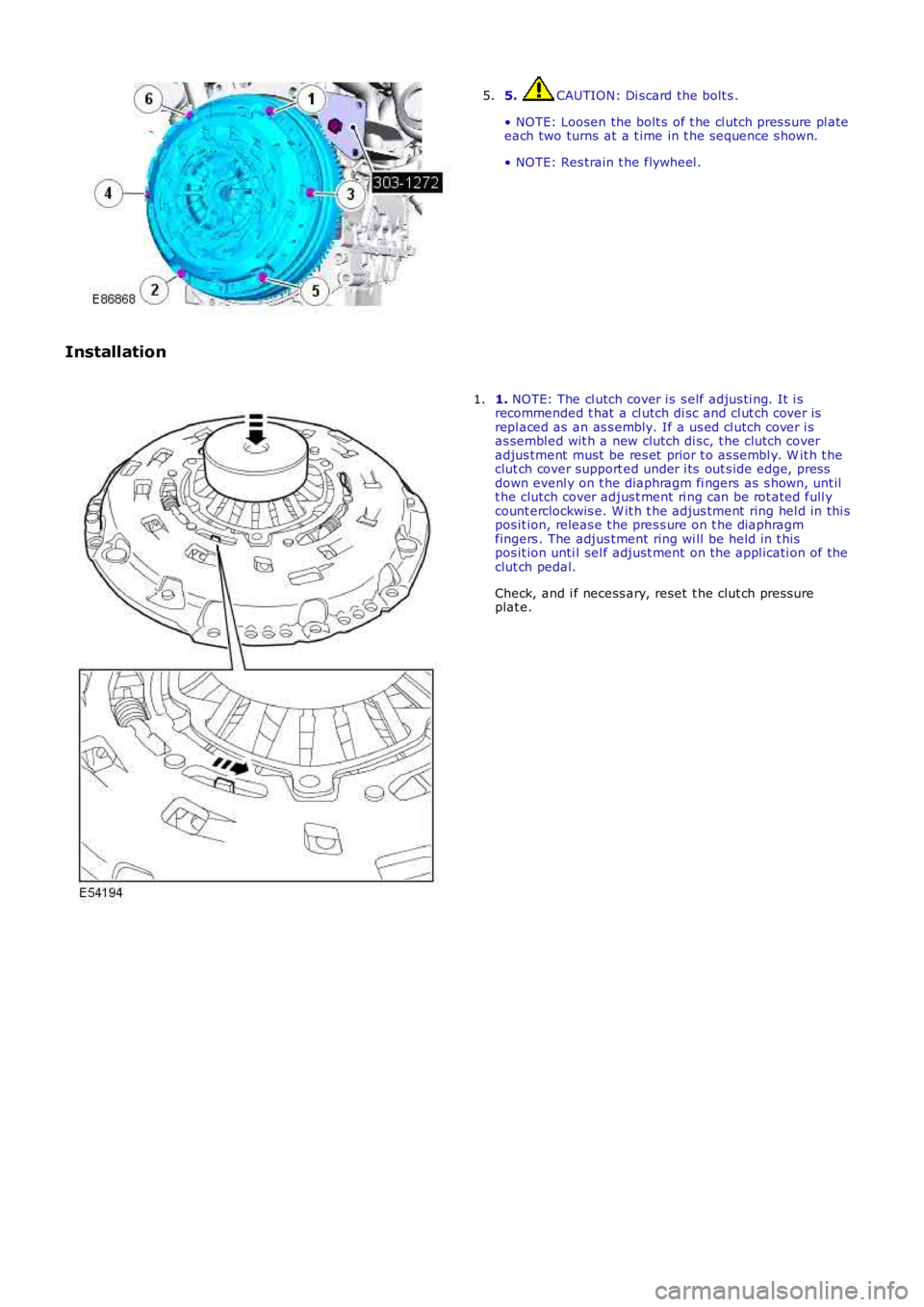
5. CAUTION: Di scard the bolt s .
• NOTE: Loosen the bolt s of t he cl utch pres s ure pl ateeach two turns at a t ime in t he s equence s hown.
• NOTE: Res train t he flywheel .
5.
Installation
1. NOTE: The cl utch cover i s s elf adjus ti ng. It i srecommended t hat a cl utch di sc and cl ut ch cover isrepl aced as an as s embly. If a us ed cl utch cover i sas sembl ed wit h a new clutch di sc, t he clutch coveradjus tment must be res et prior t o as sembl y. W it h t heclut ch cover support ed under i ts out s ide edge, pressdown evenl y on t he diaphragm fi ngers as s hown, unt ilt he clutch cover adjus t ment ri ng can be rot ated full ycount erclockwis e. W it h t he adjus tment ring hel d in thi spos it ion, releas e t he pres s ure on t he diaphragmfingers . The adjus tment ring wi ll be held in t hispos it ion unti l sel f adjust ment on t he appl icati on of theclut ch pedal.
Check, and i f necess ary, reset t he clut ch press ureplat e.
1.
Page 1795 of 3229
The current vehicle operat ing mode, s hown in parenthes is above, i s dis played in the odomet er for 5 s econds when t hevehi cl e first ent ers power mode 6.
• NOTE: 'Nor' is only di s pl ayed in t he Odometer when t he vehicle operat ing mode is changed t o normal from any of theother vehi cle operat ing modes . Under al l ot her condit ions , 'Nor' is not di spl ayed.
The vehi cl e operat ing mode can be changed us i ng the Land Rover approved di agnos ti c sys t em.
Gear Position
The gear pos it ion i ndicat or s hows the current aut omati c t ransmis s ion s elector l ever posi ti on. During normal operat ion thedis play wi ll s how P (park), R (revers e), N (neutral) and D (drive). W hen the t rans mis s ion is operat ed in 'CommandShi ft ™'mode, the odomet er di spl ays the current ly sel ect ed manual gear; 1, 2, 3, 4, 5 or 6.
In the event of eit her a CAN bus fai lure, or if t he TCM det ect s a t rans mi ss i on overheat s it uati on, t he odometer wi ll dis playt he let ter 'E' in the s ame area of t he dis play as t he 'CommandShift™' s elected gear informat ion.
Supplemental Restrain System Warning Indicator
If the i nst rument clus ter det ect s the Supplement al Res t raint Sys tem (SRS) warni ng indicator has fai led, t he mes sage 'SrS'wil l be dis played in the odomet er and a DTC s tored. The DTC can be ret rieved from the ins trument cl us t er us i ng the LandRover approved diagnost ic sys tem.
Service Interval Indicator
The Service Interval Indi cat or (SII) i nforms t he driver when t he next vehicle servi ce is due. The ins t rument clus ter monit orst he dis tance t he vehi cl e has travel ed and t he ti me el aps ed s ince t he las t s ervice.
If vehicle dis tance is the t rigger for the SII, 'SERVICE' will be di s pl ayed in t he odometer accompanied by a dis tancequal ifier (ei ther 'MILES' or 'KM' dependi ng on t he ins trument cl ust er s pecificati on). A di st ance counter wi ll als o be di s pl ayedin the t op Ri ght Hand (RH) corner of t he odometer. If t he point at which a servi ce is requi red is pas sed, t he count er wi lldis play a negat ive value. W hen acti vat ed, t he SII is di spl ayed for 5 s econds when t he vehi cl e enters power mode 6.
If ti me i s the trigger for the SII, 'SERVICE' wil l be di s pl ayed in t he odometer accompanied by a clock symbol . A count er willals o be di spl ayed i n t he t op RH corner of the odomet er. If t he point at which a s ervice is required is pas s ed, t he count erwil l dis play a negati ve val ue. Agai n, when act ivated t he SII is dis played for 5 s econds when t he vehi cl e enters power mode6.
If bot h t he dis tance and t ime triggers are acti vat ed, t he SII wil l di s pl ay the di s tance informat ion for 5 s econds, foll owedby t he ti me i nformati on for 5 s econds .
W hen a service has been carri ed out , t he SII wi ll need t o be re-s et. This can be done us ing t he Land Rover approveddiagnost ic s ys tem or foll owing a manual re-s et procedure. The manual re-s et mode is ent ered by carrying out the foll owingrout ine:
Pres s and hold the t ri p res et butt on wi th the vehicle st ati onary and in a power mode les s t han 6.W hi le holdi ng the trip res et but ton, enter t he vehi cl e int o power mode 6.Releas e the trip res et but ton wit hi n 10 s econds of entering power mode 6.
If the manual re-set mode has been s ucces s full y entered 'dISt ' or 'DATE' wi ll be di spl ayed i n t he odomet er, dependi ng onwhich t ri gger has been acti vat ed.
To clear the 'dISt ' trigger pres s, and hold the t rip reset but ton for more than 5 s econds wit hi n 10 s econds of entering t hemanual re-s et mode. If s ucces s ful, 'RESET' wil l be dis played in the odometer for 5 seconds. If t he dat e t ri gger has notbeen act ivated 'END' wil l t hen be dis played i n t he odomet er.
• NOTE: The dis t ance t ri gger wi ll not res et if t he dis t ance t he vehi cle has t raveled i s les s t han 20% of t he next s ervi ceint erval val ue.
If the dat e trigger has been act ivated, 'DATE' wil l be dis played in t he odometer. To clear the t ri gger, pres s and hold t het rip res et but t on for more t han 5 s econds wit hin 10 s econds of 'DATE' being di s pl ayed. If succes s ful , 'RESET' wi ll bedis played wit hin the odomet er for 5 s econds fol lowed by 'END'. The odomet er wil l now exit re-s et mode.
AMBIENT AIR TEMPERATURE
The ins t rument clus ter can dis play t he ambient air t emperature readi ng in ei ther degrees Cels ius or Fahrenhei t. Theambient air t emperat ure s ignal ori gi nat es i n the ambient air t emperature s ens or. The s ens or i s a Negati ve TemperatureCoefficient (NTC) t hermi st or, and i s mounted i n t he LH door mirror. A t emperature value i s cal cul ated by t he ECM andbroadcas t over the hi gh speed CAN bus to t he i ns t rument clus ter.
If the t emperat ure value fall s bel ow 4ºC (39ºF) t he mes sage center wi ll flas h the low ambi ent ai r temperat ure icon 5t imes . Thi s i s accompanied by a chime from the i nst rument clus t er s ounder. The low ambient air t emperature icon wi ll berepeated if t he ambient air t emperature ri s es above 6ºC (43ºF) t hen drops below 4ºC (39ºF) again or a new ignit ion cycleis st art ed.
Page 1827 of 3229
Publi s hed: 11-May-2011
Battery, Mounting and Cables -
General SpecificationItemSpecification
Battery - All models:
TypeExide H7Capaci ty80Ah/700CCA
Res erve capacit y125 minutes
Battery Disconnect/C onnect
CAUTION: The vehicle s t atus and batt ery condit ion mus t be es t abl is hed before att empti ng bat t erydis connect/connect . Reference mus t be t hen made t o t he fol lowing table to es t abl is h t he rel evant procedure t o befol lowed.
• NOTE: Vehicles fit ted wit h a fuel fired boos t er heat er will requi re a 5 mi nute wait before tel es t art funct ion wi ll operate.Cycl e t he ignit ion off->on->off. W ai t 5 mi nutes t o all ow fuel fired boos t er heat er to s t ore vehicle confi gurati onparamet ers .
Vehicle statusBattery chargedBattery discharged
ProcedureProcedure
Engine runni ng1Vehicle powered down, l ocked and alarmed23
Vehicle unl ocked45
Procedure 1
Disconnect batteryConnect battery1. Apply parki ng brake oralt ernat ively, chock wheels1. Ens ure that all el ect ri cal loads are s wit ched O FF
2. Swit ch off i gni ti on andremove the remote cont rol.2. Connect bat t ery l eads - GROUND lead l ast
3. W ai t 2 mi nut es for enginemanagement sys tem t o 'powerdown'
3. Swit ch on ignit ion
4. Open t he hood4. Reset radi o s tat ion preset but tons .
5. Dis connect batt ery - GROUNDl ead firs t5. Reset clock
6. Reset elect ric window one-t ouch facili ty. Power window up t o hard s top, rel eas es wit ch, reapply and hol d for 1 s econd (relay i n door wil l cl ick). Lower window t o s top,reapply and hold for one s econd. One t ouch s hould now work
Procedure 2
Disconnect batteryConnect battery
1. Unlock t he vehi cl e and dis armt he alarm us ing t he remotecont rol
1. Ensure t hat al l el ect ri cal l oads are s wit ched OFF
2. Apply parki ng brake oralt ernat ively, chock wheels2. Connect batt ery l eads - GROUND l ead las t
3. W ai t 2 mi nut es for enginemanagement sys tem t o 'powerdown'
3. Swit ch on i gni ti on
4. Open t he hood4. Res et radio s t ati on pres et but tons .
5. Dis connect batt ery - GROUNDl ead firs t5. Res et cl ock
6. Res et el ect ri c window one-touch facil it y. Power window up to hard s top, rel eases wit ch, reappl y and hold for 1 s econd (rel ay in door wil l cl ick). Lower window t o s top,reapply and hol d for one s econd. One t ouch should now work
• NOTE: 1. Disconnect battery - If the remot e cont rol is not funct ioning, it will be necess ary to manual ly unlock thevehi cl e us ing t he key.
Procedure 3
Disconnect batteryConnect battery1. Unlock t he vehi cl e from the LH frontdoor us i ng the key1. Ens ure t hat al l electrical l oads are s wi tched OFF
2. Enter t he vehi cl e, and dock t heremote control to si lence the al arm.2. Connect batt ery leads - GROUND l ead las t
3. Remove t he remot e cont rol and wai t2 minutes for engi ne managements yst em to 'power down'
3. Swi tch on i gni ti on
4. Open t he hood4. Res et radio st ati on pres et but t ons .
5. Dis connect batt ery - GROUND leadfirst5. Res et cl ock
6. Res et el ect ri c wi ndow one-touch facil it y. Power wi ndow up to hard s t op,release s wit ch, reapply and hol d for 1 second (relay i n door wil l cl ick). Lowerwi ndow to s top, reapply and hold for one s econd. One t ouch s hould now work
• NOTE: 1. Connect battery - If there is ins uffi cient capacit y in the bat tery to di s arm the al arm, t he alarm may sound onreconnect ion of t he bat t ery - St ep 2 wi ll dis arm t he alarm
Procedure 4
Disconnect batteryConnect battery
Page 2864 of 3229
Fuel and refuelling
144
L
RUNNING OUT OF FUEL
Note: If the vehicle does run out of fuel, a
minimum of 4 litres (0 .8 gallons) will be
required to restart the engine. The vehicle will
need to be driven 1.6-5 km (1-3 miles) in order
to reset the engine management and
monitoring systems.
Note: If the vehicle does run out of fuel,
seeking qualified assistance is advisable.
FUEL CUT-OFF
The fuel system cut-off forms part of the
Supplementary Restraint System (SRS) fitted
to your vehicle. Following an impact, and
depending on the severity, the fuel pump may
be switched off.
Resetting the fuel cut-off
1. Switch the ignition off and wait for one
minute.
2. Turn the ignition on for 30 seconds.
3. Check the vehicle thor oughly for fuel leaks.
If a leak is detected switch the ignition off
immediately.
• Do not start the vehicle if a leak is
present. Seek qualifi ed advice, and have
the vehicle recovered.
4. If no leaks are detected, start the vehicle.
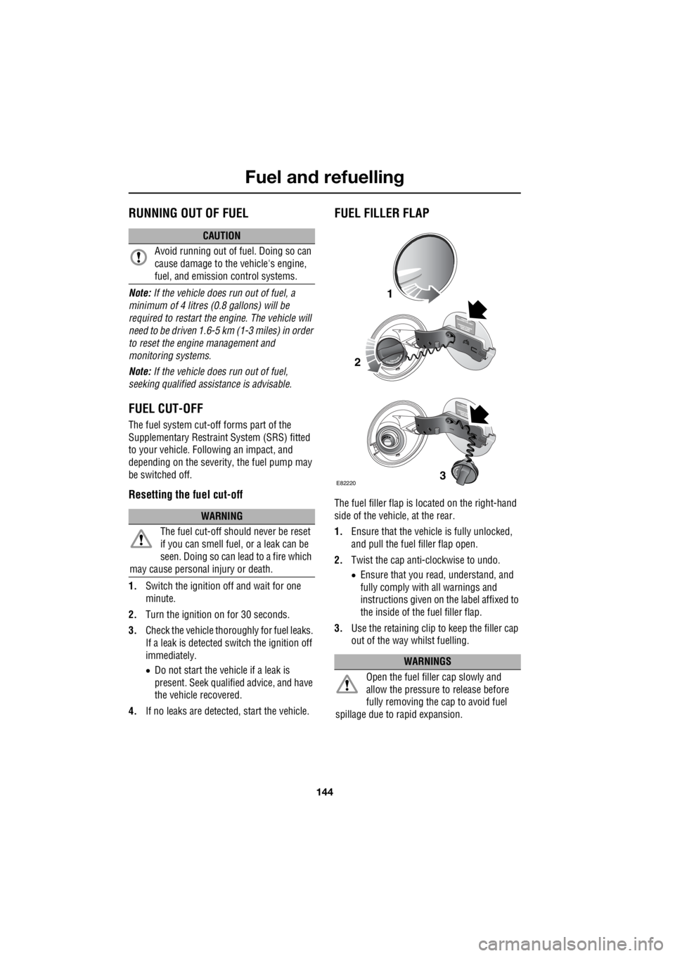
FUEL FILLER FLAP
The fuel filler flap is located on the right-hand
side of the vehicle, at the rear.
1. Ensure that the vehicle is fully unlocked,
and pull the fuel filler flap open.
2. Twist the cap anti-clockwise to undo.
• Ensure that you re ad, understand, and
fully comply with all warnings and
instructions given on the label affixed to
the inside of the fuel filler flap.
3. Use the retaining clip to keep the filler cap
out of the way whilst fuelling.
CAUTION
Avoid running out of fuel. Doing so can
cause damage to the vehicle's engine,
fuel, and emission control systems.
WARNING
The fuel cut-off s hould never be reset
if you can smell fuel , or a leak can be
seen. Doing so can lead to a fire which
may cause personal injury or death.
WARNINGS
Open the fuel filler cap slowly and
allow the pressure to release before
fully removing the cap to avoid fuel
spillage due to rapid expansion.
1
2
3E82220
Page 2948 of 3229
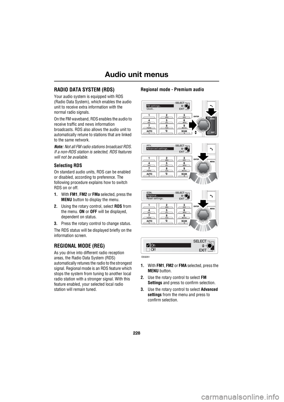
Audio unit menus
228
L
Audio unit menusRADIO DATA SYSTEM (RDS)
Your audio system is equipped with RDS
(Radio Data System), which enables the audio
unit to receive extra information with the
normal radio signals.
On the FM waveband, RD S enables the audio to
receive traffic and news information
broadcasts. RDS also al lows the audio unit to
automatically retune to stations that are linked
to the same network.
Note: Not all FM radio stat ions broadcast RDS.
If a non-RDS station is selected, RDS features
will not be available.
Selecting RDS
On standard audio unit s, RDS can be enabled
or disabled, according to preference. The
following procedure explains how to switch
RDS on or off.
1. With FM1, FM2 or FMa selected, press the
MENU button to display the menu.
2. Using the rotary control, select RDS from
the menu. ON or OFF will be displayed,
dependent on status.
3. Press the rotary control to change status.
The RDS status will be displayed briefly on the
information screen.
REGIONAL MODE (REG)
As you drive into diffe rent radio reception
areas, the Radio Data System (RDS)
automatically retunes the radio to the strongest
signal. Regional mode is an RDS feature which
stops the system from tuning to another local
radio station with a stronger signal. With this
feature enabled, your selected local radio
station will re main tuned.
Regional mode - Premium audio
1.With FM1, FM2 or FMA selected, press the
MENU button.
2. Use the rotary control to select FM
Settings and press to c onfirm selection.
3. Use the rotary control to select Advanced
settings from the menu and press to
confirm selection.
EXIT
SELECT
PTY..
Advanced settings..
EXIT
SELECT
EON..
Regional..
Reset settings..
EXIT
SELECTFM settings..
Clock..
On
Off
E83261
EXIT
SELECT
Page 2995 of 3229

Index
275
R
Preset buttons . . . . . . . . . . . . . . . . . . . . . 238 Recalling a preset channel . . . . . . . . . 239
Scrolling through presets . . . . . . . . . . 239
Storing channels as presets . . . . . . . . 238
Principle of operation Airbag deployment effects . . . . . . . . . . 61
Airbag operation . . . . . . . . . . . . . . . . . . 60
Airbags . . . . . . . . . . . . . . . . . . . . . . . . . 59
Before driving off-road . . . . . . . . . . . . 136
Brake pads . . . . . . . . . . . . . . . . . . . . . 123
Deployment and deflation . . . . . . . . . . . 60
Dynamic Stability Control (DSC) . . . . . 140
Gradient release control (GRC) . . . . . . 136
Introduction . . . . . . . . . . . . . . . . . . . . . 58
Roll stability control (RSC) . . . . . . . . . 140
Seat belt checks . . . . . . . . . . . . . . . . . . 55
Seat belt safety . . . . . . . . . . . . . . . . . . . 54
Seat belts . . . . . . . . . . . . . . . . . . . . . . . 54
Wet conditions . . . . . . . . . . . . . . . . . . 123
Priority programme type (PTY) . . . . . . . . 231 PTY search - Premium audio . . . . . . . 232
PTY seek - Standard audio . . . . . . . . . 233
PTY selection - Premium audio . . . . . 231Q
Quick start . . . . . . . . . . . . . . . . . . . . . . . . . . 7 Audio system . . . . . . . . . . . . . . . . . . . . . 27
Automatic transmission . . . . . . . . . . . . . 23
Bonnet . . . . . . . . . . . . . . . . . . . . . . . . . . . 9
CD autochanger . . . . . . . . . . . . . . . . . . . 30
CD OPERATION . . . . . . . . . . . . . . . . . . . 30
Clock setting . . . . . . . . . . . . . . . . . . . . . 31
Cruise control . . . . . . . . . . . . . . . . . . . . 24
DAB radio. . . . . . . . . . . . . . . . . . . . . . . . 29
Driving position memory . . . . . . . . . . . . 10
Engine starting . . . . . . . . . . . . . . . . . . . . . 8
Exterior lighting . . . . . . . . . . . . . . . . . . . 22
Facia. . . . . . . . . . . . . . . . . . . . . . . . . . . . 17
Gearshift interlocks . . . . . . . . . . . . . . . . 23
Heating and ventilation. . . . . . . . . . . . . . 14
Hill Descent Control (HDC) . . . . . . . . . . 25
Instrument pack . . . . . . . . . . . . . . . . . . . 19
Manual seat adjustment . . . . . . . . . . . . . 11
Master lock and unlock switches . . . . . . . 9
Overhead console . . . . . . . . . . . . . . . . . 12
Parking aid . . . . . . . . . . . . . . . . . . . . . . . 26
Passenger airbag deactivation . . . . . . . . 13
Power operated seat adjustment . . . . . . 10
Radio operation . . . . . . . . . . . . . . . . . . . 29
Remote control . . . . . . . . . . . . . . . . . . . . 7
Seat belts and Child restraints . . . . . . . . 13
Single CD player. . . . . . . . . . . . . . . . . . . 30
Steering column adjustment . . . . . . . . . 12
Steering column lock . . . . . . . . . . . . . . . 12
Tailgate . . . . . . . . . . . . . . . . . . . . . . . . . . 9
Telephone - Bluetooth system . . . . . . . . 31
Terrain Response system. . . . . . . . . . . . 25
Warning indicators (attention) . . . . . . . . 21
Warning indicators (information) . . . . . . 21
Windows and Door mirrors . . . . . . . . . . 11
Wipers and washers. . . . . . . . . . . . . . . . 22
R
Radio data system (RDS) . . . . . . . . . . . . . 228 Selecting RDS . . . . . . . . . . . . . . . . . . . 228
Radio reception . . . . . . . . . . . . . . . . . . . . 218
Rain sensor . . . . . . . . . . . . . . . . . . . . . . . . 87
Operation . . . . . . . . . . . . . . . . . . . . . . . . 88
Rear fog lamps . . . . . . . . . . . . . . . . . . . . . . 73