2006 LAND ROVER FRELANDER 2 weight
[x] Cancel search: weightPage 30 of 3229
Air condi ti oning unit s mus t not be li ft ed by t hei r hos es , pipes or capil lary li nes .Hos es and lines mus t not be s ubjected t o any t wis t or s tress ; t he efficiency of the s ys tem wil l be impai red by ki nksor res trict ions. Make s ure that hos es are correct ly pos it ioned before t ightening coupli ngs , and make s ure that allclips and support s are ut il is ed.Flexible hos es s houl d not be pos it ioned cl oser t han 100 mm (4.0 i n) t o t he exhaus t manifold unl es s protected byheat shi el ding.Complet ed ass embli es mus t be checked for refrigerat ion l ines t ouching met al panels . Any direct contact ofcomponents and panels may t rans mit nois e and s o must be el iminated.The appropri at e t orque wrench must be us ed when t ight eni ng refri gerant connect ions to t he s ti pul at ed value. Anaddi ti onal s panner mus t be us ed t o hold t he union t o prevent t wis ti ng of the pi pe when t ightening connect ions .Before connecti ng any hos e or pipe, make s ure that refri gerant oil is appli ed t o t he seat of t he new O-ri ngs , BUTNOT to the t hreads of the connect ion.All prot ect ive pl ugs or caps mus t remai n i n place in the component unt il i mmediat el y pri or to connect ion.Make s ure component s are at room temperat ure before uncappi ng/unpl uggi ng, t o prevent condens at ion of moi s turefrom the ai r that enters it .W hen di sconnect ing, immedi ately pl ug or cap all air condi ti oni ng pipes t o prevent ingres s of dirt and mois t ure i ntot he sys t em.Component s mus t not remain uncapped/unpl ugged, if a sys t em has been left uncapped/unpl ugged for 20 mi nut esor longer, a new recei ver/drier mus t be i ns t alled.The receiver/dri er contai ns des i ccant which absorbs mois t ure. It must be pos it ively sealed at al l ti mes . Areceiver/dri er t hat has been left uncapped for longer t han 20 mi nutes mus t not be used; i nst all a new uni t.The receiver/dri er s hould be the l ast component connect ed to the sys tem t o make s ure opt imum dehydrat ion andmaximum moi st ure protecti on of the sys tem.W henever a component of t he refrigerat ion s yst em is repl aced, it will al so be neces sary t o ins t al l a newreceiver/dri er uni t.Us e alcohol and a cl ean li nt -free cl oth to cl ean di rt y connecti ons.Make s ure t hat all new part s i ns t alled are marked for us e wit h R134a.W hen a major repai r has been complet ed, a leak t es t s hould be conduct ed; refer t o t he Repai rs Secti on of thi smanual for the correct procedure.
Refrigerant oil
CAUTION: Refrigerant oil eas il y absorbs water and mus t not be s tored for long periods. Do not pour unusedrefri gerant oi l back i nto the container. Always use an approved refrigerant oi l.
W hen replaci ng component s in the ai r condit ioning s ys tem, drai n t he refri gerant oi l from t he component being replacedint o a graduat ed cont ainer. On as s embly, add t he quant it y of refri gerant oi l drained t o t he new component - See Ai rCondi ti oni ng Compres s or Repl acement in this Sect ion.
Compres s or
A new compress or is sealed and press uris ed wit h Ni trogen gas . W hen i nst all ing a new compres sor, sl owly releas e thes eal ing cap; gas pres sure s houl d be heard to vent as t he s eal i s broken.
CAUTION: A new compress or s houl d always be s ealed and could be pres suris ed wit h ni trogen gas . To avoid pos si bleoil l os s , rel eas e t he s ealing cap(s ) s lowl y. Do not remove t he cap(s ) unt il i mmediatel y pri or to connect ing t he aircondi ti oni ng pipes t o the compress or.
Rapid refrigerant dis charge
If the ai r condit ioning s ys tem is i nvol ved in accident damage and t he s yst em is punct ured, t he refri gerant will di schargerapi dl y. The rapid di scharge of refrigerant wil l als o res ult in t he los s of mos t of the oi l from t he s yst em. The compres sormus t be removed and al l the remaining oi l in t he compres s or drained and refil led as i nst ruct ed in t he air condit ionings ect ion of t his manual.
Precaut ions for refrigerant recovery, recycl ing and rechargi ng
W hen t he air condit ioning s yst em is recharged, any exi s ti ng refri gerant i s first recovered from t he s ys t em and recycled.The s ys t em i s t hen charged wit h the required weight of refrigerant and volume of refrigerant oil .
W ARNING: Refri gerant mus t al ways be recycl ed before reus e t o make s ure that the purit y of the refrigerant i s highenough for s afe us e i n the ai r condit ioni ng sys t em. Recycl ing s hould al ways be carried out wit h equipment which i s des i gncert ifi ed by Underwrit er Laborat ory Inc. for compl iance wit h SAE J1991. Ot her equipment may not recycle refrigerant t o t herequired level of purit y.
• CAUTIO NS:
A R134a Refri gerant Recovery Recycli ng Rechargi ng Stat ion mus t not be us ed wit h any ot her t ype of refrigerant .Refrigerant R134a from domes ti c and commercial s ources mus t not be used i n mot or vehi cl e air condi ti oni ng s yst ems .
The s yst em must be evacuat ed i mmediat el y before recharging commences. Del ay bet ween evacuati on and rechargingis not permit ted.
Air Condit ioning Compress or Repl acement
A new compress or is suppli ed fi ll ed wit h a full charge (X cm³) of refrigerant oi l.
A calculat ed quant it y of oil mus t be drai ned from t he new compres s or before i nst all ing. To cal cul at e t he quant it y of oil t obe drai ned:
Remove the drain pl ug from the ol d compres sor.
Page 31 of 3229
Invert the compres s or and gravi ty drain the oi l into a calibrated meas uri ng cyl inder. Rotat e t he compres sor clut ch tomake s ure the compres s or is complet el y drai ned.Note the quanti ty of oi l drained (Y cm³).Calculate the quanti ty of oi l to be drained from t he new compres sor us ing t he fol lowi ng formula:X cm³ — (Y cm³ +20 cm³) = Q cm³Remove the drain pl ug from the new compres s or and drain Q cm3 of oi l. ins t al l and tight en t he compres sor drai nplug.
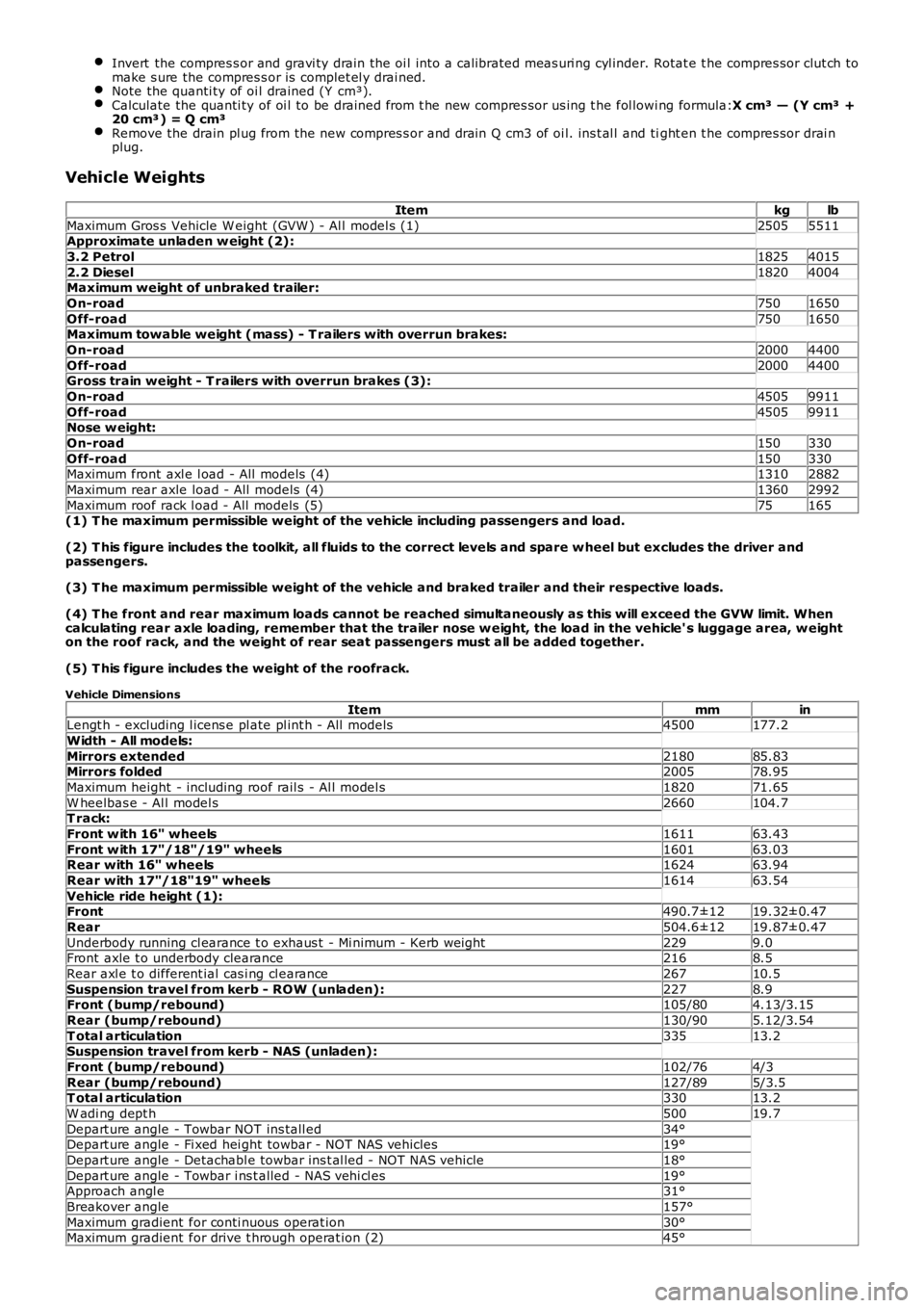
Vehicle Weights
Itemkglb
Maximum Gros s Vehicle W eight (GVW ) - Al l model s (1)25055511Approximate unladen w eight (2):
3.2 Petrol18254015
2.2 Diesel18204004Maximum weight of unbraked trailer:
On-road7501650
Off-road7501650Maximum towable weight (mass) - T railers with overrun brakes:
On-road20004400
Off-road20004400Gross train weight - T railers with overrun brakes (3):
On-road45059911
Off-road45059911Nose w eight:
On-road150330
Off-road150330Maximum front axl e l oad - All models (4)13102882
Maximum rear axle load - All models (4)13602992
Maximum roof rack l oad - All models (5)75165(1) T he maximum permissible weight of the vehicle including passengers and load.
(2) T his figure includes the toolkit, all fluids to the correct levels and spare w heel but excludes the driver andpassengers.
(3) T he maximum permissible weight of the vehicle and braked trailer and their respective loads.
(4) T he front and rear maximum loads cannot be reached simultaneously as this will exceed the GVW limit. Whencalculating rear axle loading, remember that the trailer nose w eight, the load in the vehicle' s luggage area, w eighton the roof rack, and the weight of rear seat passengers must all be added together.
(5) T his figure includes the weight of the roofrack.
Vehicle Dimensions
ItemmminLengt h - excluding l icens e pl ate pl int h - All models4500177.2
Width - All models:
Mirrors extended218085.83Mirrors folded200578.95
Maximum height - including roof rail s - Al l model s182071.65
W heelbas e - Al l model s2660104.7T rack:
Front w ith 16" wheels161163.43
Front w ith 17"/18"/19" wheels160163.03Rear with 16" wheels162463.94
Rear with 17"/18"19" wheels161463.54
Vehicle ride height (1):Front490.7±1219.32±0.47
Rear504.6±1219.87±0.47
Underbody running cl earance t o exhaus t - Mi nimum - Kerb wei ght2299.0Front axle t o underbody clearance2168.5
Rear axl e t o different ial cas i ng cl earance26710.5
Suspension travel from kerb - ROW (unladen):2278.9Front (bump/rebound)105/804.13/3.15
Rear (bump/rebound)130/905.12/3.54
T otal articulation33513.2Suspension travel from kerb - NAS (unladen):
Front (bump/rebound)102/764/3
Rear (bump/rebound)127/895/3.5T otal articulation33013.2
W adi ng dept h50019.7
Depart ure angle - Towbar NOT ins tall ed34°Depart ure angle - Fi xed hei ght towbar - NOT NAS vehicles19°
Depart ure angle - Detachabl e towbar ins t al led - NOT NAS vehicle18°
Depart ure angle - Towbar i ns t alled - NAS vehi cl es19°Approach angl e31°
Breakover angle157°
Maximum gradient for conti nuous operat ion30°Maximum gradient for drive t hrough operat ion (2)45°
Page 38 of 3229
Flammabl e - OBSERVE NO SMOKING POLICY .
Irrit at ion of t he mout h and t hroat may res ult from s wallowi ng. The main hazard from s wallowi ng ari ses if li qui d as pirat ionint o t he lungs occurs.
Liquid contact dri es the ski n and can caus e i rrit at ion or dermati ti s. Splas hes in the eye may be s light ly i rrit ati ng.
In normal circums t ances t he low vol ati lit y does not give ris e t o harmful vapors . Expos ure to mis t s and vapors fromkeros ene at el evat ed t emperature s houl d be avoi ded (mis ts may ari s e in dewaxing). Avoi d s ki n and eye cont act and makes ure t here i s adequat e vent il ati on.
If sw allow ed, DO NOT induce vomiting - SEEK IMMEDIAT E MEDICAL AT T ENT ION.
Gas Cylinders
Gas es such as oxygen, acet ylene, argon and propane are normall y s tored in cyli nders at pres s ures of up t o 138 bar (13800kPa) (2000 lbf/i n²) and great care should be taken i n handl ing t hese cyli nders t o avoi d mechani cal damage t o t hem or t ot he val ve gear at tached. The contents of each cylinder s houl d be clearl y ident ifi ed by appropri ate markings .
Cylinders should be s tored in wel l vent il at ed encl osures, and protected from ice and s now or direct sunli ght . Fuel gas es,for example acetyl ene and propane should not be st ored i n clos e proximit y t o oxygen cylinders .
Care should be exerci sed to prevent l eaks from gas cyl inders and l ines and als o t o avoid s ources of ignit ion.
Only trai ned pers onnel s houl d undertake work involving gas cyli nders .
General Workshop Tools and Equipment
It is es s ent ial t hat al l tools and equipment are maint ained in good condit ion and t he correct s afet y equi pment is us edwhere required.
Never us e t ools or equipment for any purpos e other t han that for whi ch they were desi gned. Never overl oad equi pments uch as hoi st s , jacks, axle and chas si s s tands or li ft ing sl ings . Damage caus ed by overloading i s not always immediatel yapparent and may res ult i n a fatal fai lure the next t ime that t he equi pment is us ed.
Do not us e damaged or defect ive t ools or equipment, part icularly hi gh s peed equipment s uch as gri ndi ng wheel s . Adamaged grindi ng wheel can dis int egrate wit hout warning and cause serious i njury.
W ear s uit abl e eye prot ect ion when us ing grinding, chis elli ng or s and bl ast ing equi pment .
W ear a s uit able breat hing mas k when us i ng abrasi ve blas ti ng equi pment or us i ng sprayi ng equi pment.
Make s ure t here i s adequat e vent il ati on to cont rol dust s , mis t s and fumes .
High Pressure Air, Lubrication and Oil Test Equipment
Always keep high press ure equi pment i n good condi ti on, and regul arly maint ai ned, parti cularly at joint s and uni ons.
Never di rect a high press ure nozzle, for example dies el i njector, at t he s kin as the fluid may penet rat e t o t he underlyingt is sue and caus e s eri ous i njury.
Jacking
Always refer to the Jacki ng and Lifti ng s ect ion of t hi s manual prior t o rai s ing t he vehi cl e off the ground.
W hen vehicle is t o be rais ed by means of a jack, ensure t hat i t is st andi ng on l evel ground, that parking brake is appli edand wheels are chocked. ALW AY S us e t he recommended jacking poi nt s and ens ure t hat vehi cl e jack has s ufficient loadcapacit y for t he weight of t he vehi cl e.
W ARNING: Do not work on or under a vehi cle s upported onl y by a jack. Always s upport t he vehi cl e on s afet y s tands .
Ensure t hat hois t s have s uffi ci ent load capacit y for t he wei ght of t he vehi cl e.
Legal Aspects
There are many l aws and regulat ions rel at ing to healt h and s afet y i n the us e and di spos al of materials and equipment i n aworks hop.
For a s afe worki ng envi ronment and t o avoi d environment al poll uti on, workshops s hould be famil iar, i n detai l, wi th t hemany healt h and s afety laws and regul ati ons wit hi n t hei r count ry, publ is hed by both nat ional and local aut horit ies .
Lubricants and Greases
Avoi d all prolonged and repeat ed contact wit h mi neral oils . All l ubricants and greases may be irri tat ing t o t he eyes ands ki n.
Used Engine Oil
Prol onged and repeat ed cont act wi th engi ne oil wil l res ult i n t he removal of nat ural fat s from the s kin, leading to drynes s ,irri tat ion and dermati ti s. In addit ion, used engi ne oil cont ains potent iall y harmful cont aminants whi ch may caus e s kincancer. Adequat e means of s kin protecti on and washi ng facil it ies mus t be provi ded.
Do not employ us ed engine oi ls as l ubricants or for any appli cat ion where appreciable s kin cont act i s li kel y t o occur.
Page 168 of 3229
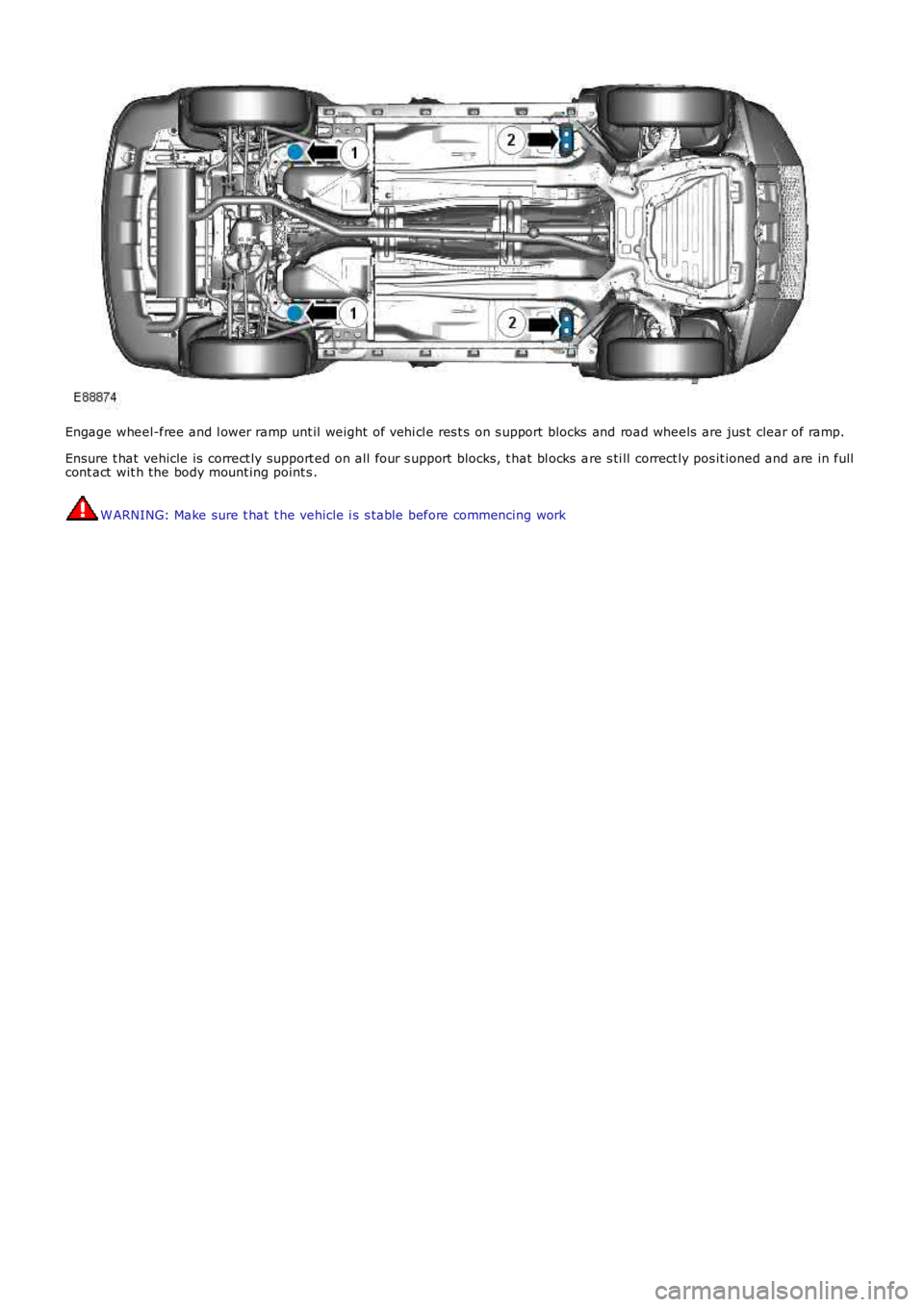
Engage wheel-free and l ower ramp unt il weight of vehi cl e res t s on s upport blocks and road wheels are jus t clear of ramp.
Ensure t hat vehicle is correct ly support ed on all four s upport blocks, t hat bl ocks are s ti ll correct ly pos it ioned and are in fullcont act wit h the body mount ing point s .
W ARNING: Make sure t hat t he vehicle i s s table before commencing work
Page 211 of 3229
Publi s hed: 11-May-2011
Front Suspension - Front Stabilizer Bar
Removal and Inst all ati on
Removal CAUTION: Nut s and bol ts mus t be ti ght ened wit h t he weight of t he vehi cl e on t he s us p
ensi on.
• NOTE: Only us e cl ean water as a l ubricant for t he bushi ng, i f required.
• NOTE: Removal s t eps in t his procedure may cont ain i nst all ati on det ail s.
1. W ARNING: Make sure t o s upport the vehicle wit h axle
s tands .
Rais e and s upport t he vehi cl e.
1.
Remove t he front wheel s and ti res .
Refer t o: W heel and Ti re (204-04 W heel s and Tires, Removal and
Inst all at ion).
2.
Remove t he dri ves haft .
Refer t o: Dri ves haft - Vehicles W it hout : Dies el Part icul ate Fi lt er (DPF) (205-01 Driveshaft, Removal and Ins tal lati on).
3.
Remove t he cat alyti c convert ers .
Refer t o: Cat alyt ic Converter (309-00A Exhaus t Syst em - I6 3.2L
Petrol, Removal and Ins tall ati on).
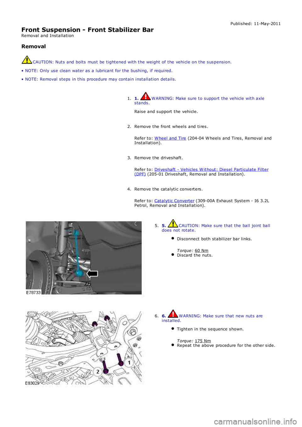
4. 5. CAUTION: Make s ure that the bal l joint ball
does not rot at e.
Di sconnect both st abili zer bar l inks.
T orque: 60 Nm Di scard the nut s.5.
6. W ARNING: Make sure t hat new nut s are
i ns t alled.
Tight en in the s equence s hown.
T orque: 175 Nm Repeat t he above procedure for t he other s ide.6.
Page 212 of 3229
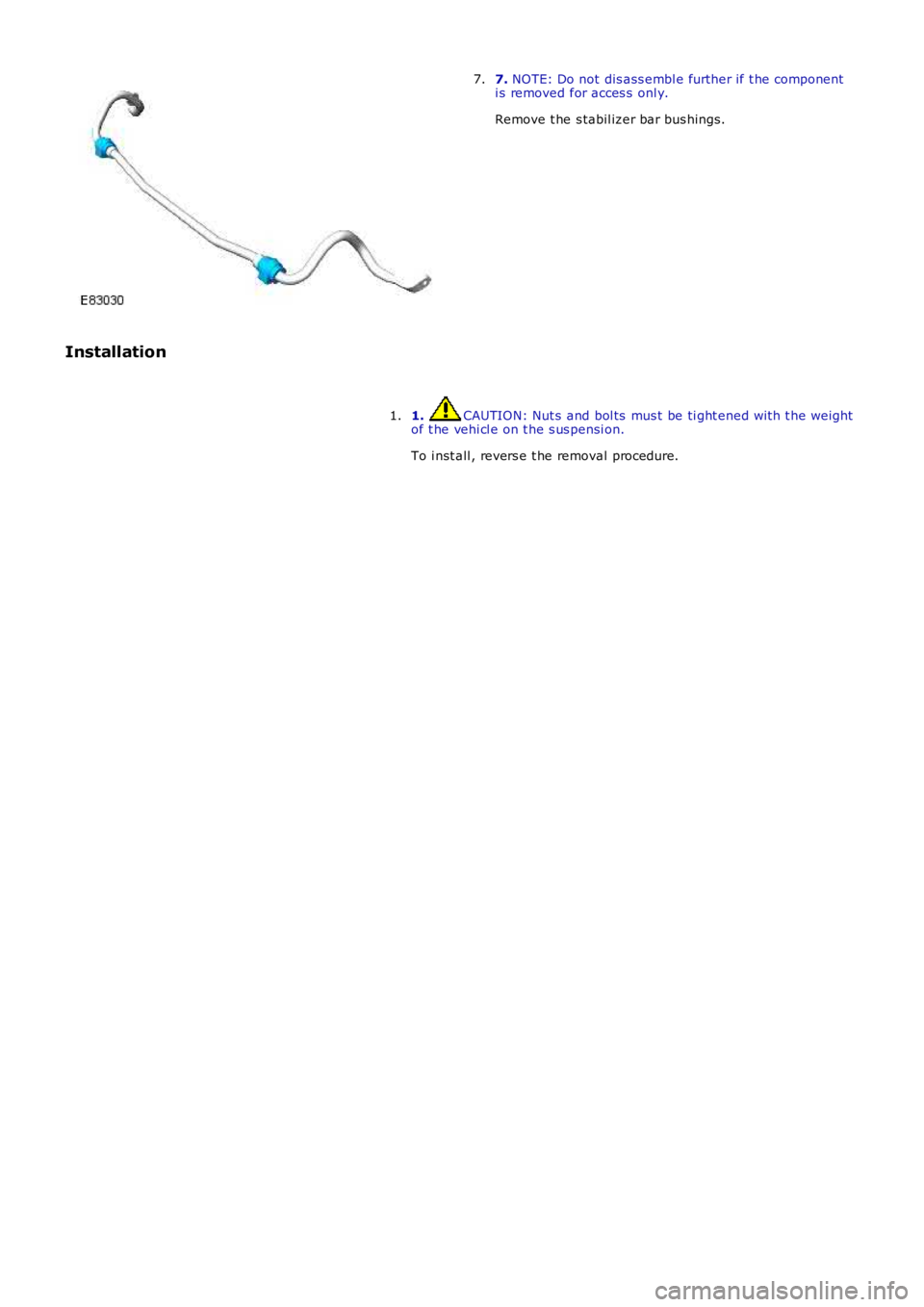
7. NOTE: Do not dis ass embl e further if t he componenti s removed for acces s onl y.
Remove t he s tabil izer bar bus hings.
7.
Installation
1. CAUTION: Nut s and bol ts mus t be ti ght ened wit h t he weightof t he vehi cl e on t he s us pensi on.
To i nst all , revers e t he removal procedure.
1.
Page 244 of 3229
6.
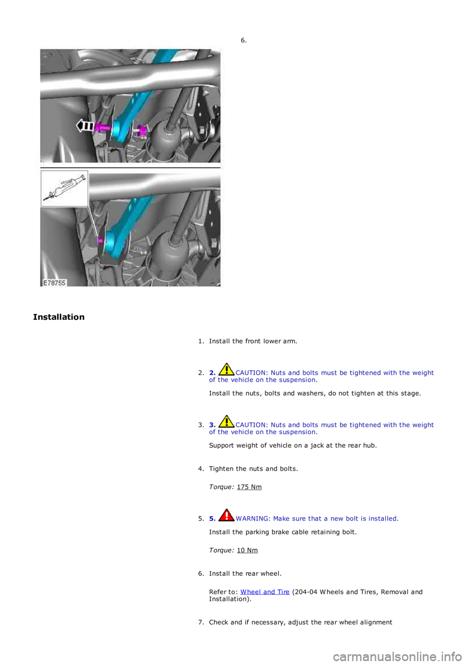
Installation Inst all t he front lower arm.
1.
2. CAUTION: Nut s and bol ts mus t be ti ght ened wit h t he weight
of t he vehi cl e on t he s us pensi on.
Inst all t he nut s , bol ts and washers, do not t ighten at this st age.
2.
3. CAUTION: Nut s and bol ts mus t be ti ght ened wit h t he weight
of t he vehi cl e on t he s us pensi on.
Support weight of vehi cl e on a jack at the rear hub.
3.
Tight en the nut s and bolt s.
T orque: 175 Nm 4.
5. W ARNING: Make sure t hat a new bolt i s ins tal led.
Inst all t he parking brake cable ret ai ning bolt .
T orque: 10 Nm 5.
Inst all t he rear wheel.
Refer t o: W heel and Ti re (204-04 W heel s and Tires, Removal and
Inst all at ion).
6.
Check and if neces s ary, adjus t the rear wheel ali gnment
7.
Page 246 of 3229
Publi s hed: 11-May-2011
Rear Suspension - Trailing Arm
Removal and Inst all ati on
Removal
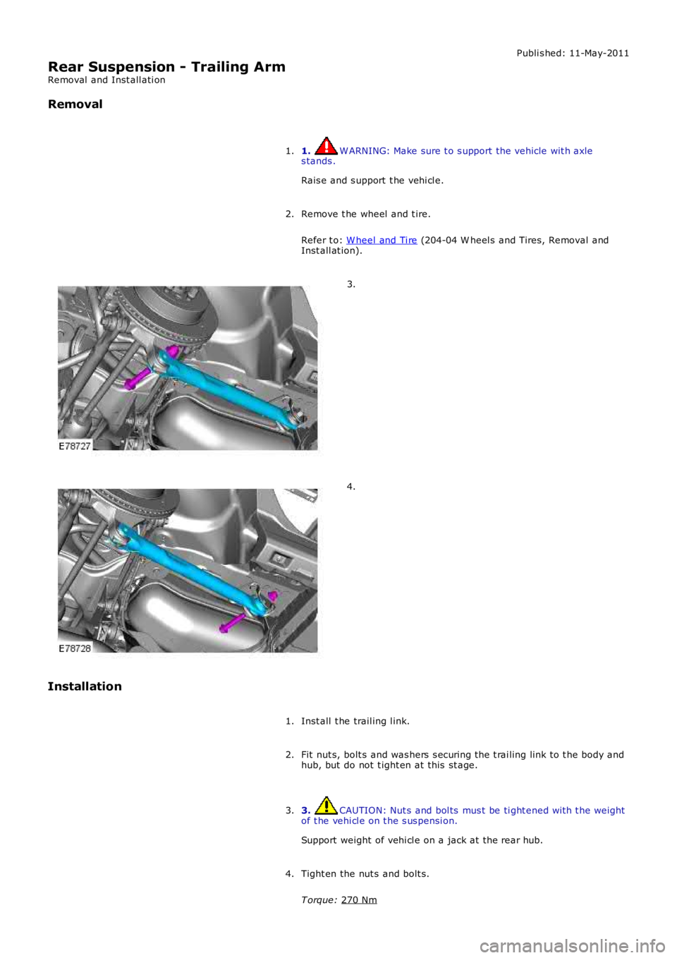
1. W ARNING: Make sure t o s upport the vehicle wit h axle
s tands .
Rais e and s upport t he vehi cl e.
1.
Remove t he wheel and t ire.
Refer t o: W heel and Ti re (204-04 W heel s and Tires, Removal and
Inst all at ion).
2. 3.
4.
Installation Inst all t he trail ing l ink.
1.
Fit nut s, bolt s and was hers s ecuring the t rai ling link to t he body and
hub, but do not t ight en at this st age.
2.
3. CAUTION: Nut s and bol ts mus t be ti ght ened wit h t he weight
of t he vehi cl e on t he s us pensi on.
Support weight of vehi cl e on a jack at the rear hub.
3.
Tight en the nut s and bolt s.
T orque: 270 Nm 4.