2006 LAND ROVER FRELANDER 2 water pump
[x] Cancel search: water pumpPage 61 of 3229
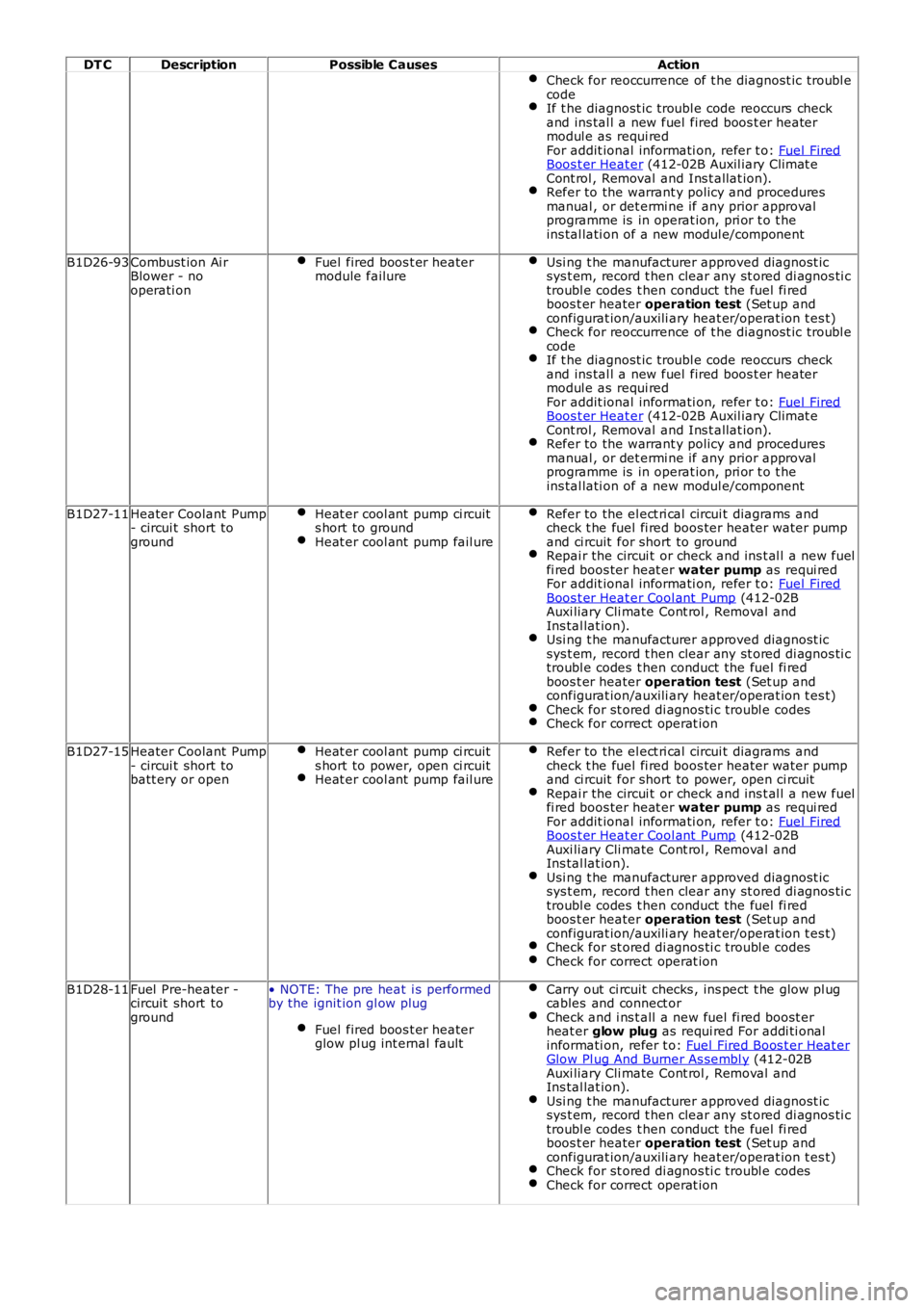
DT CDescriptionPossible CausesAction
Check for reoccurrence of t he diagnost ic troubl ecodeIf t he diagnost ic troubl e code reoccurs checkand ins tal l a new fuel fired boos t er heatermodul e as requi redFor addit ional informati on, refer t o: Fuel FiredBoos t er Heat er (412-02B Auxil iary Climat eCont rol , Removal and Ins t allat ion).Refer to the warrant y policy and proceduresmanual , or det ermi ne if any prior approvalprogramme is in operat ion, pri or t o t heins tal lati on of a new modul e/component
B1D26-93Combust ion Ai rBlower - nooperati on
Fuel fired boos t er heatermodule failureUsi ng t he manufacturer approved diagnost icsys t em, record t hen clear any st ored di agnos ti ctroubl e codes t hen conduct the fuel fi redboos t er heater operation test (Set up andconfigurat ion/auxili ary heat er/operat ion t es t)Check for reoccurrence of t he diagnost ic troubl ecodeIf t he diagnost ic troubl e code reoccurs checkand ins tal l a new fuel fired boos t er heatermodul e as requi redFor addit ional informati on, refer t o: Fuel FiredBoos t er Heat er (412-02B Auxil iary Climat eCont rol , Removal and Ins t allat ion).Refer to the warrant y policy and proceduresmanual , or det ermi ne if any prior approvalprogramme is in operat ion, pri or t o t heins tal lati on of a new modul e/component
B1D27-11Heater Coolant Pump- circui t short toground
Heat er cool ant pump ci rcuits hort to groundHeat er cool ant pump fail ure
Refer to the el ect ri cal circui t diagrams andcheck t he fuel fi red boos ter heater water pumpand ci rcuit for short to groundRepai r the circui t or check and ins t al l a new fuelfi red boos ter heat er water pump as requi redFor addit ional informati on, refer t o: Fuel FiredBoos t er Heat er Cool ant Pump (412-02BAuxi liary Cli mate Cont rol , Removal andIns tal lat ion).Usi ng t he manufacturer approved diagnost icsys t em, record t hen clear any st ored di agnos ti ctroubl e codes t hen conduct the fuel fi redboos t er heater operation test (Set up andconfigurat ion/auxili ary heat er/operat ion t es t)Check for st ored di agnos ti c troubl e codesCheck for correct operat ion
B1D27-15Heater Coolant Pump- circui t short tobatt ery or open
Heat er cool ant pump ci rcuits hort to power, open ci rcuitHeat er cool ant pump fail ure
Refer to the el ect ri cal circui t diagrams andcheck t he fuel fi red boos ter heater water pumpand ci rcuit for short to power, open ci rcuitRepai r the circui t or check and ins t al l a new fuelfi red boos ter heat er water pump as requi redFor addit ional informati on, refer t o: Fuel FiredBoos t er Heat er Cool ant Pump (412-02BAuxi liary Cli mate Cont rol , Removal andIns tal lat ion).Usi ng t he manufacturer approved diagnost icsys t em, record t hen clear any st ored di agnos ti ctroubl e codes t hen conduct the fuel fi redboos t er heater operation test (Set up andconfigurat ion/auxili ary heat er/operat ion t es t)Check for st ored di agnos ti c troubl e codesCheck for correct operat ion
B1D28-11Fuel Pre-heater -circuit short toground
• NOTE: The pre heat i s performedby the ignit ion gl ow plug
Fuel fired boos t er heaterglow pl ug int ernal fault
Carry out ci rcuit checks , ins pect t he glow pl ugcables and connect orCheck and i ns t all a new fuel fi red boost erheat er glow plug as requi red For addi ti onalinformati on, refer t o: Fuel Fired Boos t er Heat erGlow Pl ug And Burner As sembl y (412-02BAuxi liary Cli mate Cont rol , Removal andIns tal lat ion).Usi ng t he manufacturer approved diagnost icsys t em, record t hen clear any st ored di agnos ti ctroubl e codes t hen conduct the fuel fi redboos t er heater operation test (Set up andconfigurat ion/auxili ary heat er/operat ion t es t)Check for st ored di agnos ti c troubl e codesCheck for correct operat ion
Page 70 of 3229
Publi shed: 06-Jul-2011
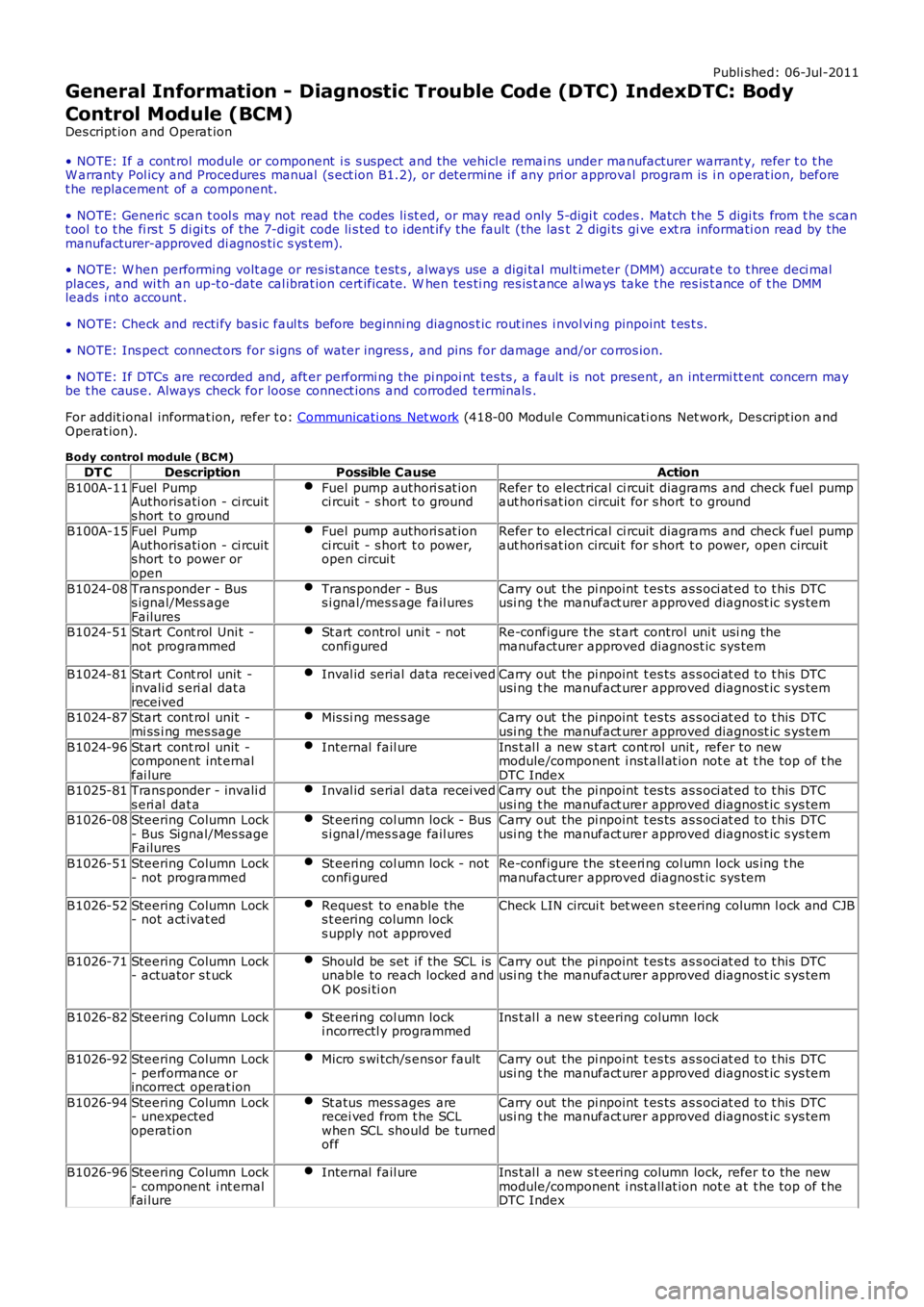
General Information - Diagnostic Trouble Code (DTC) IndexDTC: Body
Control Module (BCM)
Des cript ion and Operat ion
• NOTE: If a cont rol module or component i s s uspect and the vehicl e remai ns under manufacturer warrant y, refer t o t heW arranty Pol icy and Procedures manual (s ect ion B1.2), or determine i f any pri or approval program is i n operat ion, beforet he replacement of a component.
• NOTE: Generic scan t ool s may not read the codes li st ed, or may read only 5-digi t codes . Match t he 5 digi ts from t he s cant ool t o t he fi rs t 5 di gi ts of the 7-digit code li s ted t o i dent ify the fault (the last 2 digi ts gi ve ext ra informati on read by themanufacturer-approved di agnos ti c s ys t em).
• NOTE: W hen performing volt age or res is t ance t est s , always use a digi tal mult imeter (DMM) accurat e t o t hree deci malplaces, and wi th an up-t o-date cal ibrat ion cert ificate. W hen tes ti ng res is t ance al ways take t he res is t ance of t he DMMleads i nt o account .
• NOTE: Check and recti fy bas ic faul ts before beginni ng diagnos t ic rout ines i nvol vi ng pinpoint t es t s.
• NOTE: Ins pect connect ors for s igns of water ingres s , and pins for damage and/or corros ion.
• NOTE: If DTCs are recorded and, aft er performi ng the pi npoi nt tes ts , a fault is not present , an int ermi tt ent concern maybe t he caus e. Always check for loose connect ions and corroded terminals .
For addit ional informat ion, refer t o: Communicati ons Net work (418-00 Modul e Communicati ons Net work, Des cript ion andOperat ion).
Body control module (BC M)
DT CDescriptionPossible CauseAction
B100A-11Fuel PumpAuthoris ati on - ci rcuits hort t o ground
Fuel pump authori s at ionci rcuit - s hort t o groundRefer to electrical ci rcuit diagrams and check fuel pumpaut hori sat ion circui t for s hort t o ground
B100A-15Fuel PumpAuthoris ati on - ci rcuits hort t o power oropen
Fuel pump authori s at ionci rcuit - s hort t o power,open circui t
Refer to electrical ci rcuit diagrams and check fuel pumpaut hori sat ion circui t for s hort t o power, open circui t
B1024-08Trans ponder - Buss ignal/Mess ageFailures
Trans ponder - Buss i gnal /mes s age fail uresCarry out the pi npoint t es ts as s oci at ed t o t his DTCusi ng t he manufact urer approved diagnost ic s ys tem
B1024-51Start Cont rol Uni t -not programmedSt art control uni t - notconfi guredRe-configure the st art control uni t usi ng themanufacturer approved diagnost ic sys tem
B1024-81Start Cont rol unit -invali d s eri al dat areceived
Inval id serial data recei vedCarry out the pi npoint t es ts as s oci at ed t o t his DTCusi ng t he manufact urer approved diagnost ic s ys tem
B1024-87Start cont rol unit -mi ss i ng mes sageMis si ng mes s ageCarry out the pi npoint t es ts as s oci at ed t o t his DTCusi ng t he manufact urer approved diagnost ic s ys tem
B1024-96Start cont rol unit -component int ernalfai lure
Internal fail ureIns t al l a new s t art cont rol unit , refer to newmodule/component i nst all at ion not e at t he top of t heDTC IndexB1025-81Trans ponder - invali ds eri al dat aInval id serial data recei vedCarry out the pi npoint t es ts as s oci at ed t o t his DTCusi ng t he manufact urer approved diagnost ic s ys temB1026-08Steering Column Lock- Bus Signal/Mes sageFailures
St eering col umn lock - Buss i gnal /mes s age fail uresCarry out the pi npoint t es ts as s oci at ed t o t his DTCusi ng t he manufact urer approved diagnost ic s ys tem
B1026-51Steering Column Lock- not programmedSt eering col umn lock - notconfi guredRe-configure the st eeri ng col umn lock us ing t hemanufacturer approved diagnost ic sys tem
B1026-52Steering Column Lock- not act ivat edRequest to enable thes t eering column locks upply not approved
Check LIN circui t bet ween s teering column l ock and CJB
B1026-71Steering Column Lock- actuator s t uckShould be set i f the SCL isunable to reach locked andO K posi ti on
Carry out the pi npoint t es ts as s oci at ed t o t his DTCusi ng t he manufact urer approved diagnost ic s ys tem
B1026-82Steering Column LockSt eering col umn locki ncorrectl y programmedIns t al l a new s t eering column lock
B1026-92Steering Column Lock- performance orincorrect operat ion
Micro s wi tch/s ens or faultCarry out the pi npoint t es ts as s oci at ed t o t his DTCusi ng t he manufact urer approved diagnost ic s ys tem
B1026-94Steering Column Lock- unexpectedoperati on
St atus mes s ages arerecei ved from t he SCLwhen SCL should be turnedoff
Carry out the pi npoint t es ts as s oci at ed t o t his DTCusi ng t he manufact urer approved diagnost ic s ys tem
B1026-96Steering Column Lock- component i nt ernalfai lure
Internal fail ureIns t al l a new s t eering column lock, refer t o t he newmodule/component i nst all at ion not e at t he top of t heDTC Index
Page 500 of 3229
1
2
Publi s hed: 11-May-2011
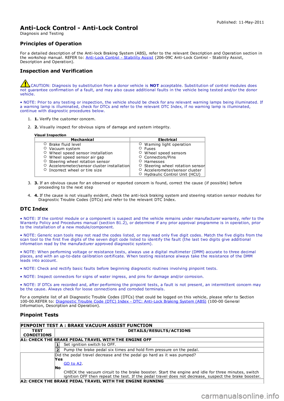
Anti-Lock Control - Anti-Lock Control
Diagnosi s and Tes ti ng
Principles of Operation
For a detail ed descripti on of the Ant i-lock Braking Sys t em (ABS), refer to the relevant Des cri pt ion and Operati on s ect ion i nt he works hop manual . REFER t o: Anti -Lock Cont rol - St abi li ty As s is t (206-09C Anti -Lock Cont rol - St abi lit y As s is t,Des cript ion and Operat ion).
Inspection and Verification
CAUTION: Di agnos is by s ubs ti tut ion from a donor vehicle is NO T acceptabl e. Subs ti tut ion of cont rol modules doesnot guarant ee confirmat ion of a faul t, and may als o caus e addit ional fault s i n t he vehi cl e being t est ed and/or t he donorvehi cl e.
• NOTE: Pri or to any t es ti ng or ins pect ion, the vehicle should be check for any relevant warning l amps bei ng il lumi nat ed. Ifa warning l amp is ill uminat ed, check for DTCs and refer to t he relevant DTC Index, if no warni ng lamp is i ll uminated,cont inue wi th diagnos t ic procedures below.
1. Verify t he cus t omer concern.1.
2. Vis ually ins pect for obvious s igns of damage and s ys t em i ntegri ty.
Visual InspectionMechanicalElectrical
Brake flui d levelVacuum s ys t emW heel s peed sens or ins tall ati onW heel s peed sens or ai r gapSt eering wheel rot ati on sens orAccel erometer/s ens or clus t er i nst all ati onIncorrect wheel or t ire s ize
W arning light operat ionFus esW heel s peed s ens orsConnect ors /Pi nsHarnes s esSt eering wheel rot ati on s ens orAccel eromet er/sens or cl ust erHydraul ic Control Uni t (HCU)
2.
3. If an obvious cause for an obs erved or report ed concern is found, correct t he caus e (if pos s ible) beforeproceeding t o t he next s t ep3.
4. If t he caus e is not vis ually evi dent , check t he ant i-lock braking sys tem and s teering rot ati on s ens or modules forDi agnos ti c Trouble Codes (DTCs) and refer t o t he rel evant DTC Index.4.
DTC Index
• NOTE: If the control modul e or a component i s s us pect and the vehicle remains under manufacturer warrant y, refer t o theW arranty Pol icy and Procedures manual (s ect ion B1.2), or determine i f any pri or approval programme is in operat ion, pri ort o the ins tall ati on of a new module/component.
• NOTE: Generic scan t ool s may not read the codes li st ed, or may read only fi ve digit codes . Mat ch the five di git s from t hes can tool to the firs t fi ve di git s of the seven digi t code l is ted to ident ify t he faul t (t he las t t wo digi ts gi ve addi ti onalinformat ion read by the manufact urer approved diagnos t ic s ys tem).
• NOTE: W hen performing volt age or res is t ance t est s , always use a digi tal mult imeter (DMM) accurat e t o t hree deci malplaces, and wi th an up-t o-date cal ibrat ion cert ificate. W hen tes ti ng res is t ance al ways take t he res is t ance of t he DMMleads i nt o account .
• NOTE: Check and recti fy bas ic faul ts before beginni ng diagnos t ic rout ines i nvol vi ng pinpoint t es t s.
• NOTE: Ins pect connect ors for s igns of water ingres s , and pins for damage and/or corros ion.
• NOTE: If DTCs are recorded and, aft er performi ng the pi npoi nt tes ts , a fault is not present , an int ermi tt ent concern maybe t he caus e. Always check for loose connect ions and corroded terminals .
For a compl ete lis t of all Di agnos ti c Trouble Codes (DTCs) t hat could be logged on this vehicle, pleas e refer to Sect ion100-00.REFER t o: Di agnos t ic Trouble Code (DTC) Index - DTC: Ant i-Lock Braki ng Sys t em (ABS) (100-00 GeneralInformat ion, Des cript ion and Operat ion).
Pinpoint Tests
PINPOINT TEST A : BRAKE VACUU M ASSIST FU NCTION
T ESTCONDIT IONSDET AILS/RESULT S/ACT IO NS
A1: CHECK T HE BRAKE PEDAL T R AVEL WIT H T HE ENGINE OFF
Set i gnit ion s wit ch t o OFF.
Pump t he brake pedal s ix ti mes and hold firm press ure on t he pedal .
Did t he pedal t ravel decreas e and t he pedal go hard as i t was pumped?YesGO t o A2.NoCHECK the vacuum circui t to the brake boos t er. Start the engine and idle for three mi nut es, s wi tchignit ion OFF t hen repeat t he tes t. If t he pedal t ravel does not decreas e, s uspect the brake boos t er.
A2: CHECK T HE BRAKE PEDAL T R AVEL WIT H T HE ENGINE RUNNING
Page 755 of 3229
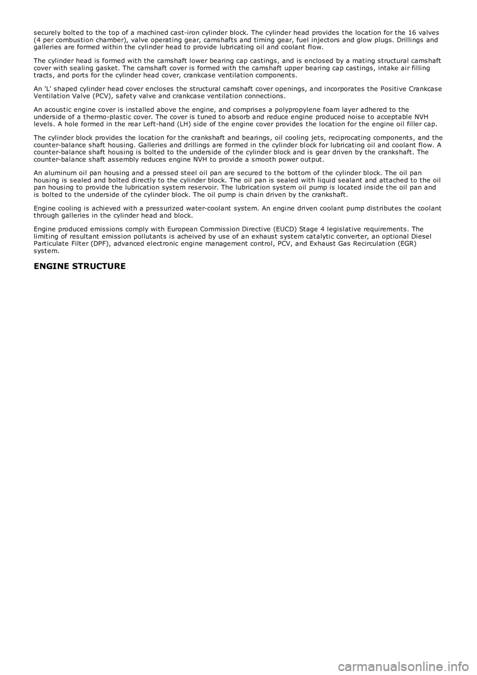
s ecurel y bolt ed to the top of a machined cas t-iron cyl inder block. The cylinder head provides t he locati on for t he 16 valves(4 per combus ti on chamber), valve operat ing gear, cams haft s and ti ming gear, fuel inject ors and glow plugs. Dril li ngs andgalleries are formed wi thi n the cyli nder head t o provide lubri cat ing oi l and coolant fl ow.
The cyl inder head is formed wit h the cams haft l ower bearing cap cas t ings , and is enclos ed by a mat ing s t ructural cams haftcover wi th s eali ng gasket. The cams haft cover i s formed wi th the cams haft upper beari ng cap cas t ings , intake ai r fil li ngt racts , and port s for t he cyl inder head cover, crankcas e venti lat ion component s.
An 'L' s haped cyli nder head cover enclos es the s t ructural cams haft cover openings, and i ncorporates t he Posi ti ve Crankcas eVenti lati on Valve (PCV), s afet y val ve and crankcas e vent il ati on connecti ons .
An acous t ic engine cover i s i ns t alled above t he engi ne, and compris es a polypropylene foam layer adhered to theunders ide of a t hermo-plas ti c cover. The cover i s t uned t o abs orb and reduce engine produced nois e t o accept abl e NVHlevels . A hole formed in the rear Left-hand (LH) s ide of t he engine cover provi des the l ocat ion for the engine oi l fil ler cap.
The cyl inder block provides t he locat ion for t he cranks haft and beari ngs , oil cooling jet s, reci procat ing component s , and thecount er-bal ance s haft hous ing. Galleries and drill ings are formed in the cyli nder block for lubri cat ing oi l and coolant fl ow. Acount er-bal ance s haft hous ing i s bolt ed to the unders ide of t he cylinder block and is gear dri ven by the cranks haft . Thecount er-bal ance s haft as s embly reduces engine NVH to provi de a s moot h power out put .
An aluminum oi l pan hous ing and a pres sed st eel oi l pan are s ecured t o t he bot t om of t he cyl inder bl ock. The oil panhous i ng is s ealed and bol ted di rectl y to the cyli nder block. The oil pan is sealed wit h li qui d s ealant and att ached t o t he oilpan hous i ng to provide t he lubricat ion sys tem res ervoir. The lubricat ion sys tem oil pump i s l ocated ins ide t he oil pan andis bol ted t o t he unders ide of t he cyl inder bl ock. The oil pump is chain driven by t he cranks haft .
Engi ne cool ing i s achi eved wit h a pres s uri zed water-cool ant sys tem. An engi ne dri ven coolant pump dis t ri but es t he cool antt hrough gal leries in the cyli nder head and block.
Engi ne produced emis s ions comply wi th European Commis s ion Di recti ve (EUCD) St age 4 legis l at ive requirement s . Theli mit ing of res ul tant emi ss i on pol lut ant s i s acheived by us e of an exhaus t s yst em cat alyti c convert er, an opt ional Di eselPart iculate Filt er (DPF), advanced el ect ronic engine management cont rol , PCV, and Exhaus t Gas Recircul at ion (EGR)s ys t em.
ENGINE STRUCTURE
Page 994 of 3229

chambers. Thi s provides opti mum performance, all owing t he engi ne t o be extremely respons ive t o dri ver demands for al ldri vi ng condi ti ons . The fuel s yst em features a Bos ch Generat ion 3 common rai l injection s yst em that is moni tored andcont rol led by an engine control modul e (ECM), t o precis ely cont rol the fueli ng st rategy.
Fuel charging is achieved wit h a l ow and hi gh-pres sure fuel s yst em. The l ow-pres s ure fuel s ys tem compris es ;
a s addle t ype fuel tankt ank mount ed fuel deli very module wi th int egral trans fer pumpfuel s uppl y and ret urn linesfi lt er and water s eparator as sembl ya connect ing hos e between t he fuel filt er ass embly and the fuel lift pump.
• NOTE: The fuel l ift pump is i ntegral wi th the hi gh-pres s ure pump.
A return li ne and fuel leak off hos es from the hi gh-pres s ure pump, i nject ors and common fuel rai l form t he remai nder oft he low-pres sure fuel ret urn ci rcuit .For addit ional informat ion, refer t o: Fuel Tank and Lines - 2.2L Duratorq-TDCi (DW ) Dies el (310-01 Fuel Tank and Li nes ,Des cript ion and Operat ion).
The high-press ure fuel s ys t em compri s es ;
a hi gh-pres sure fuel pumpcommon fuel rail4 pi ezo-injectors wit h hi gh-pres s ure connecti on pipesa fuel press ure sens or.
The fuel charging and control s ys tem provides i nject ion press ures of up to 1800 bar (26,106 psi ). Fi ner at omizati on of theinject ed fuel is achieved wi th the 7 hol e piezo i njectors that are capable of near ins tant aneous res ponse to the ECMcommands , all owing up to 5 individual inject ions per st roke.
The high-press ure fuel pump i s mounted at t he rear of t he cyl inder head and i s dri ven by the exhaust cams haft . A fuel l iftpump i s int egral wit h t he high-pres s ure pump and is therefore al so driven when t he exhaus t cams haft rot ates . The li ftpump creat es suct ion i n the supply line to t he fuel t ank and draws t he fuel from the t ank. The fuel pas s es through the fuelfi lt er and is t hen delivered at lift pump pres s ure to the hi gh-pres sure pump i nlet port .
The advanced high-press ure fueli ng s ys t em enables pil ot inject ions to be delivered ahead of t he main charge of fuel. Thisproduces a s teady fl ame front and creates a progres s ive pres s ure ris e in t he cyl inder s imi lar to that achi eved wit h petrolengi nes. This reduct ion i n combust ion lag between t he i nject ion of fuel and combus tion occurring al lows fuel t o be i njectedwhil e combus t ion i s t aki ng place, creat ing i ncreas ed power and reducing creat ed combus t ion nois e, vibrat ion andhars hnes s (NVH) and emis s ions .
For model s fi tt ed wi th an exhaus t sys t em dies el parti cul ate fil ter, the hi gh-pres s ure fueling sys tem als o provi des pos tcombus t ion i njecti on of fuel into the combus ti on chambers. W hen regenerati on of the di esel part iculat e fi lt er is reques t ed,t he ECM all ows the fueli ng s ys t em t o deli ver fuel after t he combus t ion s troke and int o t he commencement of the exhausts troke. This pos t combus t ion i njecti on proces s caus es fuel to be burnt in the exhaust s ys tem and creates t he high exhaus tgas temperatures that are required to regenerate t he dies el part icul ate fi lt er.
Page 996 of 3229
Dies el, Des cript ion and Operat ion).
Fuel i njecti on pres sure is generat ed i ndependent ly of engine s peed and fuel inject ion events . The HP fuel s ys tem iscont rol lable t o t he opti mum level for smoot h operat ion, and is capabl e of devel opi ng an i nject ion press ure up t o 1,600 bar(23,206 psi ). The fuel i njecti on ti ming and vol ume are cal cul at ed by t he ECM t hat als o energizes t he appropriat e piezo-act uated i njector.
The fuel s yst em features a pre-inject ion (pilot ) phas e t o reduce combus ti on noi s e and mechani cal load. On vehiclesins t al led wi th a Di es el Part iculate Fi lt er (DPF), t he fuel s ys tem als o provides a pos t -i nject ion phas e t hat is requi red forregenerat ing t he DPF.For addit ional informat ion, refer t o: Exhaus t Sys t em (309-00B Exhaus t Syst em - TD4 2.2L Di es el, Des cri pt ion andOperat ion).
This t ype of fuel sys t em all ows t he TD4 engi ne t o achi eve excellent l evels of performance and engine res pons e, whilebeing able to meet current and fut ure exhaus t emi s si on legis l at ion.
Fuel charging is achieved wit h a LP and HP fuel s ys t em. The LP fuel s yst em compris es:
Saddl e t ype fuel tankTank mount ed fuel deli very module and integral t rans fer pumpFuel s upply and return li nesFil ter and water s eparator as s embly.For addit ional informat ion, refer t o: Fuel Tank and Lines (310-01B Fuel Tank and Lines - TD4 2.2L Dies el ,Des cript ion and Operat ion).
The HP fuel s ys tem compris es :
HP fuel pump wit h int egral mounted l ift pump and Volume Cont rol Valve (VCV)Common fuel rail wi th integral PCV and press ure s ens or4 pi ezo-injectorsHP connect ing pipesFuel l eak-off pipes .
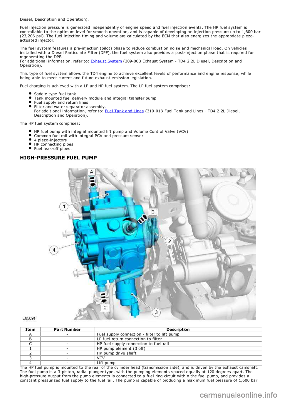
HIGH-PRESSURE FUEL PUMP
ItemPart NumberDescription
A-Fuel supply connect ion - fil ter t o l ift pumpB-LP fuel return connecti on t o fi lt er
C-HP fuel s upply connect ion to fuel rail
1-HP pump element (3 off)2-HP pump dri ve s haft
3-VCV
4-Li ft pumpThe HP fuel pump is mount ed to the rear of t he cylinder head (t rans mi ss ion si de), and is driven by t he exhaus t cams haft.The fuel pump i s a 3-pis ton, radi al pl unger type, wit h t he pumping el ement s s paced equall y at 120 degrees apart. Thehigh-press ure out put from t he pump el ement s i s connected t o a fuel ri ng ci rcuit wi thi n t he fuel pump, and provi des acons t ant press uri zed fuel s upply to the fuel rail . The pump is capable of producing a maxi mum fuel pres sure of 1,600 bar
Page 1221 of 3229
Symptom(general)Symptom (specific)Possible causesAction
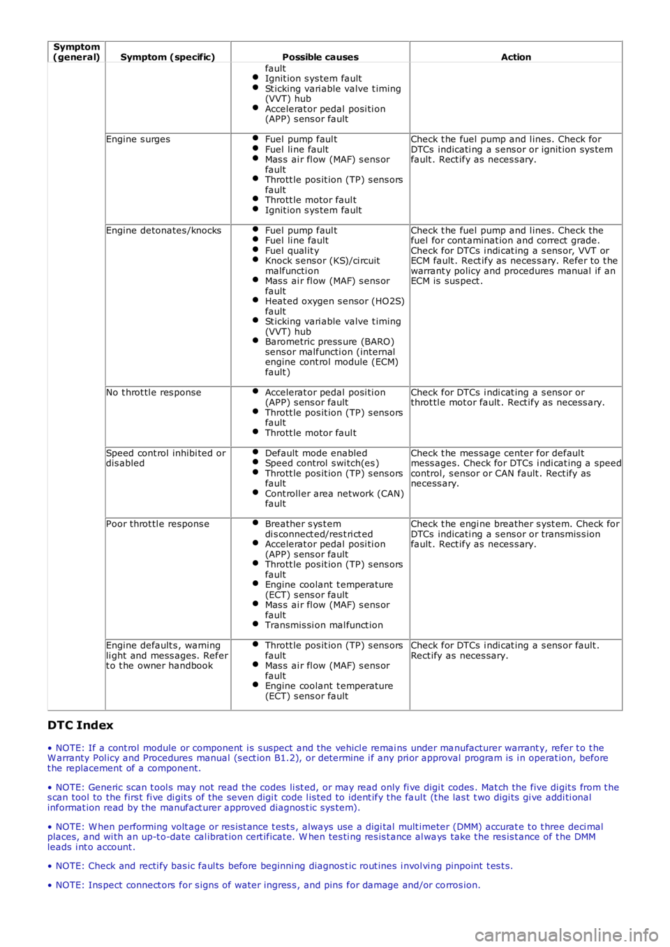
faultIgnit ion s ys tem faultSt icking vari able valve t iming(VVT) hubAccelerat or pedal posi ti on(APP) s ens or fault
Engine s urgesFuel pump faul tFuel li ne faultMas s ai r fl ow (MAF) s ens orfaultThrott le pos it ion (TP) s ens orsfaultThrott le motor faul tIgnit ion s ys tem fault
Check t he fuel pump and l ines. Check forDTCs indicati ng a s ens or or ignit ion sys temfault . Rect ify as neces s ary.
Engine detonates /knocksFuel pump faul tFuel li ne faultFuel qual it yKnock s ens or (KS)/ci rcuitmalfuncti onMas s ai r fl ow (MAF) s ens orfaultHeat ed oxygen s ensor (HO2S)faultSt icking vari able valve t iming(VVT) hubBarometric press ure (BARO)sens or malfuncti on (internalengine cont rol module (ECM)fault )
Check t he fuel pump and l ines. Check thefuel for cont aminat ion and correct grade.Check for DTCs i ndi cat ing a s ens or, VVT orECM fault . Rect ify as neces s ary. Refer t o t hewarrant y policy and procedures manual if anECM is sus pect .
No t hrot tl e res ponseAccelerat or pedal posi ti on(APP) s ens or faultThrott le pos it ion (TP) s ens orsfaultThrott le motor faul t
Check for DTCs i ndi cat ing a s ens or orthrot tl e mot or fault . Rect ify as neces s ary.
Speed cont rol inhibi ted ordis abledDefault mode enabledSpeed control s wi tch(es )Thrott le pos it ion (TP) s ens orsfaultCont roll er area network (CAN)fault
Check t he mes sage center for defaul tmess ages. Check for DTCs i ndi cat ing a speedcontrol, s ensor or CAN fault . Rect ify asnecess ary.
Poor throt tl e respons eBreather s ys t emdi s connect ed/res t ri ct edAccelerat or pedal posi ti on(APP) s ens or faultThrott le pos it ion (TP) s ens orsfaultEngine coolant t emperature(ECT) s ens or faultMas s ai r fl ow (MAF) s ens orfaultTransmis si on mal funct ion
Check t he engi ne breather s yst em. Check forDTCs indicati ng a s ens or or transmis s ionfault . Rect ify as neces s ary.
Engine default s , warningli ght and mess ages. Refert o t he owner handbook
Thrott le pos it ion (TP) s ens orsfaultMas s ai r fl ow (MAF) s ens orfaultEngine coolant t emperature(ECT) s ens or fault
Check for DTCs i ndi cat ing a s ens or fault .Rect ify as neces sary.
DTC Index
• NOTE: If a cont rol module or component i s s uspect and the vehicl e remai ns under manufacturer warrant y, refer t o t heW arranty Pol icy and Procedures manual (s ect ion B1.2), or determine i f any pri or approval program is i n operat ion, beforet he replacement of a component.
• NOTE: Generic scan t ool s may not read the codes li st ed, or may read only fi ve digit codes . Mat ch the five di git s from t hes can tool to the firs t fi ve di git s of the seven digi t code l is ted to ident ify t he faul t (t he las t t wo digi ts gi ve addi ti onalinformat ion read by the manufact urer approved diagnos t ic s ys tem).
• NOTE: W hen performing volt age or res is t ance t est s , always use a digi tal mult imeter (DMM) accurat e t o t hree deci malplaces, and wi th an up-t o-date cal ibrat ion cert ificate. W hen tes ti ng res is t ance al ways take t he res is t ance of t he DMMleads i nt o account .
• NOTE: Check and recti fy bas ic faul ts before beginni ng diagnos t ic rout ines i nvol vi ng pinpoint t es t s.
• NOTE: Ins pect connect ors for s igns of water ingres s , and pins for damage and/or corros ion.
Page 1629 of 3229
Publi shed: 06-Jul-2011
Climate Control System - General Information - Climate Control System
Diagnosi s and Tes ti ng
Principles of Operation
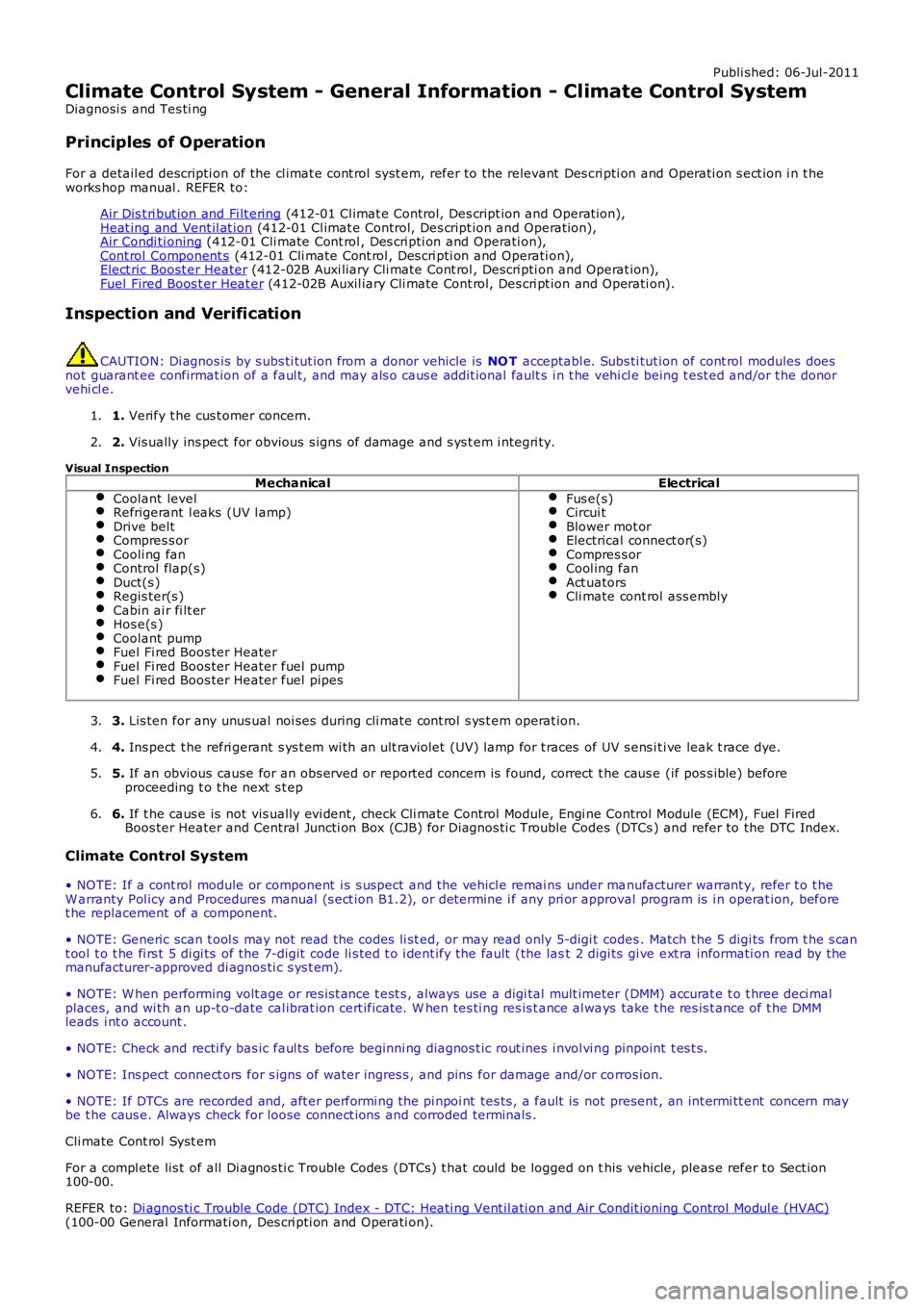
For a detail ed descripti on of the cl imat e cont rol s yst em, refer to the relevant Des cri pti on and Operati on s ect ion i n t heworks hop manual . REFER to:
Air Dis t ri but ion and Fi lt ering (412-01 Cl imat e Control, Des cript ion and Operat ion),Heat ing and Vent il at ion (412-01 Cl imat e Control, Des cript ion and Operat ion),Air Condi ti oning (412-01 Cli mate Cont rol , Des cri pti on and Operati on),Cont rol Component s (412-01 Cli mate Cont rol , Des cri pti on and Operati on),Elect ric Boost er Heater (412-02B Auxi liary Cli mate Cont rol , Descri pti on and Operat ion),Fuel Fired Boos t er Heat er (412-02B Auxil iary Cli mate Cont rol, Des cri pt ion and Operati on).
Inspection and Verification
CAUTION: Di agnos is by s ubs ti tut ion from a donor vehicle is NO T acceptabl e. Subs ti tut ion of cont rol modules doesnot guarant ee confirmat ion of a faul t, and may als o caus e addit ional fault s i n t he vehi cl e being t est ed and/or t he donorvehi cl e.
1. Verify t he cus t omer concern.1.
2. Vis ually ins pect for obvious s igns of damage and s ys t em i ntegri ty.2.
Visual InspectionMechanicalElectrical
Coolant levelRefrigerant l eaks (UV l amp)Drive beltCompres s orCooli ng fanControl flap(s)Duct(s )Regis ter(s )Cabin ai r fi lt erHos e(s )Coolant pumpFuel Fi red Boos ter HeaterFuel Fi red Boos ter Heater fuel pumpFuel Fi red Boos ter Heater fuel pipes
Fus e(s)Circui tBlower mot orElectrical connect or(s)Compres s orCool ing fanAct uatorsCli mate cont rol ass embly
3. Lis ten for any unus ual noi ses during cli mate cont rol s ys t em operat ion.3.
4. Ins pect t he refri gerant s ys t em wi th an ult raviolet (UV) lamp for t races of UV s ens i ti ve leak t race dye.4.
5. If an obvious cause for an obs erved or report ed concern is found, correct t he caus e (if pos s ible) beforeproceeding t o t he next s t ep5.
6. If t he caus e is not vis ually evi dent , check Cli mate Cont rol Module, Engi ne Control Module (ECM), Fuel FiredBoos ter Heater and Central Juncti on Box (CJB) for Di agnos ti c Trouble Codes (DTCs ) and refer to the DTC Index.6.
Climate Control System
• NOTE: If a cont rol module or component i s s uspect and the vehicl e remai ns under manufacturer warrant y, refer t o t heW arranty Pol icy and Procedures manual (s ect ion B1.2), or determine i f any pri or approval program is i n operat ion, beforet he replacement of a component.
• NOTE: Generic scan t ool s may not read the codes li st ed, or may read only 5-digi t codes . Match t he 5 digi ts from t he s cant ool t o t he fi rs t 5 di gi ts of the 7-digit code li s ted t o i dent ify the fault (the last 2 digi ts gi ve ext ra informati on read by themanufacturer-approved di agnos ti c s ys t em).
• NOTE: W hen performing volt age or res is t ance t est s , always use a digi tal mult imeter (DMM) accurat e t o t hree deci malplaces, and wi th an up-t o-date cal ibrat ion cert ificate. W hen tes ti ng res is t ance al ways take t he res is t ance of t he DMMleads i nt o account .
• NOTE: Check and recti fy bas ic faul ts before beginni ng diagnos t ic rout ines i nvol vi ng pinpoint t es t s.
• NOTE: Ins pect connect ors for s igns of water ingres s , and pins for damage and/or corros ion.
• NOTE: If DTCs are recorded and, aft er performi ng the pi npoi nt tes ts , a fault is not present , an int ermi tt ent concern maybe t he caus e. Always check for loose connect ions and corroded terminals .
Cli mate Cont rol Syst em
For a compl ete lis t of all Di agnos ti c Trouble Codes (DTCs) t hat could be logged on this vehicle, pleas e refer to Sect ion100-00.
REFER to: Di agnos ti c Trouble Code (DTC) Index - DTC: Heati ng Vent il ati on and Air Condit ioning Control Modul e (HVAC)(100-00 General Informati on, Des cri pti on and Operati on).