2006 LAND ROVER FRELANDER 2 wiring diagram
[x] Cancel search: wiring diagramPage 92 of 3229
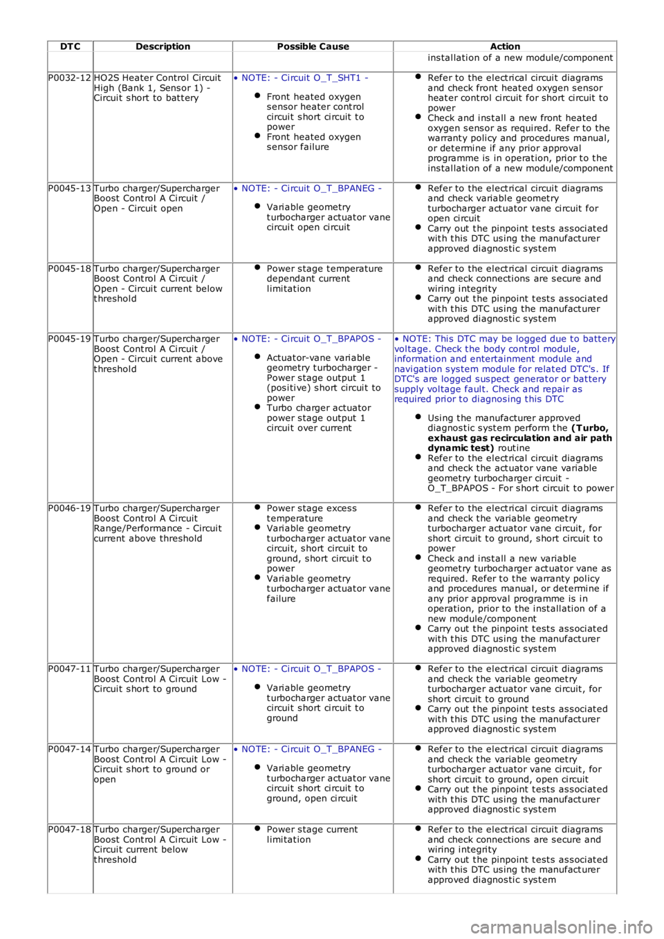
DT CDescriptionPossible CauseAction
ins tal lati on of a new modul e/component
P0032-12HO2S Heater Control CircuitHigh (Bank 1, Sens or 1) -Circui t s hort to bat t ery
• NO TE: - Ci rcuit O_T_SHT1 -
Front heated oxygens ensor heater cont rolcircui t s hort ci rcuit t opowerFront heated oxygens ensor failure
Refer to the el ect ri cal circui t diagramsand check front heat ed oxygen s ensorheat er cont rol ci rcuit for short ci rcuit t opowerCheck and i ns t all a new front heatedoxygen s ens or as requi red. Refer to thewarrant y poli cy and procedures manual,or det ermi ne if any prior approvalprogramme is in operat ion, pri or t o t heins tal lati on of a new modul e/component
P0045-13Turbo charger/SuperchargerBoost Cont rol A Ci rcuit /Open - Circui t open
• NO TE: - Ci rcuit O_T_BPANEG -
Vari able geometryt urbocharger actuat or vanecircui t open ci rcuit
Refer to the el ect ri cal circui t diagramsand check variabl e geomet ryturbocharger act uator vane ci rcuit foropen ci rcuitCarry out t he pinpoint t est s as s oci at edwit h t his DTC us ing the manufact urerapproved di agnos ti c s ys t em
P0045-18Turbo charger/SuperchargerBoost Cont rol A Ci rcuit /Open - Circui t current belowt hreshol d
Power s tage t emperaturedependant currentl imi tat ion
Refer to the el ect ri cal circui t diagramsand check connecti ons are s ecure andwiring i ntegri tyCarry out t he pinpoint t est s as s oci at edwit h t his DTC us ing the manufact urerapproved di agnos ti c s ys t em
P0045-19Turbo charger/SuperchargerBoost Cont rol A Ci rcuit /Open - Circui t current abovet hreshol d
• NO TE: - Ci rcuit O_T_BPAPOS -
Actuat or-vane vari abl egeometry t urbocharger -Power s tage output 1(pos i ti ve) s hort circui t topowerTurbo charger actuatorpower s tage output 1circui t over current
• NOTE: Thi s DTC may be logged due t o batt eryvol tage. Check t he body cont rol module,informati on and entertainment module andnavi gat ion s ys tem module for relat ed DTC's . IfDTC's are logged s us pect generat or or bat terysupply vol tage faul t. Check and repair asrequired pri or t o di agnos ing t his DTC
Usi ng t he manufacturer approveddiagnos t ic s yst em perform t he (T urbo,exhaust gas recirculation and air pathdynamic test) rout ineRefer to the el ect ri cal circui t diagramsand check t he act uat or vane variablegeomet ry turbocharger ci rcuit -O_T_BPAPOS - For s hort circuit t o power
P0046-19Turbo charger/SuperchargerBoost Cont rol A Ci rcuitRange/Performance - Circui tcurrent above threshold
Power s tage exces st emperatureVari able geometryt urbocharger actuat or vanecircui t, s hort circui t toground, s hort circuit t opowerVari able geometryt urbocharger actuat or vanefailure
Refer to the el ect ri cal circui t diagramsand check t he variable geomet ryturbocharger act uator vane ci rcuit , forshort ci rcuit t o ground, s hort circuit t opowerCheck and i ns t all a new variablegeomet ry turbocharger act uat or vane asrequired. Refer t o t he warranty pol icyand procedures manual , or det ermi ne ifany prior approval programme is i noperati on, prior to the i nst all ati on of anew module/componentCarry out t he pinpoint t est s as s oci at edwit h t his DTC us ing the manufact urerapproved di agnos ti c s ys t em
P0047-11Turbo charger/SuperchargerBoost Cont rol A Ci rcuit Low -Circui t s hort to ground
• NO TE: - Ci rcuit O_T_BPAPOS -
Vari able geometryt urbocharger actuat or vanecircui t s hort ci rcuit t oground
Refer to the el ect ri cal circui t diagramsand check t he variable geomet ryturbocharger act uator vane ci rcuit , forshort ci rcuit t o groundCarry out t he pinpoint t est s as s oci at edwit h t his DTC us ing the manufact urerapproved di agnos ti c s ys t em
P0047-14Turbo charger/SuperchargerBoost Cont rol A Ci rcuit Low -Circui t s hort to ground oropen
• NO TE: - Ci rcuit O_T_BPANEG -
Vari able geometryt urbocharger actuat or vanecircui t s hort ci rcuit t oground, open ci rcuit
Refer to the el ect ri cal circui t diagramsand check t he variable geomet ryturbocharger act uator vane ci rcuit , forshort ci rcuit t o ground, open ci rcuitCarry out t he pinpoint t est s as s oci at edwit h t his DTC us ing the manufact urerapproved di agnos ti c s ys t em
P0047-18Turbo charger/SuperchargerBoost Cont rol A Ci rcuit Low -Circui t current belowt hreshol d
Power s tage currentl imi tat ionRefer to the el ect ri cal circui t diagramsand check connecti ons are s ecure andwiring i ntegri tyCarry out t he pinpoint t est s as s oci at edwit h t his DTC us ing the manufact urerapproved di agnos ti c s ys t em
Page 93 of 3229
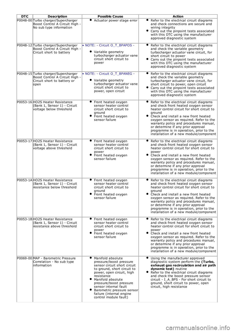
DT CDescriptionPossible CauseAction
P0048-00Turbo charger/SuperchargerBoost Cont rol A Ci rcuit High -No s ub t ype informati on
Actuat or power s tage errorRefer to the el ect ri cal circui t diagramsand check connecti ons are s ecure andwiring i ntegri tyCarry out t he pinpoint t est s as s oci at edwit h t his DTC us ing the manufact urerapproved di agnos ti c s ys t em
P0048-12Turbo charger/SuperchargerBoost Cont rol A Ci rcuit High -Circui t s hort to bat t ery
• NO TE: - Ci rcuit O_T_BPAPOS -
Vari able geometryt urbocharger actuat or vanecircui t s hort ci rcuit t opower
Refer to the el ect ri cal circui t diagramsand check t he variable geomet ryturbocharger act uator vane ci rcuit , forshort ci rcuit t o powerCarry out t he pinpoint t est s as s oci at edwit h t his DTC us ing the manufact urerapproved di agnos ti c s ys t em
P0048-15Turbo charger/SuperchargerBoost Cont rol A Ci rcuit High -Circui t s hort to bat t ery oropen
• NO TE: - Ci rcuit O_T_BPANEG -
Vari able geometryt urbocharger actuat or vanecircui t s hort ci rcuit t opower, open circui t
Refer to the el ect ri cal circui t diagramsand check t he variable geomet ryturbocharger act uator vane ci rcuit , forshort ci rcuit t o power, open circui tCarry out t he pinpoint t est s as s oci at edwit h t his DTC us ing the manufact urerapproved di agnos ti c s ys t em
P0053-16HO2S Heater Res is t ance(Bank 1, Sensor 1) - Ci rcuitvolt age bel ow t hres hol d
Front heated oxygens ensor heater cont rolcircui t s hort ci rcuit t ogroundFront heated oxygens ensor failure
Refer to the el ect ri cal circui t diagramsand check front heat ed oxygen s ensorheat er cont rol ci rcuit for short ci rcuit t ogroundCheck and i ns t all a new front heatedoxygen s ens or as requi red. Refer to thewarrant y poli cy and procedures manual,or det ermi ne if any prior approvalprogramme is in operat ion, pri or t o t heins tal lati on of a new modul e/component
P0053-17HO2S Heater Res is t ance(Bank 1, Sensor 1) - Ci rcuitvolt age above t hres hol d
Front heated oxygens ensor heater cont rolcircui t s hort ci rcuit t opowerFront heated oxygens ensor failure
Refer to the el ect ri cal circui t diagramsand check front heat ed oxygen s ensorheat er cont rol ci rcuit for short ci rcuit t opowerCheck and i ns t all a new front heatedoxygen s ens or as requi red. Refer to thewarrant y poli cy and procedures manual,or det ermi ne if any prior approvalprogramme is in operat ion, pri or t o t heins tal lati on of a new modul e/component
P0053-1AHO2S Heater Res is t ance(Bank 1, Sensor 1) - Ci rcuitres is t ance bel ow t hreshol d
Front heated oxygens ensor heater cont rolcircui t s hort ci rcuit t ogroundFront heated oxygens ensor failure
Refer to the el ect ri cal circui t diagramsand check front heat ed oxygen s ensorheat er cont rol ci rcuit for short ci rcuit t ogroundCheck and i ns t all a new front heatedoxygen s ens or as requi red. Refer to thewarrant y poli cy and procedures manual,or det ermi ne if any prior approvalprogramme is in operat ion, pri or t o t heins tal lati on of a new modul e/component
P0053-1BHO2S Heater Res is t ance(Bank 1, Sensor 1) - Ci rcuitres is t ance above t hres hol d
Front heated oxygens ensor heater cont rolcircui t s hort ci rcuit t opowerFront heated oxygens ensor failure
Refer to the el ect ri cal circui t diagramsand check front heat ed oxygen s ensorheat er cont rol ci rcuit for short ci rcuit t opowerCheck and i ns t all a new front heatedoxygen s ens or as requi red. Refer to thewarrant y poli cy and procedures manual,or det ermi ne if any prior approvalprogramme is in operat ion, pri or t o t heins tal lati on of a new modul e/component
P0069-00MAP - Barometric Pres s ureCorrelati on - No s ub t ypeinformat ion
Manifold abs olut epres s ure/boos t pres s ures ensor circui t s hort ci rcuitt o ground, s hort ci rcuit t opower, open circui t, highresi st anceManifold abs olut epres s ure/boos t pres s ures ensor i nt ernal faul tBaromet ri c pres s ure s ens orfailure (internal enginecontrol modul e fault )
Usi ng t he manufacturer approveddiagnos t ic s yst em perform t he (T urbo,exhaust gas recirculation and air pathdynamic test) rout ineRefer to the el ect ri cal circui t diagramsand check t he boos t pres s ure s ens orci rcuit - I_A_BPS - For s hort circui t toground, s hort circui t t o power, openci rcuit , high resi st ance
Page 96 of 3229
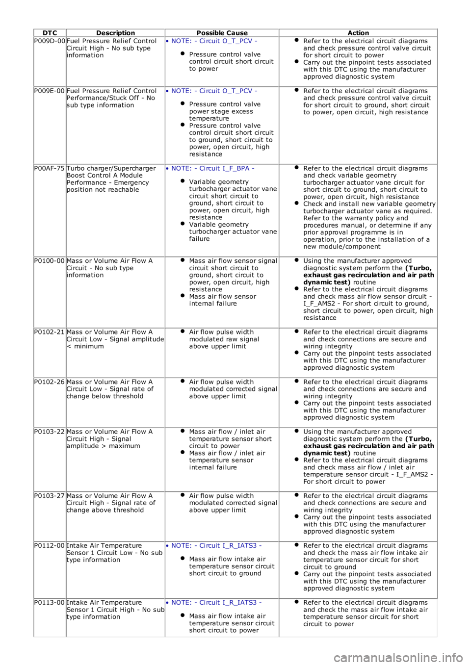
DT CDescriptionPossible CauseAction
P009D-00Fuel Pres s ure Rel ief ControlCircui t High - No s ub typeinformat ion
• NO TE: - Ci rcuit O_T_PCV -
Pres s ure control val vecontrol circui t s hort circuitt o power
Refer to the el ect ri cal circui t diagramsand check pres s ure control valve ci rcuitfor s hort circui t to powerCarry out t he pinpoint t est s as s oci at edwit h t his DTC us ing the manufact urerapproved di agnos ti c s ys t em
P009E-00Fuel Pres s ure Rel ief ControlPerformance/Stuck Off - Nos ub type i nformati on
• NO TE: - Ci rcuit O_T_PCV -
Pres s ure control val vepower s tage exces st emperaturePres s ure control val vecontrol circui t s hort circuitt o ground, s hort ci rcuit t opower, open circui t, highresi st ance
Refer to the el ect ri cal circui t diagramsand check pres s ure control valve ci rcuitfor s hort circui t to ground, s hort circui tto power, open ci rcuit , hi gh res i st ance
P00AF-75Turbo charger/SuperchargerBoost Cont rol A ModulePerformance - Emergencyposi ti on not reachable
• NO TE: - Ci rcuit I_F_BPA -
Vari able geometryt urbocharger actuat or vanecircui t s hort ci rcuit t oground, s hort circuit t opower, open circui t, highresi st anceVari able geometryt urbocharger actuat or vanefailure
Refer to the el ect ri cal circui t diagramsand check variabl e geomet ryturbocharger act uator vane ci rcuit forshort ci rcuit t o ground, s hort circuit t opower, open ci rcuit , high res i st anceCheck and i ns t all new vari abl e geometryturbocharger act uator vane as required.Refer to the warrant y policy andprocedures manual , or det ermi ne if anyprior approval programme is i noperati on, prior to the i nst all ati on of anew module/component
P0100-00Mas s or Vol ume Ai r Fl ow ACircui t - No s ub t ypeinformat ion
Mas s air flow sens or si gnalcircui t s hort ci rcuit t oground, s hort circuit t opower, open circui t, highresi st anceMas s air flow sens ori nt ernal fai lure
Usi ng t he manufacturer approveddiagnos t ic s yst em perform t he (T urbo,exhaust gas recirculation and air pathdynamic test) rout ineRefer to the el ect ri cal circui t diagramsand check mas s air flow sens or ci rcuit -I_F_AMS2 - For short ci rcuit t o ground,short ci rcuit t o power, open circui t, highres is t ance
P0102-21Mas s or Vol ume Ai r Fl ow ACircui t Low - Signal amplit ude< minimum
Ai r flow puls e wi dt hmodulat ed raw s ignalabove upper l imi t
Refer to the el ect ri cal circui t diagramsand check connecti ons are s ecure andwiring i ntegri tyCarry out t he pinpoint t est s as s oci at edwit h t his DTC us ing the manufact urerapproved di agnos ti c s ys t em
P0102-26Mas s or Vol ume Ai r Fl ow ACircui t Low - Signal rat e ofchange below threshold
Ai r flow puls e wi dt hmodulat ed correct ed si gnalabove upper l imi t
Refer to the el ect ri cal circui t diagramsand check connecti ons are s ecure andwiring i ntegri tyCarry out t he pinpoint t est s as s oci at edwit h t his DTC us ing the manufact urerapproved di agnos ti c s ys t em
P0103-22Mas s or Vol ume Ai r Fl ow ACircui t High - Si gnalampli tude > maximum
Mas s air flow / inlet ai rt emperature s ensor s hortcircui t to powerMas s air flow / inlet ai rt emperature s ensori nt ernal fai lure
Usi ng t he manufacturer approveddiagnos t ic s yst em perform t he (T urbo,exhaust gas recirculation and air pathdynamic test) rout ineRefer to the el ect ri cal circui t diagramsand check mas s air flow / inlet ai rtemperat ure sens or ci rcuit - I_F_AMS2 -For s hort circui t to power
P0103-27Mas s or Vol ume Ai r Fl ow ACircui t High - Si gnal rat e ofchange above threshold
Ai r flow puls e wi dt hmodulat ed correct ed si gnalabove upper l imi t
Refer to the el ect ri cal circui t diagramsand check connecti ons are s ecure andwiring i ntegri tyCarry out t he pinpoint t est s as s oci at edwit h t his DTC us ing the manufact urerapproved di agnos ti c s ys t em
P0112-00Int ake Air Temperat ureSens or 1 Ci rcuit Low - No s ubt ype i nformati on
• NO TE: - Ci rcuit I_R_IATS3 -
Mas s air flow int ake ai rt emperature s ensor circui ts hort circui t to ground
Refer to the el ect ri cal circui t diagramsand check t he mas s air flow i ntake airtemperat ure sens or ci rcuit for shortci rcuit t o groundCarry out t he pinpoint t est s as s oci at edwit h t his DTC us ing the manufact urerapproved di agnos ti c s ys t em
P0113-00Int ake Air Temperat ureSens or 1 Ci rcuit Hi gh - No s ubt ype i nformati on
• NO TE: - Ci rcuit I_R_IATS3 -
Mas s air flow int ake ai rt emperature s ensor circui ts hort circui t to power
Refer to the el ect ri cal circui t diagramsand check t he mas s air flow i ntake airtemperat ure sens or ci rcuit for shortci rcuit t o power
Page 1844 of 3229
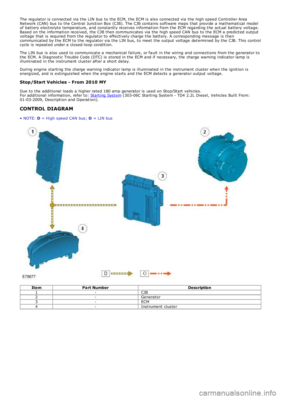
The regulat or is connect ed vi a t he LIN bus to the ECM, t he ECM i s als o connect ed vi a t he high s peed Control ler AreaNetwork (CAN) bus t o t he Central Junct ion Box (CJB). The CJB cont ains s oft ware maps t hat provi de a mat hemati cal modelof bat t ery elect rolyt e t emperature, and const antl y receives informat ion from t he ECM regardi ng t he act ual bat tery vol tage.Based on the informati on received, the CJB t hen communi cat es via the hi gh speed CAN bus to t he ECM a predict ed out putvolt age that is required from t he regulat or to effecti vel y charge t he batt ery. A corresponding mes s age is t hencommunicated by t he ECM t o t he regul at or via t he LIN bus, t o meet t he output volt age det ermi ned by the CJB. This controlcycle is repeat ed under a cl osed-loop condi ti on.
The LIN bus is al so used t o communicat e a mechani cal failure, or fault i n the wiring and connecti ons from t he generator t ot he ECM. A Diagnost ic Troubl e Code (DTC) is s t ored in the ECM and if neces s ary, t he charge warning indicator lamp isil lumi nat ed i n the ins trument cl us t er aft er a short del ay.
Duri ng engi ne s tarti ng the charge warning i ndi cat or lamp is i ll uminated i n t he ins t rument clus ter when t he ignit ion i senergized, and is exti ngui s hed when the engine s t art s and t he ECM detects a generator output volt age.
Stop/Start Vehicles - From 2010 MY
Due t o t he addi ti onal l oads a hi gher rated 180 amp generator is us ed on St op/St art vehi cles .For addit ional informat ion, refer t o: Starti ng Sys t em (303-06C Starti ng Syst em - TD4 2.2L Di es el, Vehicles Bui lt From:01-03-2009, Descripti on and Operat ion).
CONTROL DIAGRAM
• NOTE: D = Hi gh s peed CAN bus ; O = LIN bus
ItemPart NumberDescription
1-CJB2-Generator
3-ECM
4-Ins t rument clus ter
Page 1865 of 3229
1
1
1
1
1
1
1
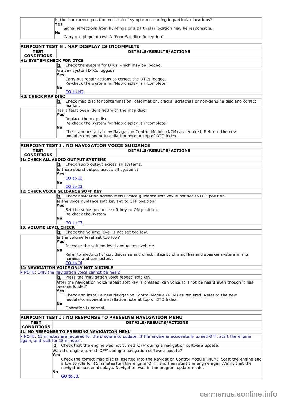
Is t he 'car current posi ti on not st able' sympt om occurri ng in part icul ar locat ions ?YesSi gnal reflecti ons from buil dings or a part icular locati on may be respons ible.NoCarry out pinpoint t est A "Poor Satell it e Recept ion"
PINPOINT TEST H : MAP DISPLAY IS INCOMPLETE
T ESTCONDIT IONSDET AILS/R ESULT S/ACT IONS
H1: SYST EM CHECK FOR DT CSCheck t he sys t em for DTCs whi ch may be l ogged.
Are any s yst em DTCs l ogged?YesCarry out repai r act ions t o correct t he DTCs logged.Re-check t he s ys t em for 'Map dis play i s i ncomplet e'.NoGO t o H2.H2: CHECK MAP DISC
Check map di sc for cont aminat ion, deformat ion, cracks , s cratches or non-genui ne dis c and correctmarket.Has a fault been i dent ified wi th the map dis c?YesReplace t he map di sc.Re-check t he s ys t em for 'Map dis play i s i ncomplet e'.NoCheck and ins t al l a new Navigat ion Control Modul e (NCM) as required. Refer t o t he newmodul e/component ins t al lat ion not e at top of DTC Index.
PINPOINT TEST I : NO NAVIGATION VOICE GUIDANCE
T ESTCONDIT IONSDET AILS/R ESULT S/ACT IONS
I1: CHECK ALL AUDIO OUT PUT SYST EMSCheck audi o output acros s all s yst ems .
Is t here s ound output across all s ys t ems ?YesGO t o I2.NoGO t o I3.
I2: CHECK VOICE GUIDANCE SO FT KEYCheck navi gat ion screen menu, voice guidance s oft key is not s et t o OFF posi ti on.
Is t he voice guidance soft key set t o OFF pos it ion?YesSet t he voice guidance soft key to O N posi ti on.Re-check t he s ys t emNoGO t o I3.I3: VOLUME LEVEL CHECK
Check t he vol ume l evel is not s et t oo low.
Is t he volume l evel s et too low?YesIncrease the vol ume level and re-tes t vehi cl e.NoRefer to el ect ri cal circui t diagrams and check int egrit y of ampli fier and s peaker s yst em wiringharnes s and connect ors .GO t o I4.
I4: NAVIGAT ION VOICE ONLY NOT AUDIBLE• NOTE: Onl y the navigat ion voice cannot be heard.
Press the 'Navi gat ion voi ce repeat ' s oft key.
After t he navi gat ion voi ce repeat soft key is pres s ed, can voice s t il l not be heard even t hough it hasbecome l ouder?YesCheck and ins t al l a new Navigat ion Control Modul e (NCM) as required. Refer t o t he newmodul e/component ins t al lat ion not e at top of DTC Index.NoO perati on is normal.
PINPOINT TEST J : NO RESPONSE TO PRESSING NAVIGATION MENU
T ESTCONDIT IONSDET AILS/RESULT S/ACT IONS
J1: NO RESPONSE T O PRESSING NAVIGAT ION MENU
• NOTE: 15 minutes are required for t he program t o update. If the engine i s acci dentally turned OFF, s tart the engi neagain, and wait for 15 minut es.
Check t hat t he engine was not t urned 'O FF' during a navi gat ion software updat e.
W as t he engi ne turned 'OFF' during a navigat ion s oft ware updat e?YesCheck t he correct map di sc is i ns erted i nto t he Navigati on Control Module (NCM). Start the engine andal low to idle for 15 mi nut es Turn t he engi ne 'OFF', and t hen s tart the engine again.Verify t hat t henavigat ion s creen dis plays . Navi gat ion was in the program update mode.NoGO t o J3.
Page 1962 of 3229
Publi s hed: 11-May-2011
Module Communications Network - Communications Network
Des cript ion and Operat ion
OVERVIEW
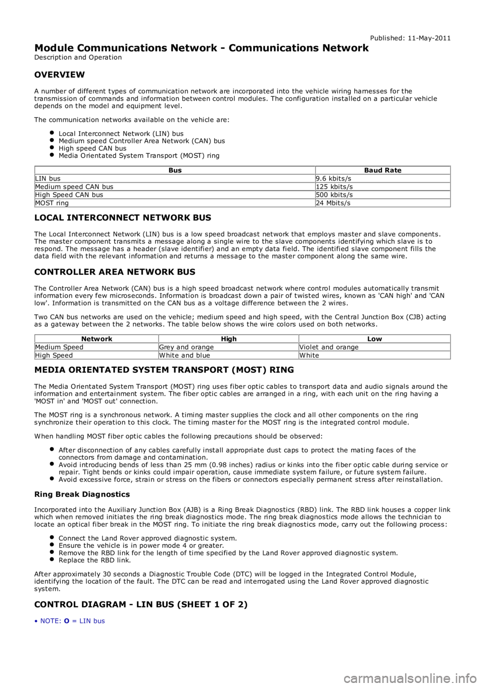
A number of different t ypes of communicati on network are incorporated into the vehicle wiring harnes s es for t het ransmis s ion of commands and informat ion between control modul es. The confi gurati on ins tal led on a parti cul ar vehicl edepends on t he model and equi pment level .
The communicati on net works avail abl e on t he vehi cl e are:
Local Int erconnect Network (LIN) busMedium speed Controll er Area Network (CAN) busHigh speed CAN busMedia O rient ated Sys tem Trans port (MO ST) ring
BusBaud Rate
LIN bus9.6 kbit s /s
Medium s peed CAN bus125 kbi ts /sHi gh Speed CAN bus500 kbi ts /s
MOST ring24 Mbit s/s
LOCAL INTERCONNECT NETWORK BUS
The Local Int erconnect Network (LIN) bus is a low s peed broadcas t net work that employs mas ter and s lave component s .The mas ter component t rans mit s a mess age along a si ngle wi re to the s lave component s i dent ifyi ng which s lave i s t ores pond. The mes s age has a header (s lave ident ifi er) and an empt y data fi eld. The identi fi ed s lave component fi ll s thedata fiel d wi th t he relevant i nformat ion and ret urns a mes s age to the mast er component along t he s ame wire.
CONTROLLER AREA NETWORK BUS
The Control ler Area Network (CAN) bus i s a high speed broadcast net work where cont rol modules aut omat icall y t rans mitinformat ion every few micros econds . Informati on is broadcas t down a pair of t wis t ed wires, known as 'CAN high' and 'CANlow'. Informat ion i s transmit ted on t he CAN bus as a vol tage di fference bet ween t he 2 wi res .
Two CAN bus net works are used on the vehicle; medi um s peed and high s peed, wi th the Cent ral Juncti on Box (CJB) acti ngas a gat eway bet ween t he 2 networks . The t abl e below shows t he wi re colors us ed on both net works .
Netw orkHighLow
Medium SpeedGrey and orangeViol et and orange
Hi gh SpeedW hit e and bl ueW hi te
MEDIA ORIENTATED SYSTEM TRANSPORT (MOST) RING
The Media O rient ated Sys tem Trans port (MO ST) ring us es fiber opt ic cables t o t rans port data and audio s ignal s around t heinformat ion and ent ertai nment sys tem. The fiber opti c cabl es are arranged in a ri ng, wit h each uni t on t he ri ng havi ng a'MOST in' and 'MOST out ' connect ion.
The MOST ring i s a s ynchronous net work. A t imi ng mas ter s uppl ies t he clock and all ot her component s on t he ri ngs ynchronize t heir operat ion t o t hi s clock. The t iming mas t er for the MOST ri ng is the i ntegrat ed cont rol module.
W hen handli ng MOST fiber opt ic cables t he fol lowi ng precaut ions s houl d be obs erved:
Aft er dis connect ion of any cables careful ly i nst all appropri ate dus t caps to protect the mati ng faces of theconnectors from damage and contami nat ion.Avoi d i nt roducing bends of les s t han 25 mm (0.98 inches ) radi us or ki nks int o the fiber opti c cabl e duri ng s ervice orrepair. Tight bends or kinks could i mpair operat ion, caus e immediate s ys t em failure, or future s ys t em fail ure.Avoi d exces s ive force, st rai n or s tress on the fibers or connect ors es peci ally permanent st res s after rei nst all at ion.
Ring Break Diag nostics
Incorporat ed i nt o t he Auxili ary Junct ion Box (AJB) is a Ri ng Break Di agnos ti cs (RBD) l ink. The RBD li nk hous es a copper linkwhich when removed init iat es the ri ng break diagnost ics mode. The ri ng break di agnosti cs mode allows the t echni ci an tolocate an opt ical fi ber break in t he MOST ring. To i nit iate the ring break diagnos t ics mode, carry out t he fol lowi ng proces s :
Connect t he Land Rover approved di agnos ti c s yst em.Ensure t he vehi cl e is in power mode 4 or great er.Remove the RBD li nk for t he length of ti me s peci fi ed by the Land Rover approved di agnos ti c s ys t em.Replace the RBD li nk.
Aft er approxi matel y 30 s econds a Di agnos t ic Trouble Code (DTC) wi ll be logged i n the Int egrated Cont rol Modul e,identi fyi ng the l ocat ion of t he faul t. The DTC can be read and int errogat ed usi ng t he Land Rover approved di agnos ti cs ys t em.
CONTROL DIAGRAM - LIN BUS (SHEET 1 OF 2)
• NOTE: O = LIN bus
Page 2233 of 3229
pri nted on t he i nner s urface of t he rear s creen.
Operat ion of t he window l ift s ys t em i s cont rol led by t he CJB in conjuncti on wit h t he dri ver door module and t he frontpass enger door module. The door modul es are mount ed on t he regulat ors of t hei r res pect ive front windows . Door modul esare al s o mounted on bot h rear wi ndow regulat ors , and communicat e wi th the front door modules over t he LocalInt erconnect Network (LIN) bus .
The window lift s ys t em features one shot up and down operat ion, plus an ant i-trap feat ure for al l door wi ndows .
If the bat tery is di sconnect ed, t he wi ndow lift s yst em will requi re cali brat ing on bat tery re-connect ion. To cali brate thes ys t em t he fol lowi ng rout ine mus t be carried out .
W i th the i gnit ion on:
Fully cl ose the door glas s and rel eas e t he s wit ch.Re-apply t he s wit ch t o clos e t he door glas s and hold for approximat ely 2 seconds .Fully open t he door glas s and rel eas e t he s wit ch.Re-apply t he s wit ch t o open the door glas s and hold for approxi mat el y 2 s econds .Repeat for al l remai ni ng wi ndows .
DOOR MODULES
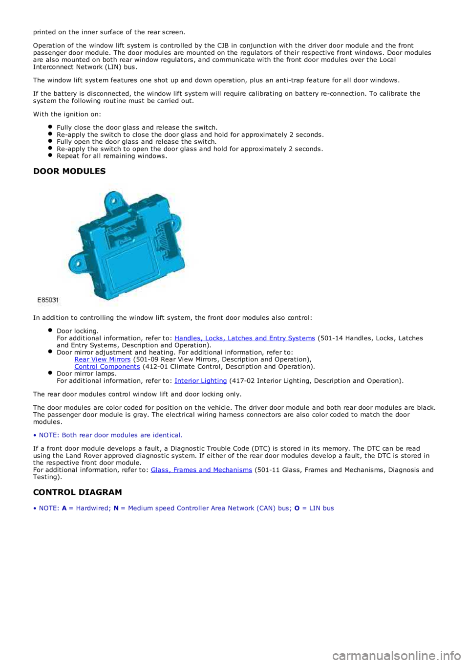
In addi ti on t o cont rol ling the wi ndow li ft s ys tem, t he front door modules al so cont rol:
Door locki ng.For addit ional informat ion, refer t o: Handl es, Locks , Latches and Entry Sys t ems (501-14 Handl es, Locks , Latchesand Entry Syst ems , Descri pti on and Operat ion).Door mirror adjus tment and heat ing. For addit ional informati on, refer t o:Rear Vi ew Mi rrors (501-09 Rear Vi ew Mi rrors , Descripti on and Operat ion),Cont rol Component s (412-01 Cli mate Cont rol , Des cri pti on and Operati on).Door mirror l amps .For addit ional informat ion, refer t o: Int eri or Li ght ing (417-02 Interior Lighti ng, Des cri pt ion and Operati on).
The rear door modul es cont rol wi ndow lift and door locki ng onl y.
The door modul es are color coded for posi ti on on t he vehi cl e. The driver door modul e and both rear door modules are black.The pass enger door module i s gray. The electrical wiring harnes s connectors are al s o col or coded t o mat ch the doormodules .
• NOTE: Both rear door modul es are i dent ical.
If a front door module develops a fault , a Diagnos ti c Trouble Code (DTC) is s t ored in it s memory. The DTC can be readus ing t he Land Rover approved diagnos t ic s yst em. If eit her of t he rear door modul es develop a fault , t he DTC is st ored int he res pect ive front door modul e.For addit ional informat ion, refer t o: Glas s , Frames and Mechani sms (501-11 Glas s, Frames and Mechanis ms , Diagnos is andTest ing).
CONTROL DIAGRAM
• NOTE: A = Hardwi red; N = Medium s peed Cont roll er Area Net work (CAN) bus ; O = LIN bus
Page 3099 of 3229
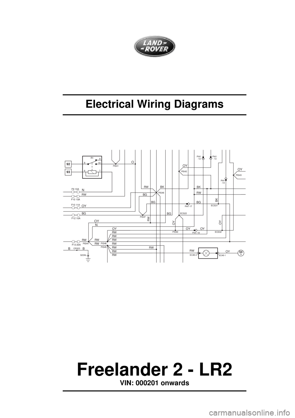
Electrical Wiring Diagrams
Freelander 2 - LR2
VIN: 000201 onwards
PIS40ECS31
BG
PI41-18OY OY
PI41-17
PI41
-14
ECS32
BG
PIS47
BG
BG
OY
PIS48
PIS46
RW
RW
RW
RW
RW
RW
RW
RWPIS45PIS44RW
RW RW
92
93
F9 10A
F10 10A
F12 10A
F13 20A
8
610
7R19
OY
OYOY
N NO
RW
RW RW
RW
OY
BG
OY
OYEC49-2
EC49-1
BK
S54
PI41
-12
B
G23AL
CRS23B
PIS41
PI41
-13
BK
PIS42PIS43
RW
BK
ECS22
OY
F10 11A