2006 LAND ROVER FRELANDER 2 seat adjustment
[x] Cancel search: seat adjustmentPage 2186 of 3229
Memory recall is al s o immedi atel y cancelled if t he vehi cl e is driven from t he st ati o nary pos it ion before t he seat has
reached the reques t ed memory pos i ti on.
Proport ional Mode
If the vehicle is already in moti on when the swi tch pack memory posi ti on butt on is p ress ed, the memory recal l functi on wil l
operate in 'proport ional' mode. Proport ional mode recal ls the s eat (and ext erior mi r ror) pos it ion for the durat ion t hat the
memory s wit ch is held in the pres s ed s tat e. W hen t he memory pos i ti on but t on is relea s ed the memory recal l wil l
immediatel y s top, unles s the seat has already reached t he int ended memory pos it ion.
In order to reach t he int ended s t ored memory posi ti on whil e t he vehi cl e is moving, t he memory pos it ion but ton mus t not
be rel eased unt il all s eat, and exterior mi rror movement s are compl et e.
Immediate seat adjustment function
The immediate adjust ment functi on is act ivated when a s wit ch pack s eat posi ti on s wit ch (recl ine, s lide or height ) is
operated.
Pres s ing any of t he seat adjus t ment swi tches wil l init iat e t he corres pondi ng direct i on mot or to move t he seat i n t hat
direct ion, unti l t he s wit ch is releas ed. Onl y 2 s eat mot ors wi ll operate at any one ti me.
Automatic Monitoring Functions
The power seat module aut omati c monit ori ng functi ons are detai led as follows :
Stal l det ect ion mode Sleep mode
Batt ery moni tor mode.
Stall detection mode
A s eat mot or i s deemed t o have st all ed if t here i s no change i n t he input t hat i s re ceived from the corres ponding feedback
s ens or for 200 mill is econds , while that axis i s being driven.
If a s tall condit ion i s det ected by t he power seat module then t he dri ve to that axi s i s cancell ed for t he remai nder of t hat
memory operati on (memory recal l), or unt il t he s wit ch is re-s elected (immediate s eat adjus t ment).
For al l seat mot or manual movements during an immedi at e s eat adjus tment funct ion, wh en a mot or is driven and a s t al l
occurs the power s eat modul e records and s t ores t he s tal l pos it ion (s oft s t op) t hat the s t all occurred. If movement occurs
beyond t he s tored s oft s top st all pos it ion, then t he s tal l pos it ion i s eras ed from t he power s eat modul e memory. Thi s wil l
always all ow movement past a previousl y recorded s t all posi ti on once movement has be en regi st ered beyond that pos it ion
(i.e. by press ing the s wi tch for longer t han 2 s econds ).
If the mot or movement has s t opped due t o a motor s tal l (s eat obs t ructi on for example ), once t he obst ruct ion i s cl eared
t hen that axi s may be act ivated again to move pas t t he new s oft s t op s tal l pos it ion by re-s elect ing t he appropriat e s wit ch
and pres s ing for longer t han 2 s econds . If t he s wit ch is not operat ed to move t he se at pas t the new soft s top pos it ion,
t hi s posi ti on wi ll remai n s tored in the power s eat modul e memory as t he full axis mo vement .
If motor movement has st opped due to los s of sens or feedback (s ens or or wiring failu re) then t hat axi s may be acti vat ed
agai n t o move pas t the st all posi ti on by re-s electi ng the appropriate s wit ch and pre s si ng for l onger t han 2 s econds. This
all ows cont rol of the motor t o be mai nt ained i f sens or feedback i s los t .
Upon re-s el ect ion of movement , if s ens or puls es are det ect ed t hen the mot or wil l con t inue t o be dri ven unt il t he s wit ch is
rel eas ed or another s tall condit ion i s det ected. If s ens or feedback is not det ect ed then t he mot or is only driven for 0.5
s econd and t hen s tops , unt il t he s wit ch is releas ed and then pres s ed again for longe r t han 2 s econds , when a furt her 0.5
s econd of acti vat ion i s permi tt ed and s o on. This i s known as 'i nch mode'.
If there is a fail ure wit h the medium speed CAN bus net work, the seat wi ll operate i n 'inch mode'.
• NOTE: For di agnos t ic purpos es, an i ndicat ion of medi um s peed CAN bus dis connecti on is apparent i f the s eat is operat ing
in 'inch mode' and eit her t he s eat cont rol module, CJB or door cont rol modules are n ot s hown connect ed t o t he medium
s peed CAN bus.
Sleep mode
The power seat module features a s leep mode t o reduce power cons umpt ion t o t he requi red mi ni mum.
If the power s eat modul e is bei ng prevent ed from ent eri ng s leep mode due t o mot or mo vement , memory recall or s wit ch
pack operat ion, t hen the modul e wil l ent er s leep mode when t he current funct ion has t ermi nat ed.
• NOTE: In t he cas e of a memory recal l, all memory recall operat ions are carri ed out before t he power seat module ent ers
s leep mode, and not jus t the current motor movement.
The power seat module will exit s l eep mode when any CAN bus acti vi ty is det ect ed.
Battery monitor mode
The power seat module moni tors t he input power s upply t o make s ure there is suffi ci e nt bat tery vol tage avail abl e for
engi ne cranking. If t he batt ery volt age drops below 10.5 volt s , then t he power seat module ignores all reques ts for a
memory recall unti l the bat tery vol tage i s great er t han 11.0 vol ts .
If the bat tery vol tage drops bel ow 8.5 vol ts , t hen the power s eat modul e ignores al l reques t s for s eat movement unt il t he
batt ery volt age is greater t han 9.0 volt s .
If the bat tery vol tage i s great er t han 16.5 volt s , then t he power seat module ignore s all reques t s for s eat movement unt il
t he bat t ery volt age drops below 16.0 volt s.
Page 2221 of 3229
Publi s hed: 11-May-2011
Seating - Front Seat Height Adjustment Motor
Removal and Inst all ati on
Removal
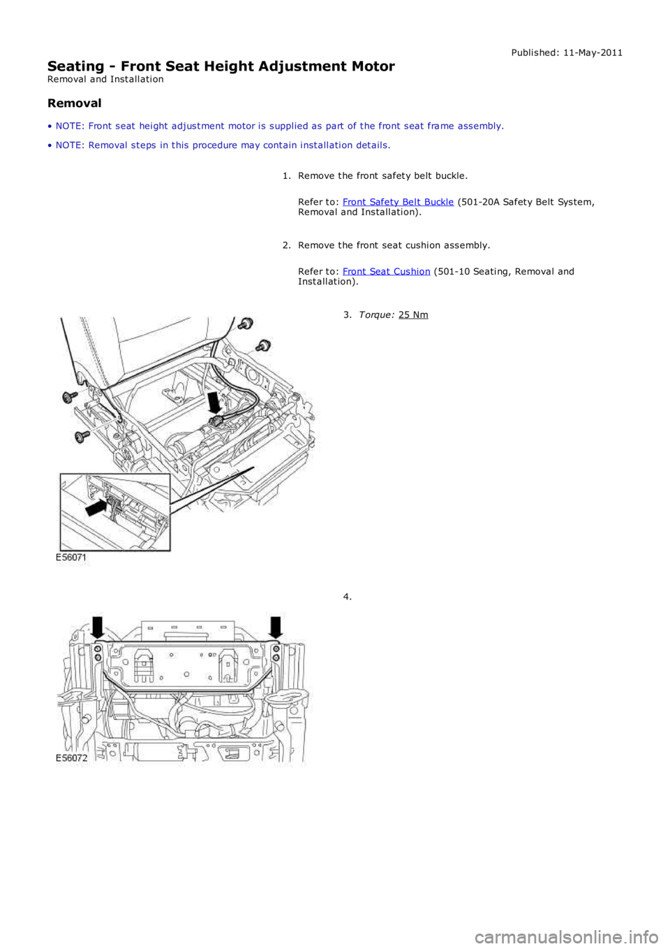
• NOTE: Front s eat hei ght adjus t ment motor i s s uppl ied as part of t he front s eat fra me ass embly.
• NOTE: Removal s t eps in t his procedure may cont ain i nst all ati on det ail s.
Remove t he front safet y belt buckle.
Refer t o: Front Safety Bel t Buckle (501-20A Safet y Belt Sys tem,
Removal and Ins tall ati on).
1.
Remove t he front seat cushi on ass embly.
Refer t o: Front Seat Cus hion (501-10 Seati ng, Removal and
Inst all at ion).
2. T orque:
25 Nm 3.
4.
Page 2223 of 3229
Publi shed: 11-May-2011
Seating - Front Seat Manual Height Adjustment LeverRemoval and Installation
Removal
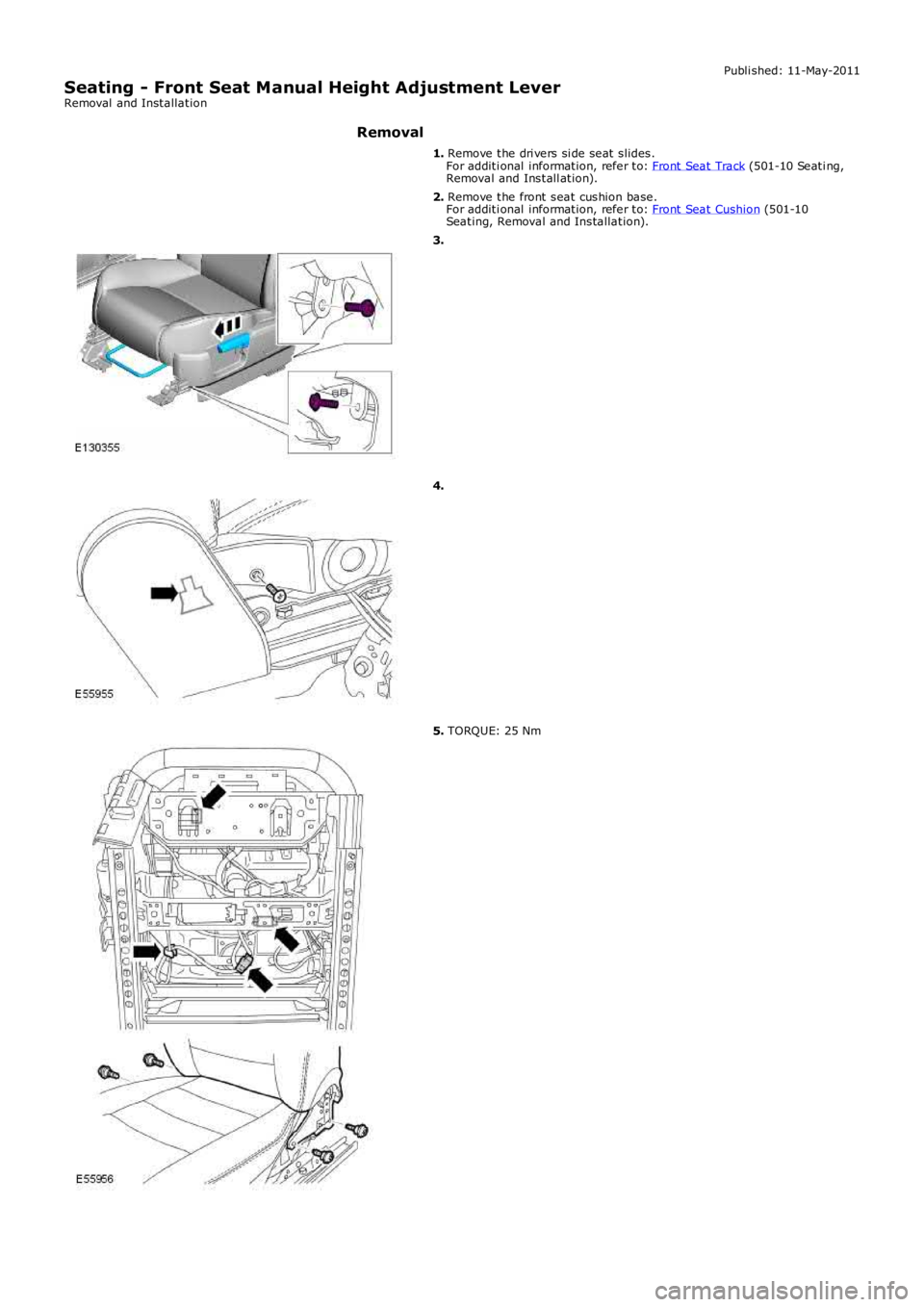
1. Remove the dri vers si de seat slides.For additi onal information, refer to: Front Seat Track (501-10 Seati ng,Removal and Install ation).
2. Remove the front seat cushion base.For additi onal information, refer to: Front Seat Cushion (501-10Seating, Removal and Installation).
3.
4.
5. TORQUE: 25 Nm
Page 2723 of 3229

Contents
3
R
Quick start
QUICK START ................................................... 7
Filling station information
FILLING STATION INFORMATION................... 33
Introduction
SYMBOLS GLOSSARY .................................... 35
LABEL LOCATIONS ......................................... 35
HEALTH AND SAFETY ..................................... 36
DATA RECORDING.......................................... 37
DISABILITY MODIFICATIONS ......................... 37
PARTS AND ACCESSORIES ............................ 37
Keys and remote controls
USING THE KEY .............................................. 40
GENERAL INFORMATION ON RADIO
FREQUENCIES ................................................ 40
USING THE REMOTE CONTROL ..................... 41
Locks
LOCKING AND UNLOCKING ............................ 44
Alarm
ARMING THE ALARM ..................................... 45
DISARMING THE ALARM ............................... 46
Seats
SITTING IN THE CORRECT POSITION ............ 47
MANUAL SEATS ............................................. 48
ELECTRIC SEATS ............................................ 49
HEAD RESTRAINTS ........................................ 51
REAR SEATS................................................... 51
HEATED SEATS............................................... 53
Seat belts
PRINCIPLE OF OPERATION ............................ 54
SEAT BELT REMINDER ................................... 55
FASTENING THE SEAT BELTS ........................ 56
SEAT BELT HEIGHT ADJUSTMENT................. 56
USING SEAT BELTS DURI NG PREGNANCY .... 57
Supplementary restraints system
PRINCIPLE OF OPERATION ............................ 58
AIRBAG WARNING LAMP ............................... 61
DISABLING THE PASSENGER AIRBAG ........... 62
AIRBAG SERVICE INFORMATION ................... 63
Child safety
CHILD SEATS ................................................. 64
BOOSTER CUSHIONS ..................................... 66
ISOFIX ANCHOR POINTS................................ 67
CHILD SAFETY LOCKS ................................... 69
Steering wheel
ADJUSTING THE STEERING WHEEL .............. 70
AUDIO CONTROL ........................................... 70
Lighting
LIGHTING CONTROL ...................................... 72
FRONT FOG LAMPS........................................ 72
REAR FOG LAMPS.......................................... 73
ADJUSTING THE HEADLAMPS....................... 73
HEADLAMP LEVELLING ................................. 73
HAZARD WARNING FLASHERS...................... 74
ADAPTIVE FRONT LIGHTING SYSTEM (AFS) . 74
DIRECTION INDICATORS ............................... 75
INTERIOR LAMPS .......................................... 76
APPROACH LAMPS ........................................ 76
CHANGING A BULB ........................................ 77
BULB SPECIFICATION CHART ........................ 86
Wipers and washers
WINDSCREEN WIPERS .................................. 87
RAIN SENSOR ................................................ 87
WINDSCREEN WASHERS............................... 88
HEADLAMP WASHERS................................... 88
REAR WINDOW WIPER AND WASHERS ........ 89
ADJUSTING THE WINDSCREEN WASHER JETS .
89
CHECKING THE WIPER BLADES .................... 90
CHANGING THE WIPER BLADES.................... 90
Windows and mirrors
ELECTRIC WINDOWS ..................................... 93
EXTERIOR MIRRORS ..................................... 94
ELECTRIC EXTERIOR MIRRORS .................... 95
INTERIOR MIRROR ........................................ 96
Instruments
INSTRUMENT PANEL OVERVIEW .................. 97
Information displays
TRIP COMPUTER ........................................... 99
INFORMATION MESSAGES ............................ 99
Page 2730 of 3229
10
Quick start
L
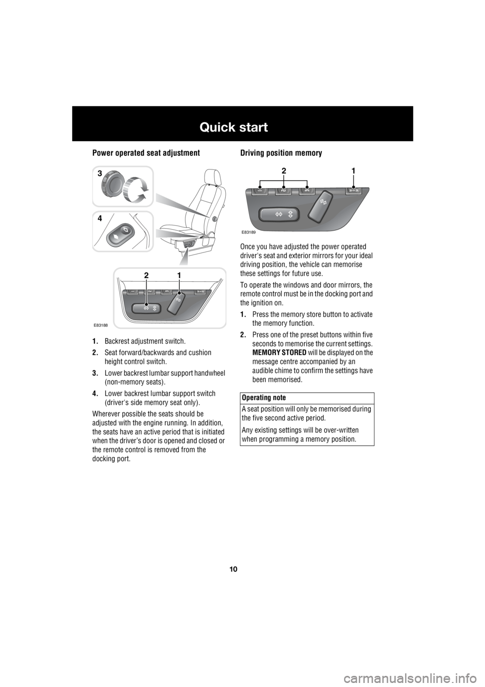
Power operated seat adjustment
1. Backrest adjustment switch.
2. Seat forward/backwards and cushion
height control switch.
3. Lower backrest lumbar support handwheel
(non-memory seats).
4. Lower backrest lumbar support switch
(driver's side memory seat only).
Wherever possible the seats should be
adjusted with the engine running. In addition,
the seats have an active period that is initiated
when the driver’s door is opened and closed or
the remote control is removed from the
docking port.
Driving position memory
Once you have adjusted the power operated
driver's seat and exterior mirrors for your ideal
driving position, the vehicle can memorise
these settings for future use.
To operate the windows and door mirrors, the
remote control must be in the docking port and
the ignition on.
1. Press the memory store button to activate
the memory function.
2. Press one of the preset buttons within five
seconds to memorise the current settings.
MEMORY STORED will be displayed on the
message centre accompanied by an
audible chime to confirm the settings have
been memorised.
E83188
12
3
4
Operating note
A seat position will onl y be memorised during
the five second active period.
Any existing settings w ill be over-written
when programming a memory position.
E83189
12
Page 2731 of 3229
11
Quick start
R
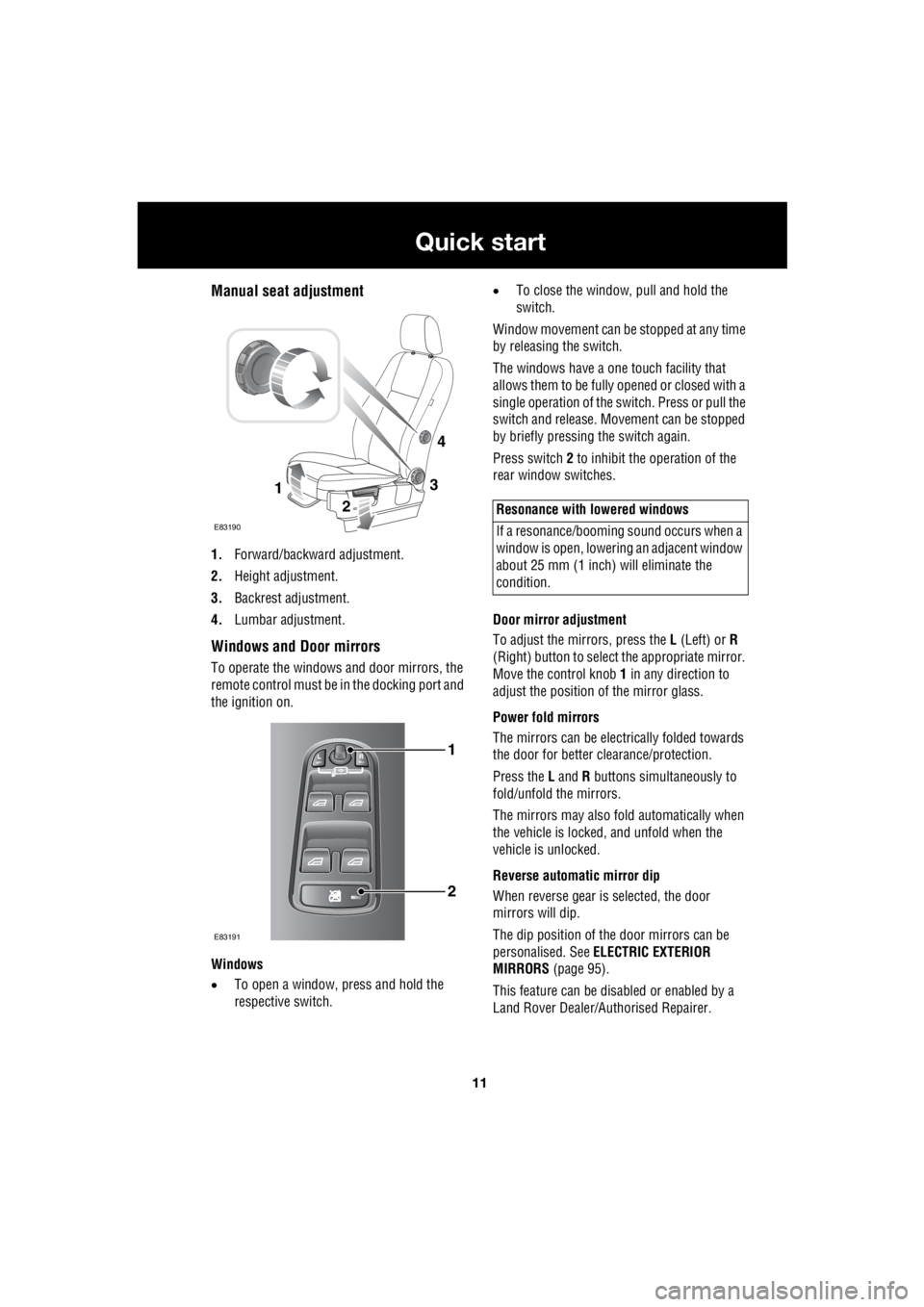
Manual seat adjustment
1. Forward/backward adjustment.
2. Height adjustment.
3. Backrest adjustment.
4. Lumbar adjustment.
Windows and Door mirrors
To operate the windows and door mirrors, the
remote control must be in the docking port and
the ignition on.
Windows
• To open a window, press and hold the
respective switch. •
To close the window, pull and hold the
switch.
Window movement can be stopped at any time
by releasing the switch.
The windows have a one touch facility that
allows them to be fully opened or closed with a
single operation of the switch. Press or pull the
switch and release. Mo vement can be stopped
by briefly pressing the switch again.
Press switch 2 to inhibit the operation of the
rear window switches.
Door mirror adjustment
To adjust the mirrors, press the L (Left) or R
(Right) button to select the appropriate mirror.
Move the control knob 1 in any direction to
adjust the position of the mirror glass.
Power fold mirrors
The mirrors can be electr ically folded towards
the door for better clearance/protection.
Press the L and R buttons simultaneously to
fold/unfold the mirrors.
The mirrors may also fold automatically when
the vehicle is locked, and unfold when the
vehicle is unlocked.
Reverse automatic mirror dip
When reverse gear is selected, the door
mirrors will dip.
The dip position of the door mirrors can be
personalised. See ELECTRIC EXTERIOR
MIRRORS (page 95).
This feature can be disabled or enabled by a
Land Rover Dealer/A uthorised Repairer.
3
2
1
E83190
4
1
2
E83191
Resonance with lowered windows
If a resonance/booming sound occurs when a
window is open, lowering an adjacent window
about 25 mm (1 inch) will eliminate the
condition.
Page 2768 of 3229
Seats
48
L
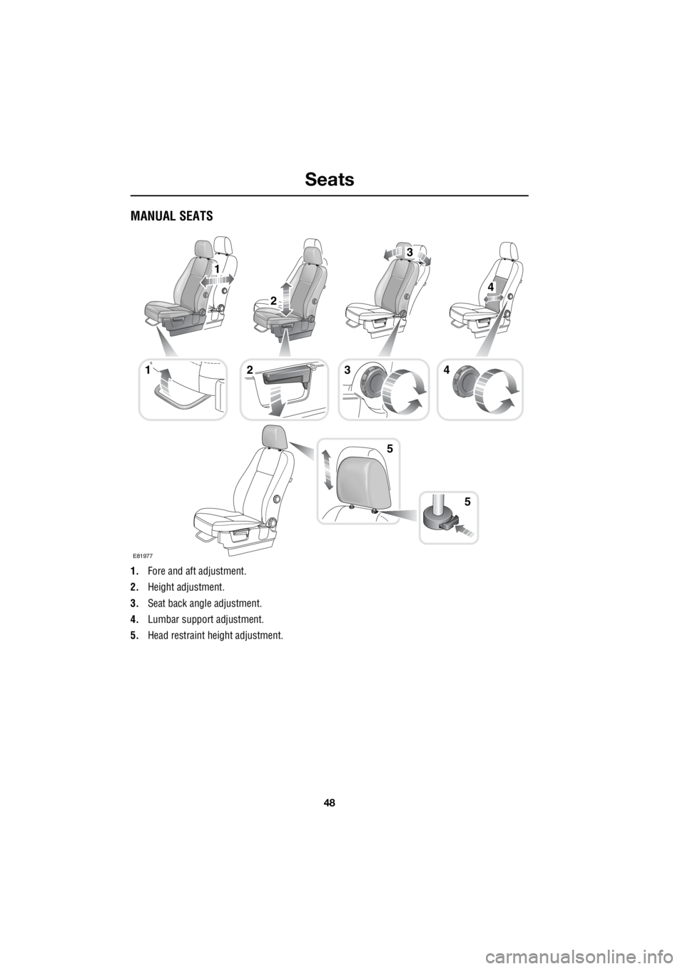
MANUAL SEATS
1. Fore and aft adjustment.
2. Height adjustment.
3. Seat back angle adjustment.
4. Lumbar support adjustment.
5. Head restraint he ight adjustment.
1
5
1
2
4
3
423
5
E81977
Page 2769 of 3229
49
Seats
R
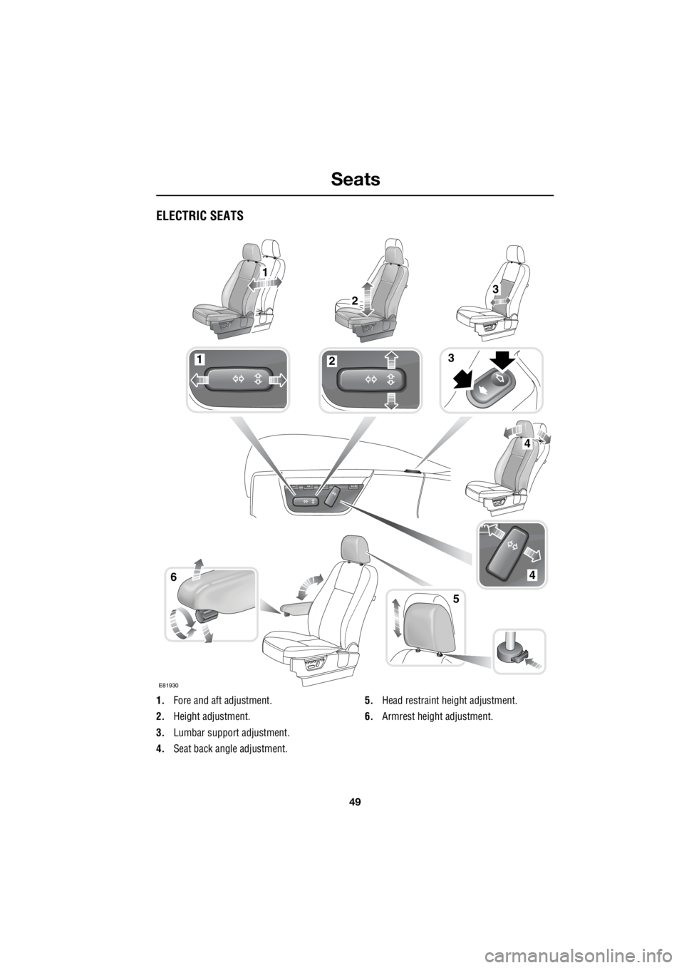
ELECTRIC SEATS
1. Fore and aft adjustment.
2. Height adjustment.
3. Lumbar support adjustment.
4. Seat back angle adjustment. 5.
Head restraint height adjustment.
6. Armrest height adjustment.
123
46
5
1
23
4
E81930