2006 LAND ROVER FRELANDER 2 turn signal
[x] Cancel search: turn signalPage 63 of 3229
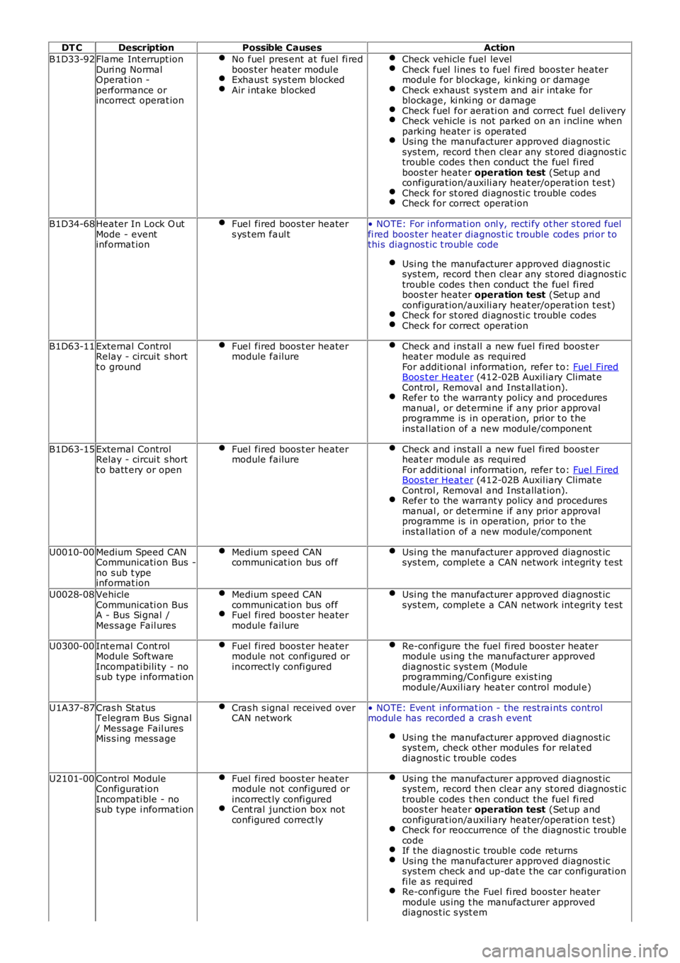
DT CDescriptionPossible CausesAction
B1D33-92Flame Int errupt ionDuri ng NormalOperat ion -performance orincorrect operat ion
No fuel pres ent at fuel fi redboos t er heat er modul eExhaus t sys t em blockedAir i nt ake blocked
Check vehicle fuel levelCheck fuel l ines t o fuel fired boos ter heatermodul e for bl ockage, ki nki ng or damageCheck exhaus t s yst em and ai r int ake forblockage, ki nki ng or damageCheck fuel for aerati on and correct fuel deliveryCheck vehicle i s not parked on an i ncl ine whenparking heater i s operatedUsi ng t he manufacturer approved diagnost icsys t em, record t hen clear any st ored di agnos ti ctroubl e codes t hen conduct the fuel fi redboos t er heater operation test (Set up andconfigurat ion/auxili ary heat er/operat ion t es t)Check for st ored di agnos ti c troubl e codesCheck for correct operat ion
B1D34-68Heater In Lock O utMode - eventinformat ion
Fuel fired boos t er heaters ys t em faul t• NOTE: For i nformati on onl y, recti fy ot her s t ored fuelfi red boos ter heat er diagnos t ic t rouble codes pri or tothi s diagnos t ic t rouble code
Usi ng t he manufacturer approved diagnost icsys t em, record t hen clear any st ored di agnos ti ctroubl e codes t hen conduct the fuel fi redboos t er heater operation test (Set up andconfigurat ion/auxili ary heat er/operat ion t es t)Check for st ored di agnos ti c troubl e codesCheck for correct operat ion
B1D63-11External ControlRelay - circui t s hortt o ground
Fuel fired boos t er heatermodule failureCheck and i ns t all a new fuel fi red boost erheat er modul e as requi redFor addit ional informati on, refer t o: Fuel FiredBoos t er Heat er (412-02B Auxil iary Climat eCont rol , Removal and Ins t allat ion).Refer to the warrant y policy and proceduresmanual , or det ermi ne if any prior approvalprogramme is in operat ion, pri or t o t heins tal lati on of a new modul e/component
B1D63-15External ControlRelay - circui t s hortt o batt ery or open
Fuel fired boos t er heatermodule failureCheck and i ns t all a new fuel fi red boost erheat er modul e as requi redFor addit ional informati on, refer t o: Fuel FiredBoos t er Heat er (412-02B Auxil iary Climat eCont rol , Removal and Ins t allat ion).Refer to the warrant y policy and proceduresmanual , or det ermi ne if any prior approvalprogramme is in operat ion, pri or t o t heins tal lati on of a new modul e/component
U0010-00Medium Speed CANCommunicati on Bus -no s ub t ypeinformat ion
Medium speed CANcommuni cat ion bus offUsi ng t he manufacturer approved diagnost icsys t em, compl et e a CAN network int egrit y t est
U0028-08VehicleCommunicati on BusA - Bus Si gnal /Mes sage Fail ures
Medium speed CANcommuni cat ion bus offFuel fired boos t er heatermodule failure
Usi ng t he manufacturer approved diagnost icsys t em, compl et e a CAN network int egrit y t est
U0300-00Int ernal Cont rolModule Soft wareIncompati bili ty - nos ub type i nformati on
Fuel fired boos t er heatermodule not configured orincorrect ly confi gured
Re-configure the fuel fi red boost er heat ermodul e us ing t he manufacturer approveddiagnos t ic s yst em (Moduleprogramming/Confi gure exis t ingmodul e/Auxil iary heat er control modul e)
U1A37-87Cras h St atusTelegram Bus Signal/ Mes sage Fail uresMis s ing mess age
Cras h s ignal received overCAN network• NOTE: Event i nformat ion - the rest rai nts controlmodul e has recorded a cras h event
Usi ng t he manufacturer approved diagnost icsys t em, check other modules for relat eddiagnos t ic t rouble codes
U2101-00Control ModuleConfigurat ionIncompati ble - nos ub type i nformati on
Fuel fired boos t er heatermodule not configured orincorrect ly confi guredCent ral junct ion box notconfigured correct ly
Usi ng t he manufacturer approved diagnost icsys t em, record t hen clear any st ored di agnos ti ctroubl e codes t hen conduct the fuel fi redboos t er heater operation test (Set up andconfigurat ion/auxili ary heat er/operat ion t es t)Check for reoccurrence of t he diagnost ic troubl ecodeIf t he diagnost ic troubl e code returnsUsi ng t he manufacturer approved diagnost icsys t em check and up-dat e t he car confi gurati onfi le as requi redRe-configure the Fuel fi red boos ter heatermodul e us ing t he manufacturer approveddiagnos t ic s yst em
Page 70 of 3229
Publi shed: 06-Jul-2011
General Information - Diagnostic Trouble Code (DTC) IndexDTC: Body
Control Module (BCM)
Des cript ion and Operat ion
• NOTE: If a cont rol module or component i s s uspect and the vehicl e remai ns under manufacturer warrant y, refer t o t heW arranty Pol icy and Procedures manual (s ect ion B1.2), or determine i f any pri or approval program is i n operat ion, beforet he replacement of a component.
• NOTE: Generic scan t ool s may not read the codes li st ed, or may read only 5-digi t codes . Match t he 5 digi ts from t he s cant ool t o t he fi rs t 5 di gi ts of the 7-digit code li s ted t o i dent ify the fault (the last 2 digi ts gi ve ext ra informati on read by themanufacturer-approved di agnos ti c s ys t em).
• NOTE: W hen performing volt age or res is t ance t est s , always use a digi tal mult imeter (DMM) accurat e t o t hree deci malplaces, and wi th an up-t o-date cal ibrat ion cert ificate. W hen tes ti ng res is t ance al ways take t he res is t ance of t he DMMleads i nt o account .
• NOTE: Check and recti fy bas ic faul ts before beginni ng diagnos t ic rout ines i nvol vi ng pinpoint t es t s.
• NOTE: Ins pect connect ors for s igns of water ingres s , and pins for damage and/or corros ion.
• NOTE: If DTCs are recorded and, aft er performi ng the pi npoi nt tes ts , a fault is not present , an int ermi tt ent concern maybe t he caus e. Always check for loose connect ions and corroded terminals .
For addit ional informat ion, refer t o: Communicati ons Net work (418-00 Modul e Communicati ons Net work, Des cript ion andOperat ion).
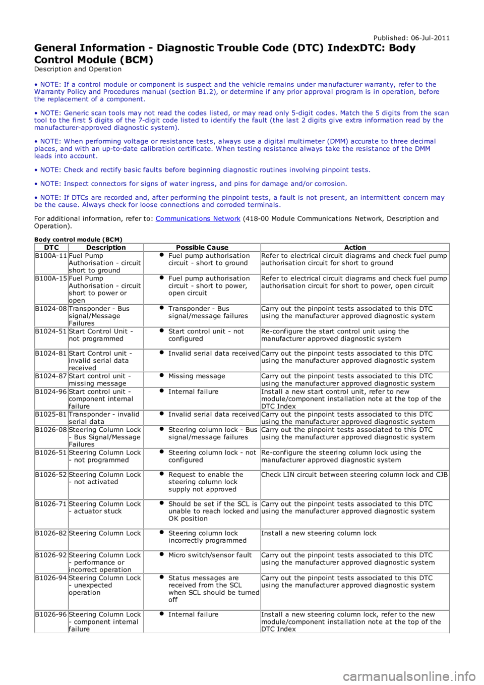
Body control module (BC M)
DT CDescriptionPossible CauseAction
B100A-11Fuel PumpAuthoris ati on - ci rcuits hort t o ground
Fuel pump authori s at ionci rcuit - s hort t o groundRefer to electrical ci rcuit diagrams and check fuel pumpaut hori sat ion circui t for s hort t o ground
B100A-15Fuel PumpAuthoris ati on - ci rcuits hort t o power oropen
Fuel pump authori s at ionci rcuit - s hort t o power,open circui t
Refer to electrical ci rcuit diagrams and check fuel pumpaut hori sat ion circui t for s hort t o power, open circui t
B1024-08Trans ponder - Buss ignal/Mess ageFailures
Trans ponder - Buss i gnal /mes s age fail uresCarry out the pi npoint t es ts as s oci at ed t o t his DTCusi ng t he manufact urer approved diagnost ic s ys tem
B1024-51Start Cont rol Uni t -not programmedSt art control uni t - notconfi guredRe-configure the st art control uni t usi ng themanufacturer approved diagnost ic sys tem
B1024-81Start Cont rol unit -invali d s eri al dat areceived
Inval id serial data recei vedCarry out the pi npoint t es ts as s oci at ed t o t his DTCusi ng t he manufact urer approved diagnost ic s ys tem
B1024-87Start cont rol unit -mi ss i ng mes sageMis si ng mes s ageCarry out the pi npoint t es ts as s oci at ed t o t his DTCusi ng t he manufact urer approved diagnost ic s ys tem
B1024-96Start cont rol unit -component int ernalfai lure
Internal fail ureIns t al l a new s t art cont rol unit , refer to newmodule/component i nst all at ion not e at t he top of t heDTC IndexB1025-81Trans ponder - invali ds eri al dat aInval id serial data recei vedCarry out the pi npoint t es ts as s oci at ed t o t his DTCusi ng t he manufact urer approved diagnost ic s ys temB1026-08Steering Column Lock- Bus Signal/Mes sageFailures
St eering col umn lock - Buss i gnal /mes s age fail uresCarry out the pi npoint t es ts as s oci at ed t o t his DTCusi ng t he manufact urer approved diagnost ic s ys tem
B1026-51Steering Column Lock- not programmedSt eering col umn lock - notconfi guredRe-configure the st eeri ng col umn lock us ing t hemanufacturer approved diagnost ic sys tem
B1026-52Steering Column Lock- not act ivat edRequest to enable thes t eering column locks upply not approved
Check LIN circui t bet ween s teering column l ock and CJB
B1026-71Steering Column Lock- actuator s t uckShould be set i f the SCL isunable to reach locked andO K posi ti on
Carry out the pi npoint t es ts as s oci at ed t o t his DTCusi ng t he manufact urer approved diagnost ic s ys tem
B1026-82Steering Column LockSt eering col umn locki ncorrectl y programmedIns t al l a new s t eering column lock
B1026-92Steering Column Lock- performance orincorrect operat ion
Micro s wi tch/s ens or faultCarry out the pi npoint t es ts as s oci at ed t o t his DTCusi ng t he manufact urer approved diagnost ic s ys tem
B1026-94Steering Column Lock- unexpectedoperati on
St atus mes s ages arerecei ved from t he SCLwhen SCL should be turnedoff
Carry out the pi npoint t es ts as s oci at ed t o t his DTCusi ng t he manufact urer approved diagnost ic s ys tem
B1026-96Steering Column Lock- component i nt ernalfai lure
Internal fail ureIns t al l a new s t eering column lock, refer t o t he newmodule/component i nst all at ion not e at t he top of t heDTC Index
Page 587 of 3229
11-Int egrated audio modul e
12-Int egrated control modul e
PRINCIPLES OF OPERATION
Windshield Wiper Switch
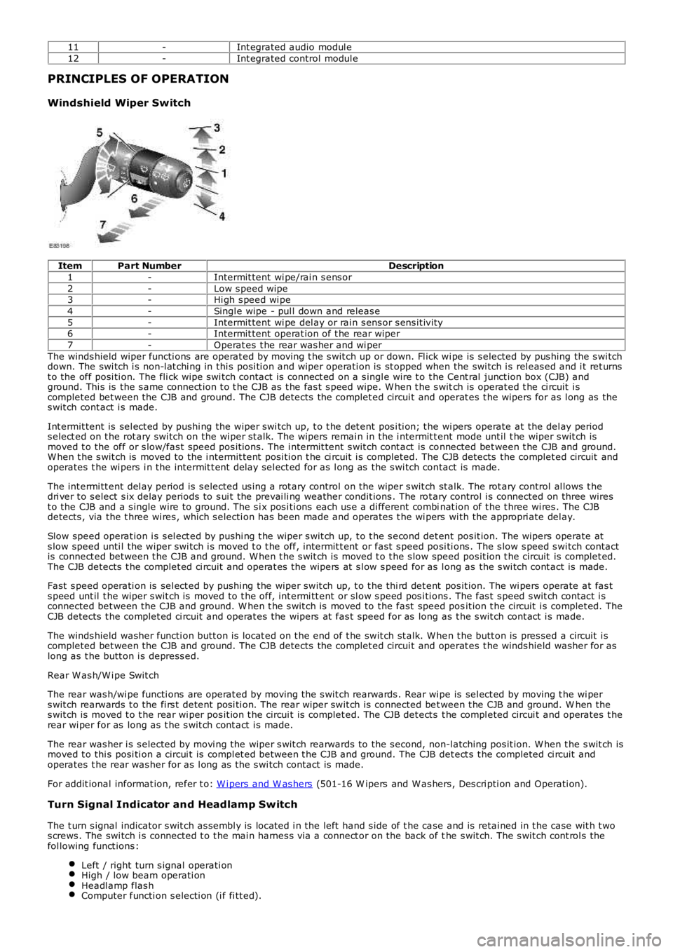
ItemPart NumberDescription
1-Intermit tent wi pe/rai n s ens or
2-Low s peed wipe3-Hi gh s peed wi pe
4-Singl e wipe - pul l down and releas e
5-Intermit tent wi pe del ay or rai n s ens or s ens it ivi ty6-Intermit tent operat ion of t he rear wiper
7-Operat es t he rear was her and wi per
The winds hield wiper functi ons are operat ed by moving t he s wit ch up or down. Fl ick wi pe is s elected by pus hing the s wi tchdown. The swi tch i s non-l at chi ng in thi s posi ti on and wiper operati on is st opped when the swi tch i s rel eas ed and i t ret urnst o the off posi ti on. The fli ck wipe s wi tch contact is connect ed on a s ingl e wire t o t he Cent ral junct ion box (CJB) andground. Thi s is the s ame connect ion t o t he CJB as t he fas t s peed wipe. W hen t he s witch is operat ed t he ci rcuit i scompleted bet ween the CJB and ground. The CJB detects the complet ed circui t and operat es t he wipers for as l ong as thes wit ch cont act i s made.
Int ermit tent is sel ect ed by pushi ng the wiper swi tch up, t o t he det ent pos i ti on; t he wi pers operate at the del ay periods elect ed on t he rot ary swi tch on the wi per st alk. The wipers remai n in the i ntermit tent mode unt il t he wiper s wit ch ismoved t o the off or s low/fas t speed pos it ions. The i ntermit tent s wit ch cont act is connected bet ween t he CJB and ground.W hen t he s wit ch is moved to the i ntermit tent posi ti on t he ci rcuit i s completed. The CJB detects the complet ed circuit andoperates t he wi pers i n the intermit t ent delay sel ect ed for as l ong as the s wi tch contact is made.
The int ermi tt ent del ay period is s elected us i ng a rot ary control on the wiper s wit ch st alk. The rot ary control al lows t hedri ver t o s elect s ix delay periods to s ui t the prevai li ng weather condit ions . The rot ary control i s connected on three wirest o the CJB and a s ingle wire to ground. The s i x pos i ti ons each us e a di fferent combinat ion of t he t hree wi res . The CJBdetects , via the t hree wi res , which s electi on has been made and operates t he wi pers wi th the appropri ate del ay.
Slow speed operat ion i s s el ect ed by pus hi ng t he wiper s wit ch up, t o t he s econd det ent pos it ion. The wipers operate ats low speed unti l the wiper swi tch i s moved t o t he off, intermit t ent or fast s peed posi ti ons . The s low s peed s wi tch contactis connect ed between t he CJB and ground. W hen t he s wit ch is moved t o t he s low speed pos it ion t he circuit is complet ed.The CJB detects t he complet ed ci rcuit and operat es the wipers at s l ow s peed for as long as the s wi tch cont act is made.
Fast s peed operati on is sel ect ed by pushi ng the wiper swit ch up, t o t he thi rd det ent pos it ion. The wi pers operate at fas ts peed unt il t he wiper s wit ch is moved to t he off, int ermi tt ent or sl ow s peed pos i ti ons . The fas t s peed s wit ch cont act i sconnected bet ween the CJB and ground. W hen t he s wit ch is moved to the fast speed posit ion t he circuit i s complet ed. TheCJB detects t he complet ed ci rcuit and operat es the wipers at fas t speed for as long as t he s wit ch cont act i s made.
The winds hield washer functi on butt on is locat ed on t he end of t he swit ch st alk. W hen t he butt on is pres sed a circuit i scompleted bet ween the CJB and ground. The CJB detects the complet ed circui t and operat es t he winds hield washer for aslong as t he butt on i s depress ed.
Rear W as h/W i pe Swit ch
The rear was h/wi pe functi ons are operat ed by moving t he s wit ch rearwards . Rear wi pe is sel ect ed by moving t he wi pers wit ch rearwards t o the fi rs t detent posi ti on. The rear wiper swit ch is connected bet ween t he CJB and ground. W hen thes wit ch is moved t o t he rear wi per pos it ion t he circui t is complet ed. The CJB det ect s t he compl eted circui t and operates t herear wi per for as long as t he s wit ch cont act i s made.
The rear was her i s s elected by movi ng the wiper s wit ch rearwards to the s econd, non-l atching pos it ion. W hen t he s wit ch ismoved t o thi s posi ti on a circui t is compl et ed between t he CJB and ground. The CJB det ect s t he completed ci rcuit andoperates t he rear was her for as l ong as the s wi tch contact is made.
For addit ional informat ion, refer t o: W i pers and W as hers (501-16 W ipers and W as hers , Des cri pti on and Operati on).
Turn Signal Indicator and Headlamp Switch
The t urn s ignal indicator s wit ch as sembl y is locat ed i n the left hand s ide of t he case and is retai ned in t he case wit h t wos crews . The swi tch i s connected t o t he mai n harnes s via a connect or on the back of the s wit ch. The s wit ch cont rol s thefol lowing funct ions :
Left / right turn s ignal operati onHigh / low beam operati onHeadl amp flas hComputer functi on s electi on (i f fi tt ed).
Page 998 of 3229
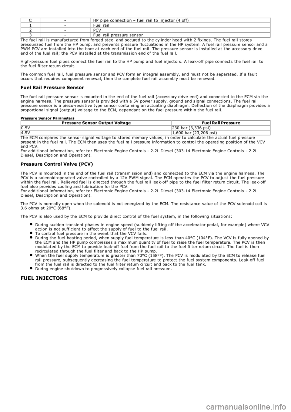
C-HP pipe connecti on – fuel rail t o inject or (4 off)
1-Fuel rail
2-PCV3-Fuel rail press ure sens or
The fuel rai l is manufact ured from forged st eel and secured t o t he cyl inder head with 2 fixings . The fuel rai l st orespres s urized fuel from t he HP pump, and prevent s pres s ure fluct uat ions i n the HP s ys tem. A fuel rail pres s ure s ens or and aPW M PCV are ins tall ed int o t he bore at each end of the fuel rail . The pres s ure s ensor i s ins tal led at t he acces sory dri veend of the fuel rail ; the PCV ins tal led at t he transmis s ion end of t he fuel rai l.
High-pres sure fuel pipes connect t he fuel rai l t o t he HP pump and fuel inject ors . A l eak-off pipe connect s the fuel rail t ot he fuel fi lt er return circui t.
The common fuel rail, fuel press ure s ens or and PCV form an int egral as s embly, and mus t not be separat ed. If a faultoccurs that requires component renewal, t hen t he compl ete fuel rail as s embl y mus t be renewed.
Fuel Rail Pressure Sensor
The fuel rai l pres sure s ens or is mount ed i n t he end of the fuel rail (access ory drive end) and connected to t he ECM vi a t heengi ne harnes s. The press ure sens or is provi ded wit h a 5V power s upply, ground and signal connect ions . The fuel railpres s ure s ensor i s a pi ezo-res is ti ve type s ens or contai ni ng an actuati ng diaphragm. Deflect ion of t he diaphragm provides aproport ional si gnal (output) volt age t o t he ECM, dependant on t he fuel pres s ure wit hin t he fuel rai l.
Pressure Sensor ParametersPressure Sensor Output VoltageFuel Rail Pressure
0.5V230 bar (3,336 ps i)
4.5V1,600 bar (23,206 ps i)The ECM compares t he s ens or s ignal vol tage t o s tored memory val ues, i n order t o cal cul ate the actual fuel pres s urepres ent in t he fuel rail. The ECM then us es t he fuel rai l press ure informat ion t o cont rol t he operati ng posi ti on of the VCVand PCV.For addit ional informat ion, refer t o: Electroni c Engi ne Controls - 2.2L Dies el (303-14 El ect ronic Engine Cont rols - 2.2LDies el, Des cript ion and Operat ion).
Pressure Control Valve (PCV)
The PCV i s mounted i n t he end of the fuel rail (trans mi s si on end) and connect ed t o the ECM via t he engine harnes s . ThePCV i s a s olenoid-operat ed valve cont rol led by a 12V PW M si gnal . The ECM operat es the PCV to adjus t t he fuel pres s urewit hin the fuel rail . Rel ieved fuel is direct ed through t he fuel rail leak-off pipe t o t he fuel fi lt er ret urn circui t. The l eak-offfuel als o provi des cooli ng and lubricat ion for t he PCV.For addit ional informat ion, refer t o: Electroni c Engi ne Controls - 2.2L Dies el (303-14 El ect ronic Engine Cont rols - 2.2LDies el, Des cript ion and Operat ion).
The PCV i s normall y open when t he s ol enoi d is not energi zed by the ECM. The resi s tance val ue of the PCV sol enoi d coi l is3.6 ohms at 20°C (68°F).
The PCV i s als o us ed by t he ECM t o provide di rect cont rol of the fuel sys tem, in t he fol lowi ng si tuat ions :
Duri ng s udden t rans ient phas es i n engine s peed (s uddenl y li ft ing off the accel erat or pedal, for example) where VCVact ion is not s ufficient to affect t he s uppl y of fuel to the fuel rail .To cont rol fuel press ure in t he event that the VCV fai ls .Duri ng the fuel heat ing period, when supply fuel temperat ure is l ess than 40°C (104°F). The VCV i s ful ly opened byt he ECM and t he HP pump compres s es a maximum quanti ty of fuel t o rais e t he fuel t emperature. The PCV is t henmodulat ed by the ECM to provide l eak-off fuel from the fuel rail t o t he fuel fi lt er ret urn circui t. The fuel i s t henrecircul ated t hrough t he fuel fi lt er and back t o t he HP pump.W hen t he fuel s uppl y t emperature is greater t han 70°C (158°F). The PCV is modul ated by t he ECM t o releas e fuelrai l pres sure, s ubs equentl y decreasi ng the fuel temperat ure to protect the fuel sys tem component s. Leak-off fuelfrom the fuel rail is direct ed to the fuel fil ter return ci rcuit and back t o the fuel tank.Duri ng engi ne s hut down t o progres s ively coll aps e fuel rail pres s ure.
FUEL INJECTORS
Page 1647 of 3229
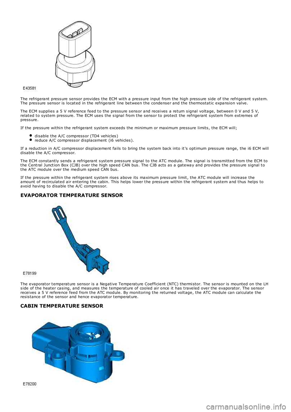
The refrigera nt press ure sensor provides the ECM wi th a pre ssure input from the high press ure side of t he refri gera nt s yste m.The pres sure sensor is locat ed in the ref rige rant line be twee n the conde nse r and the thermosta tic expa nsion valve .
The ECM supplie s a 5 V reference fe ed t o the pressure s ens or a nd recei ves a re turn signal volta ge, bet wee n 0 V and 5 V,relat ed t o system pressure. The ECM use s the s igna l from t he s ensor to protect the ref rigerant sys tem from extremes ofpress ure .
If the pre ssure withi n the re frige rant sys tem exceeds the minimum or maximum pre ssure li mits , the ECM will;
disable the A/C compress or (TD4 vehicles )re duce A/C compress or di spla cement (i6 vehi cles ).
If a reduction in A/C compre ssor displace me nt fa ils to bring the sys tem back into it's optimum pres sure range, the i6 ECM willdisable t he A/C compres sor.
The ECM constantly sends a refrigera nt s yst em pres sure signal to the ATC module. The signal i s tra nsmitte d from the ECM tot he Cent ral Junct ion Box (CJB) over the high spe ed CAN bus . The CJB acts a s a gate way and provides t he press ure signal t ot he ATC module over the me dium speed CAN bus.
If the pre ssure withi n the re frige rant sys tem rise s a bove its ma ximum press ure limit, the ATC module will incre ase thea mount of re circulate d a ir enteri ng t he cabin. This helps lower t he press ure wit hin t he refrigera nt s yste m a nd t hus helps toa void ha ving to disa ble t he A/C compres sor.
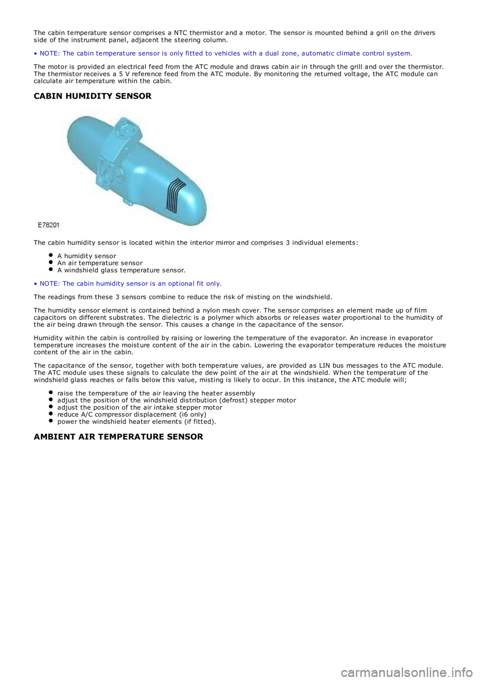
EVAPORATOR TEMPERATURE SENSOR
The e vaporat or t emperat ure sensor is a Negative Te mpe rature Coef ficie nt (NTC) the rmistor. The se nsor is mounted on the LHs ide of the heate r ca sing, and meas ures the temperature of cooled air once it has t rave led ove r the evaporator. The se nsorrecei ves a 5 V re fere nce feed from the ATC module. By monitori ng t he returned volt age , the ATC module ca n ca lcul ate theresis tance of the sensor and hence e vaporat or t emperat ure.
CABIN TEMPERATURE SENSOR
Page 1648 of 3229
The cabin te mpe rature s ensor comprises a NTC thermist or a nd a motor. The sensor is mounted behind a grill on the driverss ide of the instrume nt panel , adjace nt t he s teering column.
• NO TE: The cabin te mperat ure sens or i s only fi tted to vehi cles with a dual zone, a utomati c cli mat e control system.
The motor is provide d an ele ctrical f eed from the ATC module and draws ca bin a ir in through the grill a nd over the thermis tor.The t hermist or re ceives a 5 V re fere nce feed from the ATC module. By moni toring the re turned volt age, the ATC modul e ca ncalculate air tempera ture wit hin the cabin.
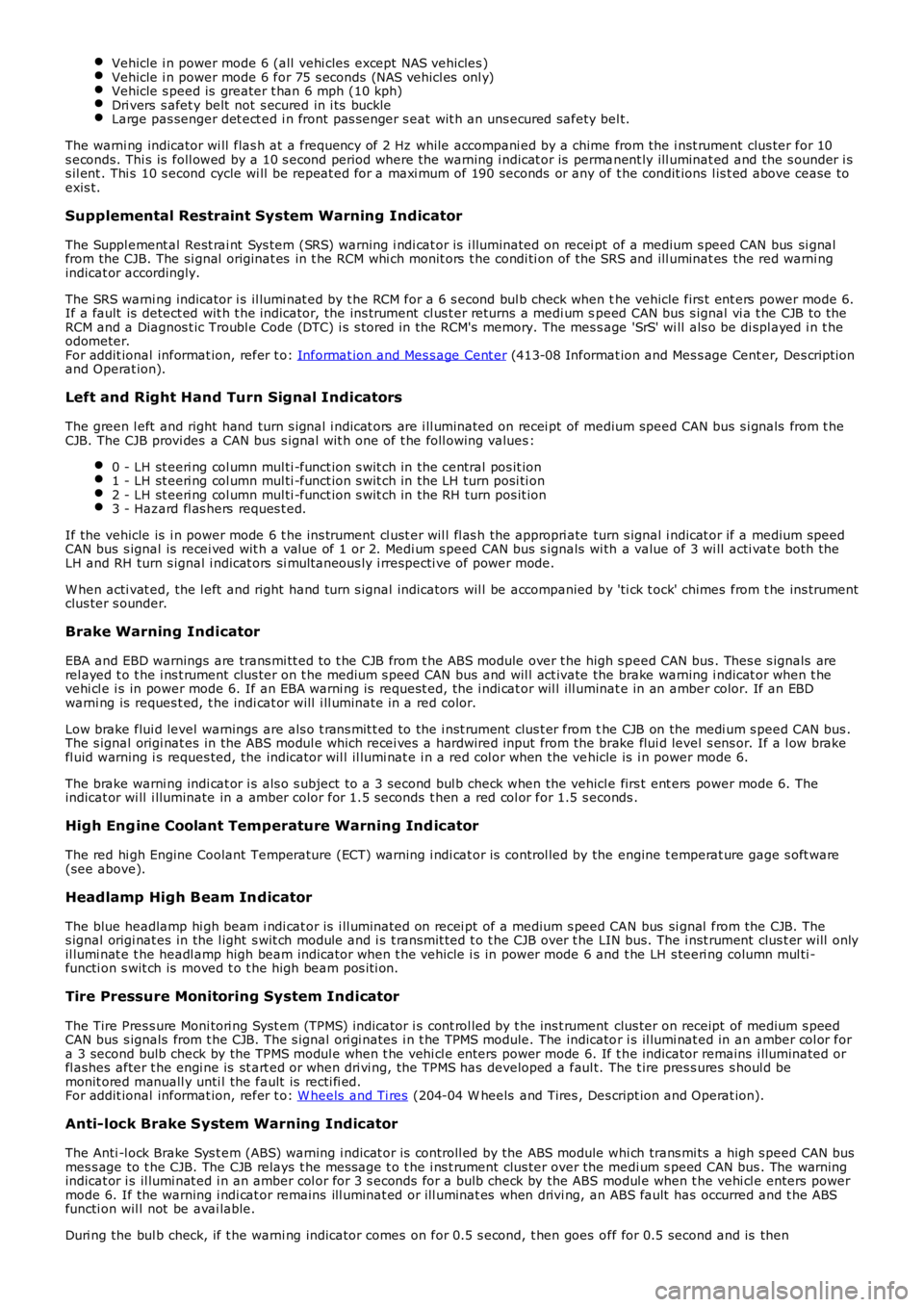
CABIN HUMIDITY SENSOR
The cabin humidity s ens or is located wit hin the inte rior mirror a nd comprise s 3 individual el eme nts :
A humidit y se nsorAn ai r temperature se nsorA windshi eld glas s te mpe rature s ens or.
• NO TE: The cabin humidity sens or i s an opt iona l fit onl y.
The readings from these 3 s ensors combine to reduce the ri sk of mi sting on the windshield.
The humidity sensor element is cont aine d behind a nylon mesh cove r. The s ens or comprise s an ele ment made up of fil mcapa citors on dif fere nt s ubst rate s. The diele ctric is a polyme r which abs orbs or rele ases wa ter proportional to t he humidity oft he a ir being dra wn t hrough the sensor. This causes a change in the capacit ance of the sensor.
Humidity wit hin the cabi n is controll ed by ra ising or lowering the te mpe rature of the evaporator. An increas e in eva poratort emperat ure increase s the moist ure cont ent of t he a ir in the cabin. Lowering the evaporator tempe rature re duces t he mois tureconte nt of the ai r in the cabin.
The capa cita nce of t he s ensor, t oget her with both te mperat ure values, are provided as LIN bus me ssages t o the ATC module.The ATC module use s these signals to calculate the dew point of the ai r at the windshi eld. W hen t he t emperat ure of t hewindshie ld glass rea ches or falls bel ow t his value, misti ng i s likely to occur. In this inst ance, the ATC module will;
ra ise the tempera ture of the air l eaving t he heat er a ssemblya djus t the position of the windshield dis tribution (de fros t) s tepper motora djus t the position of the air inta ke stepper mot orre duce A/C compress or di spla cement (i6 only)powe r the windshield hea ter element s (if fitt ed).
AMBIENT AIR TEMPERATURE SENSOR
Page 1771 of 3229
Vehicle i n power mode 6 (all vehi cles except NAS vehicles )Vehicle i n power mode 6 for 75 s econds (NAS vehicl es onl y)Vehicle s peed is greater t han 6 mph (10 kph)Dri vers s afet y belt not s ecured in i ts buckleLarge pas senger det ect ed i n front pas s enger s eat wit h an uns ecured safety bel t.
The warni ng indicator wi ll flas h at a frequency of 2 Hz while accompani ed by a chime from the i nst rument clus ter for 10s econds. Thi s is foll owed by a 10 s econd period where the warning i ndicat or is permanent ly ill uminat ed and the s ounder i ss il ent . Thi s 10 s econd cycle wi ll be repeat ed for a maxi mum of 190 seconds or any of t he condit ions l is t ed above cease toexis t.
Supplemental Restraint System Warning Indicator
The Suppl ement al Rest rai nt Sys tem (SRS) warning i ndi cat or is i lluminated on recei pt of a medium s peed CAN bus si gnalfrom the CJB. The si gnal originat es in t he RCM whi ch monit ors t he condi ti on of the SRS and ill uminat es the red warni ngindicat or accordingly.
The SRS warni ng indicator i s il lumi nat ed by t he RCM for a 6 s econd bul b check when the vehicle firs t ent ers power mode 6.If a fault is detect ed wit h t he indicator, the ins trument cl us t er returns a medi um speed CAN bus s ignal vi a t he CJB to theRCM and a Diagnos t ic Troubl e Code (DTC) i s s tored in the RCM's memory. The mes s age 'SrS' wi ll als o be di spl ayed i n t heodometer.For addit ional informat ion, refer t o: Informat ion and Mes s age Cent er (413-08 Informat ion and Mes s age Cent er, Des cript ionand Operat ion).
Left and Right Hand Turn Signal Indicators
The green l eft and right hand turn s ignal i ndicat ors are i ll uminated on recei pt of medium speed CAN bus s i gnals from t heCJB. The CJB provi des a CAN bus s ignal wit h one of t he foll owing values :
0 - LH st eeri ng col umn mul ti -funct ion s wit ch in the central pos it ion1 - LH st eeri ng col umn mul ti -funct ion s wit ch in the LH turn posi ti on2 - LH st eeri ng col umn mul ti -funct ion s wit ch in the RH turn pos it ion3 - Hazard fl as hers reques t ed.
If the vehicle is i n power mode 6 t he ins trument cl ust er wil l fl as h the appropri ate turn s ignal i ndicat or if a medium speedCAN bus s ignal is recei ved wit h a value of 1 or 2. Medi um s peed CAN bus s ignals wi th a value of 3 wi ll acti vat e both theLH and RH turn s ignal i ndicat ors si mult aneous ly i rrespecti ve of power mode.
W hen acti vat ed, the l eft and right hand turn s ignal indicators wil l be accompanied by 'ti ck t ock' chimes from t he ins trumentclus ter s ounder.
Brake Warning Indicator
EBA and EBD warnings are trans mi tt ed t o t he CJB from t he ABS module over t he high s peed CAN bus . Thes e s ignals arerel ayed t o t he i ns t rument clus ter on t he medium s peed CAN bus and wil l act ivate the brake warning i ndicat or when t hevehi cl e i s in power mode 6. If an EBA warni ng is request ed, the i ndi cat or wil l ill uminat e in an amber color. If an EBDwarni ng is reques t ed, t he indi cat or will i ll uminate in a red color.
Low brake flui d level warnings are als o t rans mit t ed to the i nst rument clus t er from the CJB on the medi um s peed CAN bus .The s ignal origi nat es in the ABS modul e which recei ves a hardwired input from the brake flui d level s ens or. If a l ow brakefl uid warning i s reques ted, the indicator wil l il lumi nat e i n a red col or when the vehicle is i n power mode 6.
The brake warni ng indi cat or i s als o s ubject t o a 3 second bul b check when the vehicle firs t ent ers power mode 6. Theindicat or wi ll i lluminate in a amber color for 1.5 s econds t hen a red col or for 1.5 s econds .
High Eng ine Coolant Temperature Warning Ind icator
The red hi gh Engine Coolant Temperature (ECT) warning i ndi cat or is control led by the engine t emperat ure gage s oft ware(see above).
Headlamp High Beam Indicator
The blue headlamp hi gh beam i ndi cat or is i ll uminated on recei pt of a medium s peed CAN bus si gnal from the CJB. Thes ignal origi nat es in the l ight s wit ch module and i s t ransmit ted t o t he CJB over t he LIN bus. The i nst rument clus t er will onlyil lumi nat e t he headl amp high beam indicator when t he vehicle i s in power mode 6 and t he LH s teeri ng column mul ti -functi on s wit ch is moved t o t he high beam pos i ti on.
Tire Pressure Monitoring System Indicator
The Tire Pres s ure Moni tori ng Syst em (TPMS) indicator i s cont rol led by t he ins t rument clus ter on receipt of medium s peedCAN bus s ignals from t he CJB. The s ignal ori gi nates i n t he TPMS module. The indicator i s il lumi nat ed in an amber col or fora 3 second bulb check by the TPMS modul e when t he vehi cl e enters power mode 6. If t he indicator remains i lluminated orfl ashes after t he engi ne is st art ed or when dri vi ng, the TPMS has developed a faul t. The t ire pres s ures s houl d bemonit ored manuall y unti l the fault is recti fi ed.For addit ional informat ion, refer t o: W heels and Ti res (204-04 W heels and Tires , Des cript ion and Operat ion).
Anti-lock Brake System Warning Indicator
The Anti -l ock Brake Sys t em (ABS) warning i ndicat or is controll ed by the ABS module whi ch trans mi ts a high s peed CAN busmes s age to t he CJB. The CJB relays t he mes sage t o t he i ns t rument clus ter over the medi um s peed CAN bus . The warningindicat or i s il lumi nat ed i n an amber col or for 3 s econds for a bulb check by the ABS modul e when t he vehi cl e enters powermode 6. If the warning i ndi cat or remains ill uminat ed or ill uminat es when drivi ng, an ABS fault has occurred and t he ABSfuncti on wil l not be avai lable.
Duri ng the bul b check, if t he warni ng indicator comes on for 0.5 s econd, t hen goes off for 0.5 second and is then
Page 1920 of 3229
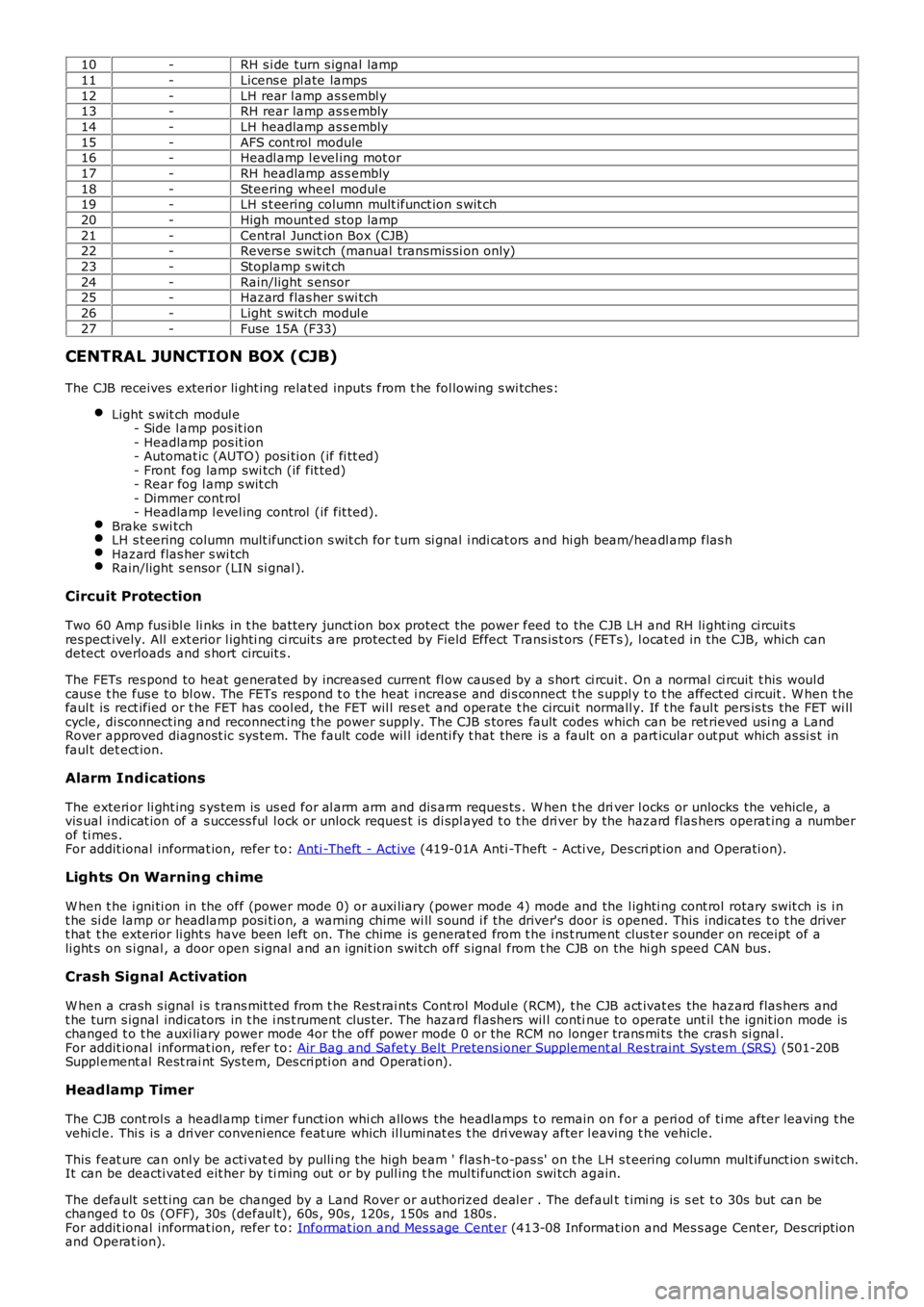
10-RH s i de turn s ignal lamp
11-Licens e pl ate lamps
12-LH rear l amp as s embl y13-RH rear lamp as s embly
14-LH headlamp as s embly
15-AFS cont rol module16-Headl amp l evel ing mot or
17-RH headlamp as s embly
18-Steering wheel modul e19-LH s t eering column mult ifunct ion s wit ch
20-High mount ed s top lamp
21-Central Junct ion Box (CJB)22-Revers e s wit ch (manual transmis si on only)
23-Stoplamp s wit ch
24-Rain/light s ensor25-Hazard flas her s wi tch
26-Light s wit ch modul e
27-Fuse 15A (F33)
CENTRAL JUNCTION BOX (CJB)
The CJB receives exteri or li ght ing relat ed inputs from t he fol lowing s wi tches:
Light s wit ch modul e- Side l amp pos it ion- Headlamp pos it ion- Automat ic (AUTO) posi ti on (if fi tt ed)- Front fog lamp swi tch (if fit ted)- Rear fog l amp s wit ch- Dimmer cont rol- Headlamp l evel ing control (if fit ted).Brake s wi tchLH s t eering column mult ifunct ion s wit ch for t urn si gnal i ndi cat ors and hi gh beam/headl amp flas hHazard flas her s wi tchRain/light s ensor (LIN si gnal ).
Circuit Protection
Two 60 Amp fus ibl e li nks in t he batt ery junct ion box protect the power feed to the CJB LH and RH li ght ing ci rcuit sres pect ively. All ext erior l ighti ng ci rcuit s are prot ect ed by Field Effect Trans is t ors (FETs ), l ocat ed in the CJB, which candetect overloads and s hort circuit s .
The FETs res pond to heat generated by increased current fl ow caus ed by a s hort ci rcuit . On a normal ci rcuit t his woul dcaus e t he fus e to bl ow. The FETs respond t o t he heat i ncrease and di s connect t he s uppl y t o t he affect ed ci rcuit . W hen t hefaul t is rect ified or t he FET has cool ed, t he FET wil l res et and operate t he circui t normall y. If t he faul t pers is ts the FET wi llcycle, di sconnect ing and reconnect ing t he power supply. The CJB s tores fault codes which can be ret rieved usi ng a LandRover approved diagnost ic sys tem. The fault code wil l identi fy t hat there is a fault on a part icular out put which as si s t infaul t det ect ion.
Alarm Indications
The exteri or li ght ing s ys tem is us ed for al arm arm and dis arm reques ts . W hen t he driver l ocks or unlocks the vehicle, avis ual i ndicat ion of a s uccess ful l ock or unlock reques t is di spl ayed t o t he dri ver by the hazard flas hers operat ing a numberof ti mes .For addit ional informat ion, refer t o: Anti -Theft - Act ive (419-01A Anti -Theft - Acti ve, Des cri pt ion and Operati on).
Lights On Warning chime
W hen t he i gni ti on in the off (power mode 0) or auxi liary (power mode 4) mode and the l ighti ng cont rol rotary swit ch is i nt he si de lamp or headlamp posi ti on, a warning chime wi ll s ound i f the driver's door is opened. This indicates t o t he dri vert hat t he exterior li ght s have been left on. The chime is generat ed from t he i ns t rument clus ter s ounder on receipt of ali ght s on s i gnal , a door open s ignal and an ignit ion swi tch off s ignal from t he CJB on the hi gh s peed CAN bus.
Crash Signal Activation
W hen a crash s ignal i s t rans mit ted from t he Rest rai nts Cont rol Modul e (RCM), t he CJB act ivat es the hazard flas hers andt he turn s ignal indicators in t he i ns t rument clus ter. The hazard fl ashers wil l continue to operate unt il t he ignit ion mode ischanged t o t he auxi liary power mode 4or the off power mode 0 or the RCM no longer trans mi ts the cras h si gnal .For addit ional informat ion, refer t o: Air Bag and Safet y Belt Pretens ioner Supplement al Res traint Syst em (SRS) (501-20BSuppl ement al Rest rai nt Sys tem, Des cri pti on and Operati on).
Headlamp Timer
The CJB cont rol s a headl amp t imer funct ion whi ch allows the headlamps t o remain on for a peri od of ti me after leaving t hevehi cl e. Thi s is a dri ver conveni ence feat ure which il lumi nat es t he dri veway after leaving t he vehicle.
This feat ure can onl y be acti vat ed by pulli ng t he high beam ' flas h-t o-pas s' on t he LH s t eering column mult ifunct ion s wi tch.It can be deacti vat ed eit her by ti ming out or by pull ing t he mul ti funct ion swi tch again.
The default s ett ing can be changed by a Land Rover or authorized deal er . The default t imi ng is s et t o 30s but can bechanged t o 0s (OFF), 30s (defaul t), 60s , 90s , 120s , 150s and 180s .For addit ional informat ion, refer t o: Informat ion and Mes s age Cent er (413-08 Informat ion and Mes s age Cent er, Des cript ionand Operat ion).