2006 LAND ROVER FRELANDER 2 remote start
[x] Cancel search: remote startPage 804 of 3229
1
2
3
4
5
6
7
8
9
10
11
12
1
2
3
1
2
3
4
5
6
7
8
9
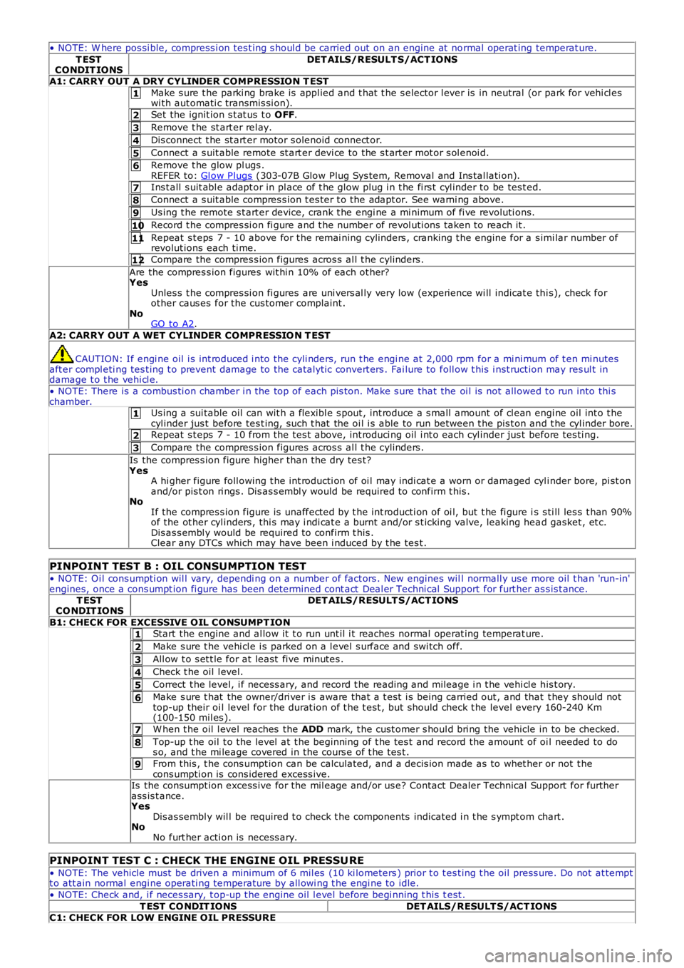
• NOTE: W here pos si ble, compress i on tes t ing s houl d be carried out on an engine at normal operat ing temperat ure.
T ESTCONDIT IONSDET AILS/RESULT S/ACT IONS
A1: CARRY OUT A DRY CYLINDER COMPRESSION T EST
Make s ure t he parki ng brake is appl ied and t hat t he s elector l ever is in neutral (or park for vehi cl eswi th aut omati c transmis si on).
Set the ignit ion s t at us t o OFF.
Remove t he st art er rel ay.
Dis connect t he st art er motor s olenoid connect or.
Connect a s uit able remote st art er devi ce to the s t art er mot or s ol enoi d.
Remove t he glow pl ugs .REFER to: Gl ow Plugs (303-07B Glow Plug Sys tem, Removal and Ins tal lati on).
Ins t all s uit abl e adapt or in pl ace of t he glow plug i n t he fi rs t cyl inder to be tes t ed.
Connect a s uit able compres s ion t es ter t o the adapt or. See warni ng above.
Us ing t he remote s t art er device, crank t he engi ne a mi nimum of fi ve revoluti ons.
Record t he compres si on fi gure and t he number of revol uti ons taken to reach it .
Repeat s t eps 7 - 10 above for t he remai ning cylinders , cranking t he engine for a s imi lar number ofrevolut ions each ti me.
Compare the compres s ion figures acros s al l t he cylinders .
Are the compres s ion figures wit hi n 10% of each ot her?YesUnles s t he compres si on fi gures are uni vers al ly very low (experience wi ll indicat e thi s), check forother caus es for the cus tomer complaint .NoGO to A2.
A2: CARRY OUT A WET CYLINDER COMPRESSIO N T EST
CAUTION: If engi ne oil i s int roduced i nto the cyli nders, run t he engi ne at 2,000 rpm for a mi ni mum of t en mi nutesaft er compl eti ng tes t ing t o prevent damage to the catal yt ic convert ers . Fai lure to foll ow t his i nst ruct ion may res ul t indamage t o t he vehi cl e.
• NOTE: There is a combus ti on chamber i n the top of each pis ton. Make s ure that the oi l is not all owed t o run into thi schamber.Us ing a sui table oil can wit h a flexibl e s pout , int roduce a s mall amount of cl ean engi ne oil int o t hecyl inder jus t before tes t ing, such t hat the oi l i s able to run between t he pis t on and t he cyl inder bore.Repeat s t eps 7 - 10 from the tes t above, int roduci ng oil i nt o each cyl inder jus t before tes ti ng.
Compare the compres s ion figures acros s al l t he cylinders .
Is the compres s ion figure higher than t he dry tes t?YesA hi gher figure foll owing t he int roducti on of oi l may indi cat e a worn or damaged cyli nder bore, pi st onand/or pis t on ri ngs . Dis as s embl y would be required to confirm t his .NoIf the compres s ion figure is unaffect ed by t he int roducti on of oi l, but t he fi gure is s ti ll les s t han 90%of the ot her cyl inders , thi s may i ndi cat e a burnt and/or s t icking valve, leaking head gasket , et c.Dis as s embl y would be required to confirm t his .Clear any DTCs which may have been i nduced by t he tes t .
PINPOINT TEST B : OIL CONSUMPTION TEST
• NOTE: Oi l cons umpti on wil l vary, dependi ng on a number of fact ors . New engines will normall y us e more oil t han 'run-in'engines, once a cons umpt ion fi gure has been det ermined cont act Deal er Techni cal Support for furt her as s is t ance.T ESTCO NDIT IONSDET AILS/RESULT S/ACT IONS
B1: CHECK FOR EXCESSIVE OIL CONSUMPT IONStart the engine and al low it t o run unt il i t reaches normal operat ing temperat ure.
Make s ure t he vehi cl e i s parked on a l evel s urface and swi tch off.
All ow t o s et t le for at least five minutes .
Check t he oil l evel.
Correct t he level, i f necess ary, and record t he reading and mileage i n t he vehi cl e his t ory.
Make s ure t hat the owner/dri ver i s aware that a t est i s being carried out , and that t hey should nottop-up their oi l level for the durat ion of t he t est , but should check t he level every 160-240 Km(100-150 mil es ).
W hen t he oil l evel reaches the ADD mark, t he cust omer s houl d bri ng the vehicle in to be checked.
Top-up t he oil t o the level at t he beginning of t he tes t and record the amount of oil needed to dos o, and t he mi leage covered in the cours e of t he tes t .
From this , t he cons umpt ion can be calculated, and a decis ion made as to whet her or not t hecons umpti on is cons idered excess ive.Is the consumpt ion excess ive for the mil eage and/or us e? Contact Dealer Technical Support for furtherass is t ance.YesDis as sembl y wil l be required t o check t he components indicated i n t he s ympt om chart .NoNo furt her acti on is necess ary.
PINPOINT TEST C : CHECK THE ENGINE OIL PRESSU RE
• NOTE: The vehicle must be driven a minimum of 6 mil es (10 ki lometers ) prior t o t est ing t he oil press ure. Do not at temptt o att ain normal engi ne operati ng temperature by all owi ng t he engi ne to idle.
• NOTE: Check and, i f neces sary, t op-up t he engine oil l evel before begi nning t his test .
T EST CO NDIT IONSDET AILS/RESULT S/ACT IONSC1: CHECK FOR LOW ENGINE OIL PRESSURE
Page 1083 of 3229
Publi s hed: 11-May-2011
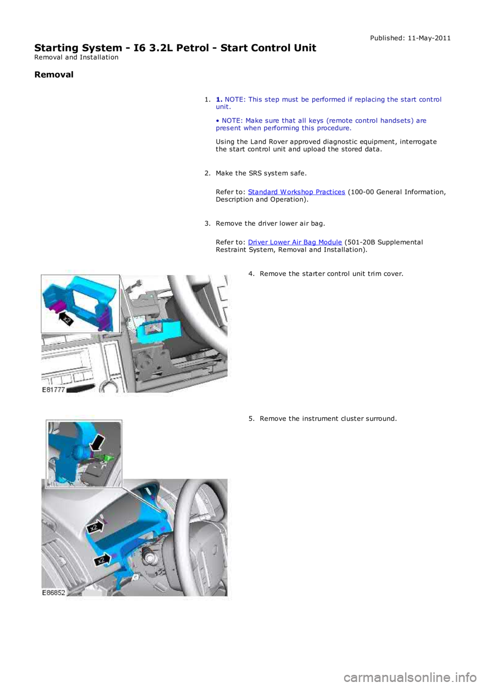
Starting System - I6 3.2L Petrol - Start Control Unit
Removal and Inst all ati on
Removal
1. NOTE: Thi s s tep must be performed i f replacing t he s tart cont rolunit .
• NOTE: Make s ure that all keys (remote cont rol hands ets ) arepres ent when performi ng thi s procedure.
Us ing t he Land Rover approved diagnost ic equipment , int errogat et he s tart cont rol uni t and upload t he s tored dat a.
1.
Make t he SRS s ys t em s afe.
Refer t o: Standard W orks hop Pract ices (100-00 General Informat ion,Des cript ion and Operat ion).
2.
Remove t he dri ver l ower ai r bag.
Refer t o: Dri ver Lower Air Bag Module (501-20B SupplementalRes traint Sys t em, Removal and Inst all at ion).
3.
Remove t he s tart er cont rol unit t ri m cover.4.
Remove t he ins trument cl ust er s urround.5.
Page 1092 of 3229
Publi s hed: 11-May-2011
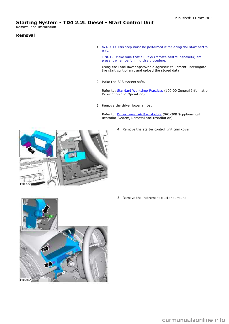
Starting System - TD4 2.2L Diesel - Start Control Unit
Removal and Inst all ati on
Removal
1. NOTE: Thi s s tep must be performed i f replacing t he s tart cont rol
unit .
• NOTE: Make s ure that all keys (remote cont rol hands ets ) are
pres ent when performi ng thi s procedure.
Us ing t he Land Rover approved diagnost ic equipment , int errogat e
t he s tart cont rol uni t and upload t he s tored dat a.
1.
Make t he SRS s ys t em s afe.
Refer t o: Standard W orks hop Pract ices (100-00 General Informat ion,
Des cript ion and Operat ion).
2.
Remove t he dri ver l ower ai r bag.
Refer t o: Dri ver Lower Air Bag Module (501-20B Supplemental
Res traint Sys t em, Removal and Inst all at ion).
3. Remove t he s tart er cont rol unit t ri m cover.
4. Remove t he ins trument cl ust er s urround.
5.
Page 1107 of 3229
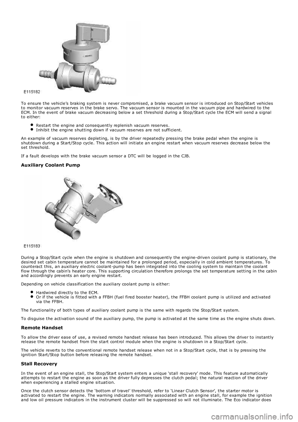
To ens ure t he vehi cl e’s braki ng s ys t em i s never compromi sed, a brake vacuum s ens or is int roduced on Stop/St art vehiclest o monit or vacuum reserves in t he brake s ervo. The vacuum sens or is mount ed in the vacuum pipe and hardwi red to t heECM. In the event of brake vacuum decreas ing below a s et threshold during a Stop/St art cycl e t he ECM wi ll s end a s ignalt o eit her:
Rest art t he engine and consequentl y replenis h vacuum reserves .Inhi bi t t he engi ne s hut ti ng down if vacuum res erves are not s uffi ci ent.
An example of vacuum res erves deplet ing, is by t he dri ver repeat edly pres s ing t he brake pedal when the engine iss hut down duri ng a St art/Stop cycle. This acti on wil l init iat e an engine res tart when vacuum reserves decreas e below thes et thres hold.
If a fault develops wi th the brake vacuum s ensor a DTC wil l be logged in the CJB.
Auxiliary Coolant Pump
Duri ng a St op/Start cycle when the engine i s s hutdown and consequent ly the engine-driven coolant pump is st ati onary, thedesi red s et cabi n t emperature cannot be mai ntai ned for a prol onged period, especially in col d ambient t emperatures . Tocount eract this , an auxil iary el ect ri c cool ant -pump has been integrat ed i nt o t he cool ing s ys tem to maint ain t he cool antfl ow t hrough t he cabi n’s heat er core. Thi s s upporti ng ci rculat ion t herefore prol ongs t he s et temperat ure set ti ng in the cabinand accordi ngl y prevents an early engine res tart.
Dependi ng on vehi cl e clas s ifi cat ion the auxil iary coolant pump i s eit her:
Hardwi red di rectl y to the ECM.Or if t he vehicle i s fit ted wi th a FFBH (fuel fi red boos ter heat er), t he FFBH coolant pump i s uti li zed and act ivatedvia t he FFBH.
The functi onal it y of bot h t ypes of auxil iary coolant pump i s t he s ame wi th regards the Stop/St art s ys tem.
To dis guis e t he acti vat ion s ound of the auxil iary pump, t he pump i s acti vat ed at the same ti me as t he engine s huts down.
Remote Handset
To all ow t he dri ver eas e of use, a revis ed remot e handset releas e has been introduced. Thi s all ows t he driver t o ins t ant lyrel eas e t he remote hands et from t he s tart cont rol module when t he engine i s s hut down in a Stop/Start cycle.
The vehi cl e reverts t o t he conventi onal remote hands et releas e when not in a Stop/Start cycle, that i s by pres s ing t heignit ion St art /St op butt on before rel eas i ng the remote hands et.
Stall Recovery
In the event of an engi ne s tal l, t he Stop/St art s ys tem ent ers a unique ‘s t al l recovery’ mode. This feature aut omat ical lyatt empts to res tart the engine as soon as t he driver full y depres ses t he clut ch pedal; t he natural react ion of t he dri verwhen experiencing a s t alled engi ne si tuat ion.
Once the cl utch s ensor detects the ‘bot t om of t ravel’ threshold, refer to ‘Linear Clut ch Sens or’, t he s t arter mot or isact ivat ed to res tart the engine. The warni ng indicat ors normal ly as s oci ated wi th an engi ne s tal l, for example the i gni ti onand low oil pres s ure i ndi cat ors i n t he ins t rument clus ter wil l be s uppress ed s o wi ll not il lumi nat e. The Eco indicator does
Page 1216 of 3229
t he fan mot ors . The fan cont rol module confi rms the fan s peed operati on on the same connect ion back t o t he ECM.
Starter Motor Relay
The s tarter mot or relay i s located in t he BJB. The operat ion of t he s tarter mot or relay i s cont rol led by t he ECM whi chprovides a ground pat h for the relay coil , energi zing t he rel ay and cl osi ng t he relay contact s. W hen the relay contacts areclos ed, bat tery vol tage i s s uppl ied, vi a t he s tarter mot or relay, to the st art er modul e s olenoid coil . The st art er s ol enoi d isenergized and connects the s t art er motor wit h a direct batt ery feed t o operate the st art er motor.
Once the engi ne has st art ed, the ECM removes the st art er motor relay ground, opening the relay contacts and t erminati ngt he bat t ery feed to the s t art er s olenoid, which i n t urn s t ops the operat ion of t he starter mot or.For addit ional informat ion, refer t o: Starti ng Sys t em - 3.2L (303-06, Des cript ion and Operat ion).
Fuel Pump Module
The fuel pump i s cont rol led by t he FPDM whi ch in t urn is control led by the ECM. The FPDM provi des pos it ive and negati vefeeds t o t he fuel pump mot or which is cont roll ed wit h a PW M out put . The fuel pump i s run for 2 s econds t o prime the fuels ys t em once igni ti on on is sens ed by t he ECM.For addit ional informat ion, refer t o: Fuel Tank and Lines (310-01, Des cri pt ion and Operati on).
Malfunction Indicator Lamp (MIL)
The MIL is locat ed in the ins trument cl us t er and is i lluminated by a CAN mes s age from t he ECM when an emis s ion relatedfaul t occurs . The ECM als o ill uminat es the MIL when reques t ed to do s o by t he TCM and t o perform a bulb check when theignit ion is s wi tched on. There is no MIL ill uminat ion for non emis si on rel ated engine management fault s . All engine faul tsare recorded wit h a Diagnos t ic Troubl e Code (DTC) whi ch can be ret rieved us ing a Land Rover approved di agnos ti c s yst em.For addit ional informat ion, refer t o: Electroni c Engi ne Controls - 3.2L (303-14, Diagnos is and Tes ti ng).
Generator Feedback Signal
The generator has a Local Interconnect Net work (LIN) bus connect ion direct to t he ECM. The LIN bus is us ed by t he ECM t oreques t vol tage for bat tery charging and t o monit or the fault s t at us of t he generat or.
PRINCIPLES OF OPERATION
Starting Process
The ECM wi ll only al low engine crank, s park and i njector functi ons when the foll owing condi ti ons are met:
A hardwi red Park/Neutral si gnal i s received from the Trans mi ss i on Cont rol Module (TCM)A hardwi red ignit ion s ignal is recei ved from t he CJBA hardwi red crank reques t s ignal is recei ved from t he CJBEncrypt ed data exchange bet ween t he ins trument cl ust er and the ECM is verifi ed.
Before the CJB will s end t he hardwired igni ti on si gnal , it mus t s ati s factori ly complet e t he fol lowi ng:
Exchange encrypt ed data wit h t he s tart control modul e t o vali dat e t he remot e handset.
Addit ional ly, before the CJB will s end t he hardwired crank reques t s ignal i t mus t receive t he fol lowing si gnal s:
Brake s ignal from t he s peed cont rol inhibi t s wit chHardwi red t rans mis s ion in Park (P) or Neutral (N) s ignal from t he s elector lever assembl y.
W i th the remote hands et ins ert ed in the s t art cont rol module and the st op/s tart button is press ed, the st art controlmodule i s sues bat tery vol tage hi gh si gnal on t he LIN bus connecti on to the CJB and the fuel pump i s run for 2 s econds t opri me t he fuel s yst em. The CJB us es this si gnal t oget her wit h t he s top l amp s wit ch signal and is sues a crank requestmes s age on the hi gh s peed CAN bus to the ECM.
The ECM, on receipt of t he crank request mess age, then provides a power and ground supply t o t he s tarter rel ay in theBJB, clos ing the relay contacts . Batt ery volt age is suppli ed via a fus e t hrough t he st art er rel ay and is pas sed to the s t art ermot or s olenoid coi l. The coil is energi zed, clos ing t he s olenoid contacts and allowing a fuse bat tery volt age supply di rectfrom the bat tery to operat e t he s tarter mot or and crank the engine and si mult aneous ly s wi tch t he fuel pump on.
The ECM operat es the st art er motor unti l the engine st art s which i s determined by t he engine s peed exceeding apre-det ermined value.
Auto St art
The ECM has an aut o s tart functi on which all ows the engi ne to cont inue cranking i f the s t op/s tart but ton is released. Thes tarter mot or will operat e unti l the engine st art s or a pre-determined peri od of ti me has el aps ed which i s bas ed on engi necool ant t emperat ure. Low engine cool ant temperat ures al low l onger crank t imes . If the engine does not rot ate or t heengi ne s peed is l ow, the ECM removes t he power s upply and ground from t he st art er rel ay st oppi ng t he crank process .
Start Prevent ion
Operat ion of t he s tart er mot or wi ll not be all owed or wil l be int errupt ed if:
t he engi ne is runni ng and t he engi ne s peed has exceeded a predet ermined s peedt he encrypt ed data exchange bet ween the i nst rument clus t er, ECM, CJB and st art control modul e has fai led t oidenti fy the remote hands ett he gear s elector l ever is not i n t he park 'P' or neutral 'N' pos it ion. The s ignal is det ermi ned from a si gnal from theTCM and al so the t rans mi ss ion mount ed pos it ion s wit cht he brake pedal i s not pres sed.
Engine Stop Process
Page 1791 of 3229
MessageO ther WarningsReasonAction
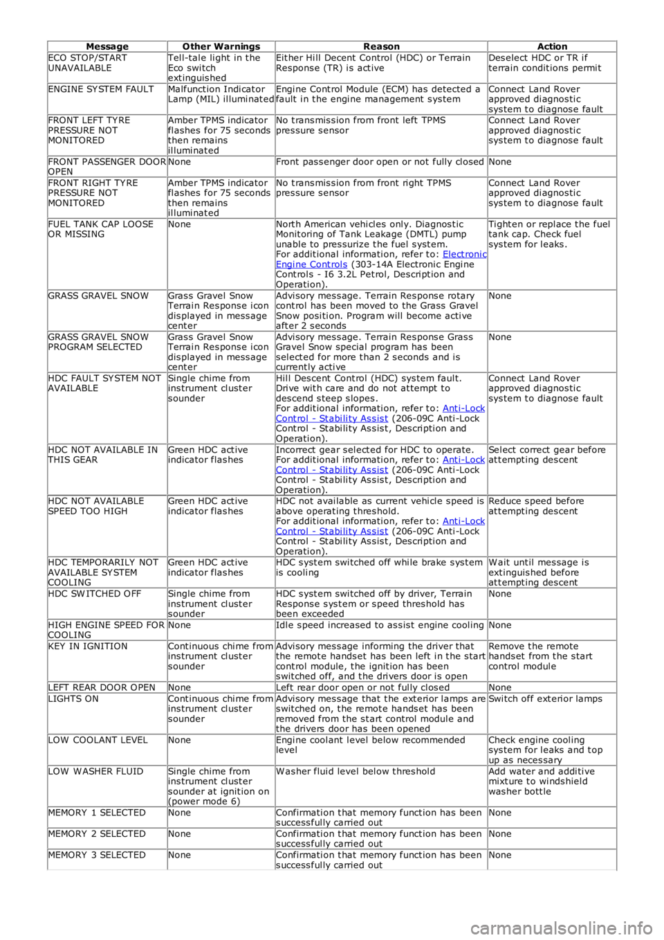
ECO STOP/STARTUNAVAILABLETel l-tal e li ght in t heEco swi tchext inguis hed
Eit her Hi ll Decent Control (HDC) or TerrainRespons e (TR) i s act iveDes elect HDC or TR i fterrain condit ions permi t
ENGINE SY STEM FAULTMalfunct ion Indi cat orLamp (MIL) il lumi nat edEngi ne Cont rol Module (ECM) has detected afault i n t he engi ne management s ys temConnect Land Roverapproved di agnos ti csys tem t o diagnos e faultFRONT LEFT TY REPRESSURE NOTMONITORED
Amber TPMS indicatorfl ashes for 75 secondsthen remainsil lumi nat ed
No t rans mis s ion from front left TPMSpres sure s ensorConnect Land Roverapproved di agnos ti csys tem t o diagnos e fault
FRONT PASSENGER DOOROPENNoneFront pas s enger door open or not fully cl osedNone
FRONT RIGHT TY REPRESSURE NOTMONITORED
Amber TPMS indicatorfl ashes for 75 secondsthen remainsil lumi nat ed
No t rans mis s ion from front ri ght TPMSpres sure s ensorConnect Land Roverapproved di agnos ti csys tem t o diagnos e fault
FUEL TANK CAP LOOSEOR MISSINGNoneNort h American vehi cl es onl y. Diagnos t icMonit oring of Tank Leakage (DMTL) pumpunabl e to pres surize t he fuel s yst em.For addit ional informati on, refer t o: Elect roni cEngi ne Cont rol s (303-14A Electroni c Engi neCont rol s - I6 3.2L Pet rol, Des cri pt ion andOperati on).
Ti ght en or repl ace t he fueltank cap. Check fuelsys tem for l eaks .
GRASS GRAVEL SNOWGras s Gravel SnowTerrai n Res pons e i condis played in mess agecent er
Advi sory mes s age. Terrain Res pons e rotarycont rol has been moved to the Grass GravelSnow posi ti on. Program will become acti veaft er 2 s econds
None
GRASS GRAVEL SNOWPROGRAM SELECTEDGras s Gravel SnowTerrai n Res pons e i condis played in mess agecent er
Advi sory mes s age. Terrain Res pons e Gras sGravel Snow special program has beens el ect ed for more t han 2 s econds and i scurrent ly acti ve
None
HDC FAULT SY STEM NOTAVAILABLESingle chime fromins trument cl ust ers ounder
Hil l Des cent Cont rol (HDC) sys tem faul t.Dri ve wit h care and do not at tempt t odes cend s teep s lopes .For addit ional informati on, refer t o: Ant i-LockCont rol - St abi li ty As s is t (206-09C Anti -LockCont rol - St abi li ty As s is t , Des cri pti on andOperati on).
Connect Land Roverapproved di agnos ti csys tem t o diagnos e fault
HDC NOT AVAILABLE INTHIS GEARGreen HDC act iveindicator flas hesIncorrect gear s el ect ed for HDC to operate.For addit ional informati on, refer t o: Ant i-LockCont rol - St abi li ty As s is t (206-09C Anti -LockCont rol - St abi li ty As s is t , Des cri pti on andOperati on).
Sel ect correct gear beforeat t empt ing des cent
HDC NOT AVAILABLESPEED TOO HIGHGreen HDC act iveindicator flas hesHDC not avai lable as current vehi cl e s peed isabove operat ing t hres hold.For addit ional informati on, refer t o: Ant i-LockCont rol - St abi li ty As s is t (206-09C Anti -LockCont rol - St abi li ty As s is t , Des cri pti on andOperati on).
Reduce s peed beforeat t empt ing des cent
HDC TEMPORARILY NOTAVAILABLE SY STEMCOOLING
Green HDC act iveindicator flas hesHDC s yst em swi tched off whi le brake s ys t emis cooli ngW ait unt il mes sage i sext inguis hed beforeat t empt ing des cent
HDC SW ITCHED O FFSingle chime fromins trument cl ust ers ounder
HDC s yst em swi tched off by driver, TerrainRespons e s ys t em or s peed thres hold hasbeen exceeded
None
HIGH ENGINE SPEED FORCOOLINGNoneIdl e s peed increased to as s is t engine cool ingNone
KEY IN IGNITIONCont inuous chi me fromins trument cl ust ers ounder
Advi sory mes s age informing the driver thatthe remot e hands et has been left i n t he s tartcont rol module, t he ignit ion has beens wit ched off, and t he dri vers door i s open
Remove t he remotehands et from t he s tartcontrol modul e
LEFT REAR DOOR O PENNoneLeft rear door open or not ful ly cl os edNone
LIGHTS ONCont inuous chi me fromins trument cl ust ers ounder
Advi sory mes s age that t he ext eri or l amps ares wit ched on, t he remot e hands et has beenremoved from the s t art control modul e andthe drivers door has been opened
Swi tch off ext eri or lamps
LOW COOLANT LEVELNoneEngi ne cool ant l evel below recommendedlevelCheck engine cool ingsys tem for l eaks and t opup as neces sary
LOW W ASHER FLUIDSingle chime fromins trument cl ust ers ounder at ignit ion on(power mode 6)
W as her flui d level bel ow t hres hol dAdd water and addi ti vemixt ure t o wi nds hiel dwas her bott le
MEMORY 1 SELECTEDNoneConfirmati on t hat memory funct ion has beens uccess ful ly carried outNone
MEMORY 2 SELECTEDNoneConfirmati on t hat memory funct ion has beens uccess ful ly carried outNone
MEMORY 3 SELECTEDNoneConfirmati on t hat memory funct ion has beens uccess ful ly carried outNone
Page 1811 of 3229
Publi s hed: 11-May-2011
Battery and Charging System - General Information -
Vehicle Jump (Emergency) Starting - Using another vehicle
• W ARNINGS:
During normal us e, bat t eries emi t expl osi ve hydrogen gas suffi ci ent t o cause severe expl os i ons and capabl e ofcaus ing serious injury - keep s parks and naked li ght s away from the engine compart ment.
DO NOT at tempt t o s tart the di s abl ed vehi cl e i f it is sus pect ed t hat t he elect rolyte in the bat tery is frozen.
Suit able eye prot ect ion must be worn when working i n t he vicinit y of t he bat t ery.
Take care when working near rot at ing parts of t he engine.
Prior to att empti ng to st art t he dis abled vehicle, ens ure t hat the parki ng brake i s appl ied or s uit abl y chock t hewheels . Ens ure that 'P' - PARK - Aut omati c Trans mis s ion or NEUTRAL - Manual Trans mi ss i on is s elect ed.
• CAUTIO NS:
Ens ure t hat al l electrical l oads are s wi tched OFF pri or to connect ing boos ter cabl es and dis connect boos t er cablespri or to us ing el ect ri cal equipment .
Ens ure t hat the bat tery of the DO NOR vehicle is of 12 volt capaci ty and that all electrical loads on t he dis abl edvehi cl e are s wit ched O FF prior t o connecti ng boost er cables .
Ens ure t hat there is no phys ical contact between t he donor and di sabl ed vehi cl es other than t he boost er cabl es .
• NOTE: Disconnect battery: If t he remote control hands et is not functi oning, it wi ll be neces s ary t o manuall y unlock thevehi cl e us ing t he key.
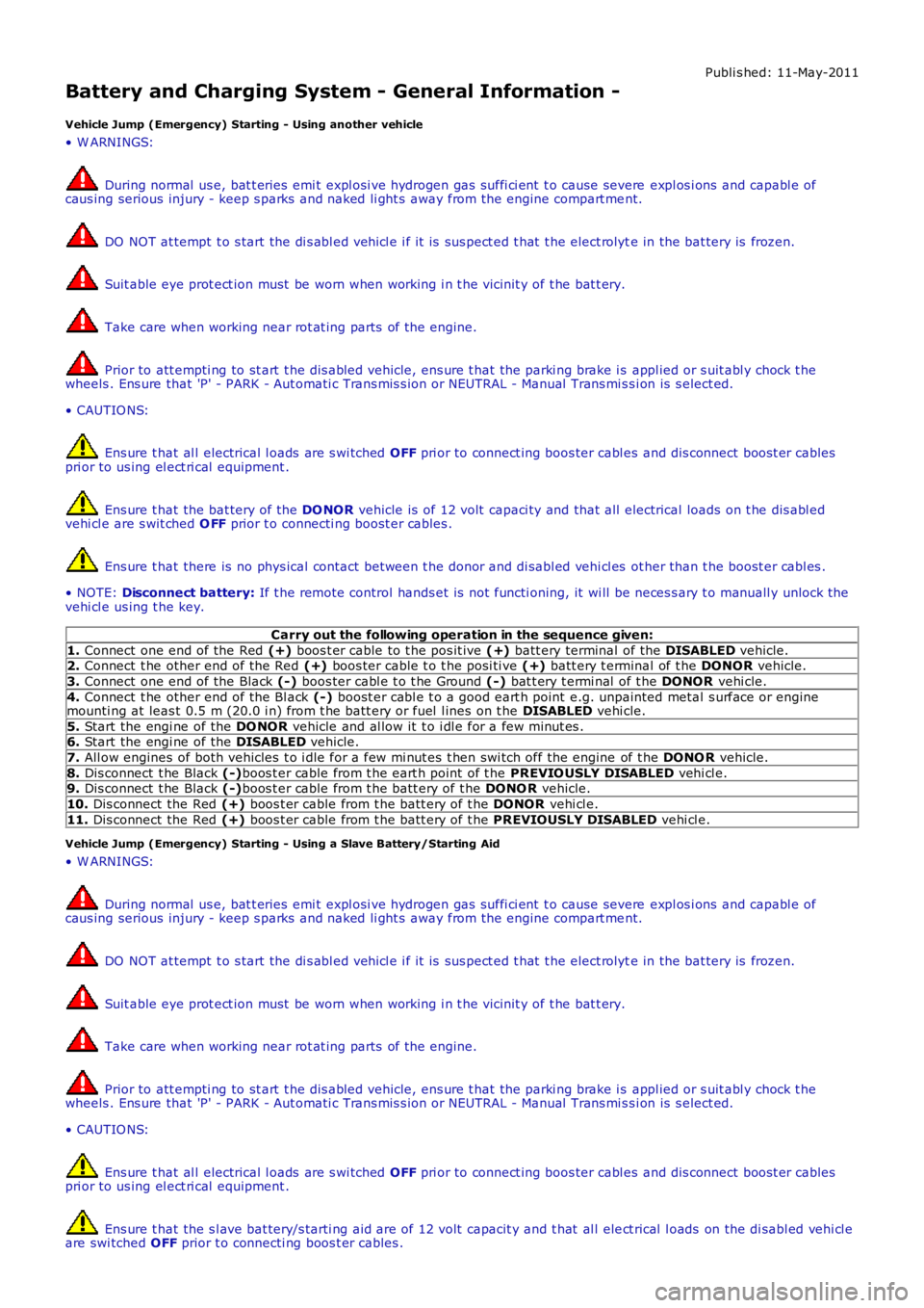
Carry out the following operation in the sequence given:
1. Connect one end of the Red (+) boos t er cable to t he pos it ive (+) batt ery terminal of the DISABLED vehicle.2. Connect t he other end of the Red (+) boos ter cable t o t he posi ti ve (+) batt ery t erminal of t he DONOR vehicle.
3. Connect one end of the Black (-) boos ter cabl e t o t he Ground (-) bat t ery t ermi nal of t he DONOR vehi cle.
4. Connect t he other end of the Bl ack (-) boost er cabl e t o a good eart h point e.g. unpainted metal s urface or enginemounti ng at leas t 0.5 m (20.0 i n) from t he batt ery or fuel l ines on t he DISABLED vehi cle.
5. Start the engi ne of the DO NOR vehicle and al low it t o i dl e for a few minut es .6. Start the engi ne of the DISABLED vehicle.
7. All ow engines of both vehicles t o i dle for a few mi nut es t hen swi tch off the engine of t he DONO R vehicle.
8. Dis connect t he Black (-)boos t er cable from t he eart h point of t he PREVIO USLY DISABLED vehi cl e.9. Dis connect t he Black (-)boos t er cable from t he batt ery of t he DONO R vehicle.
10. Dis connect the Red (+) boos t er cable from t he batt ery of t he DONOR vehi cl e.
11. Dis connect the Red (+) boos t er cable from t he batt ery of t he PREVIOUSLY DISABLED vehi cl e.
Vehicle Jump (Emergency) Starting - Using a Slave Battery/Starting Aid
• W ARNINGS:
During normal us e, bat t eries emi t expl osi ve hydrogen gas suffi ci ent t o cause severe expl os i ons and capabl e ofcaus ing serious injury - keep s parks and naked li ght s away from the engine compart ment.
DO NOT at tempt t o s tart the di s abl ed vehi cl e i f it is sus pect ed t hat t he elect rolyte in the bat tery is frozen.
Suit able eye prot ect ion must be worn when working i n t he vicinit y of t he bat t ery.
Take care when working near rot at ing parts of t he engine.
Prior to att empti ng to st art t he dis abled vehicle, ens ure t hat the parki ng brake i s appl ied or s uit abl y chock t hewheels . Ens ure that 'P' - PARK - Aut omati c Trans mis s ion or NEUTRAL - Manual Trans mi ss i on is s elect ed.
• CAUTIO NS:
Ens ure t hat al l electrical l oads are s wi tched OFF pri or to connect ing boos ter cabl es and dis connect boos t er cablespri or to us ing el ect ri cal equipment .
Ens ure t hat the s l ave bat tery/s tarti ng aid are of 12 volt capacit y and t hat al l elect rical l oads on the di sabl ed vehi cl eare swi tched OFF prior t o connecti ng boos t er cables .
Page 2059 of 3229
The pass i ve ant i-theft sys t em us es the foll owing component s:
Remote hands et trans ponderCJBECMStart cont rol moduleIns t rument clus terABS moduleElectric s t eering column lock (if enabl ed).
• NOTE: On North Ameri can Specificat ion (NAS) vehi cles , a running change was int roduced during 2008 Model Y ear (MY ) t odis able t he electric st eering col umn lock. Under t he change, the i nternal elect ronics (print ed circuit board (PCB), motor,etc.) of t he l ock have been removed and t he lock has been dis abled i n t he car configurat ion fi le. The change i sincorporat ed on VIN (vehi cl e identi fi cat ion number) 082896, 085531, 085622, 085685, 085832, 085891, 085942, 085987,086049, 086081, 086123, 086178, 086276, 086287, 086309, 086363, 086383, 086389, 086398, 086403 and 091770onwards .
The s ys t em i s automat ic and requi res no input from t he dri ver. The engi ne management s yst em wil l onl y allow engi necrank when an aut horizati on data mess age is received from t he CJB. The engi ne st art s ys tem is init iat ed when thes tart/s top s wi tch and t he brake pedal (automat ic t rans mis s ion) or t he cl utch pedal (manual trans mi ss i on) are pres s eds imul taneous l y.
The engi ne management s ys tem (ECM) wi ll only al low engi ne crank, s park (petrol models only) and inject or funct ions whent he foll owing condit ions are met:
A hardwi red Park/Neutral si gnal i s received from the Trans mi ss i on Cont rol Module (TCM) (aut omati c t ransmis s iononly)A hardwi red ignit ion s ignal is recei ved from t he CJBA hardwi red crank reques t s ignal is recei ved from t he CJBEncrypt ed data exchange bet ween t he ins trument cl ust er and the ECM is verifi ed.
Before the CJB will s end t he hardwired igni ti on si gnal , it mus t s ati s factori ly complet e t he fol lowi ng:
Exchanged encrypt ed data wit h the st art control modul e t o validat e t he remot e hands et .
Addit ional ly, before the CJB will s end t he hardwired crank reques t s ignal i t mus t receive t he fol lowing si gnal s:
Brake s ignal from t he brake s wi tch (automat ic t rans mis s ion) or clutch s i gnal from the clut ch s wit ch (manualt ransmis s ion)Hardwi red t rans mis s ion in Park (P) s ignal from t he s elector lever ass embl y (aut omatic trans mi s si on only).
CONTROL DIAGRAM
• NOTE: A = Hardwi red; D = High speed CAN bus ; N = Medium s peed CAN bus ; O = LIN bus ; W = LF t rans mis s ion