2006 LAND ROVER FRELANDER 2 odometer
[x] Cancel search: odometerPage 113 of 3229

Publi s hed: 03-May-2011
General Information - Diagnostic Trouble Code (DTC) IndexDTC:
Instrument Cluster (IPC)
Des cript ion and Operat ion
• NOTE: If a cont rol module or component i s s uspect and the vehicl e remai ns under manufacturer warrant y, refer t o t heW arranty Pol icy and Procedures manual (s ect ion B1.2), or determine i f any pri or approval program is i n operat ion, beforet he replacement of a component.
• NOTE: Generic scan t ool s may not read the codes li st ed, or may read only 5-digi t codes . Match t he 5 digi ts from t he s cant ool t o t he fi rs t 5 di gi ts of the 7-digit code li s ted t o i dent ify the fault (the last 2 digi ts gi ve ext ra informati on read by themanufacturer-approved di agnos ti c s ys t em).
• NOTE: W hen performing volt age or res is t ance t est s , always use a digi tal mult imeter (DMM) accurat e t o t hree deci malplaces, and wi th an up-t o-date cal ibrat ion cert ificate. W hen tes ti ng res is t ance al ways take t he res is t ance of t he DMMleads i nt o account .
• NOTE: Check and recti fy bas ic faul ts before beginni ng diagnos t ic rout ines i nvol vi ng pinpoint t es t s.
• NOTE: Ins pect connect ors for s igns of water ingres s , and pins for damage and/or corros ion.
• NOTE: If DTCs are recorded and, aft er performi ng the pi npoi nt tes ts , a fault is not present , an int ermi tt ent concern maybe t he caus e. Always check for loose connect ions and corroded terminals .
Des cript ion And Operat ion
For a detail ed descripti on of the ins trument cl us t er sys tem, refer t o t he rel evant Descripti on and Operat ion s ecti on in t heworks hop manual .For addit ional informat ion, refer t o: Ins t rument Clus ter (413-01 Inst rument Cl us t er, Des cript ion and Operat ion).
Instrument cluster control module (IPC )DT CDescriptionPossible CauseAction
B1184-62Steering Column LockOutputSignal compare fai lureCheck st eering lock power from CJB. Check CJB forDTCs and refer to relevant DTC Index.For addi ti onal informat ion, refer t o:Communicati ons Network (418-00 Modul eCommunicati ons Network, Di agnos is and Tes t ing).
B1A14-96RCM W arning LampLight Emit t ing Di ode (LED)fai lureIns t all a new ins trument cl us t er.For addi ti onal informat ion, refer t o: Ins t rumentClus t er (413-01 Inst rument Cl us t er, Removal andIns t allat ion).Refer t o t he new module/component ins tall ati onnote at the t op of the DTC Index
B1A84-41Car Configurat ion Dat aFlas h download checks umerrorIns t all lat est avail abl e l evel of software us ing t hemanufacturer approved di agnos ti c s ys t em
B1A84-81Car Configurat ion Dat aInvali d Car Configurat iondata recei vedCheck/amend Car Configurat ion Fil e us ingmanufacturer approved di agnos ti c s ys t em
C2002-62Odometer TamperedDTC s et when one or mores tored odomet er val ue doesnot match
Clear DTC, cycle ignit ion and re-t est
U0010-87Medium Speed CANCommunicati on BusMult ipl e los s of CAN dat a toother s yst emsCarry out pinpoint tes t s ass ociat ed wit h t his DTCus ing t he manufacturer approved diagnos ti cs yst em
U0010-88Medium Speed CANCommunicati on BusBreak i n connecti on to busCarry out pinpoint tes t s ass ociat ed wit h t his DTCus ing t he manufacturer approved diagnos ti cs yst emU0140-08Lost Communi cat ionW i th Body Cont rolModule
No mes s ages recei ved fromCJB for great er than t imeoutperi od
Carry out pinpoint tes t s ass ociat ed wit h t his DTCus ing t he manufacturer approved diagnos ti cs yst em
U0208-08Lost Communi cat ionW i th "Seat Cont rolModule A"
No mes s ages recei ved fromDSM for greater t hant imeout period
Check DSM for DTCs and refer t o rel evant DTCIndex.For addi ti onal informat ion, refer t o: Seat s (501-10Seati ng, Di agnos is and Tes ti ng).Carry out CAN Net work i nt egri ty t es ts us ing themanufacturer approved di agnos ti c s ys t emU0300-62Int ernal Cont rol ModuleSoft ware Incompat ibi lit yConfigurat ion dat a receivedis di fferent from the s t oreddata
Check correct ins trument cl us t er is i nst all ed
U3000-46Control ModuleEEPROM writ e errorCheck power and ground circui ts to the i nst rumentclus ter, cl ear DTC and re-tes t. If DTC remains ,ins t al l a new i nst rument clus t er.For addi ti onal informat ion, refer t o: Ins t rumentClus t er (413-01 Inst rument Cl us t er, Removal andIns t allat ion).Refer t o t he new module/component ins tall ati onnote at the t op of the DTC Index
Page 1771 of 3229
Vehicle i n power mode 6 (all vehi cles except NAS vehicles )Vehicle i n power mode 6 for 75 s econds (NAS vehicl es onl y)Vehicle s peed is greater t han 6 mph (10 kph)Dri vers s afet y belt not s ecured in i ts buckleLarge pas senger det ect ed i n front pas s enger s eat wit h an uns ecured safety bel t.
The warni ng indicator wi ll flas h at a frequency of 2 Hz while accompani ed by a chime from the i nst rument clus ter for 10s econds. Thi s is foll owed by a 10 s econd period where the warning i ndicat or is permanent ly ill uminat ed and the s ounder i ss il ent . Thi s 10 s econd cycle wi ll be repeat ed for a maxi mum of 190 seconds or any of t he condit ions l is t ed above cease toexis t.
Supplemental Restraint System Warning Indicator
The Suppl ement al Rest rai nt Sys tem (SRS) warning i ndi cat or is i lluminated on recei pt of a medium s peed CAN bus si gnalfrom the CJB. The si gnal originat es in t he RCM whi ch monit ors t he condi ti on of the SRS and ill uminat es the red warni ngindicat or accordingly.
The SRS warni ng indicator i s il lumi nat ed by t he RCM for a 6 s econd bul b check when the vehicle firs t ent ers power mode 6.If a fault is detect ed wit h t he indicator, the ins trument cl us t er returns a medi um speed CAN bus s ignal vi a t he CJB to theRCM and a Diagnos t ic Troubl e Code (DTC) i s s tored in the RCM's memory. The mes s age 'SrS' wi ll als o be di spl ayed i n t heodometer.For addit ional informat ion, refer t o: Informat ion and Mes s age Cent er (413-08 Informat ion and Mes s age Cent er, Des cript ionand Operat ion).
Left and Right Hand Turn Signal Indicators
The green l eft and right hand turn s ignal i ndicat ors are i ll uminated on recei pt of medium speed CAN bus s i gnals from t heCJB. The CJB provi des a CAN bus s ignal wit h one of t he foll owing values :
0 - LH st eeri ng col umn mul ti -funct ion s wit ch in the central pos it ion1 - LH st eeri ng col umn mul ti -funct ion s wit ch in the LH turn posi ti on2 - LH st eeri ng col umn mul ti -funct ion s wit ch in the RH turn pos it ion3 - Hazard fl as hers reques t ed.
If the vehicle is i n power mode 6 t he ins trument cl ust er wil l fl as h the appropri ate turn s ignal i ndicat or if a medium speedCAN bus s ignal is recei ved wit h a value of 1 or 2. Medi um s peed CAN bus s ignals wi th a value of 3 wi ll acti vat e both theLH and RH turn s ignal i ndicat ors si mult aneous ly i rrespecti ve of power mode.
W hen acti vat ed, the l eft and right hand turn s ignal indicators wil l be accompanied by 'ti ck t ock' chimes from t he ins trumentclus ter s ounder.
Brake Warning Indicator
EBA and EBD warnings are trans mi tt ed t o t he CJB from t he ABS module over t he high s peed CAN bus . Thes e s ignals arerel ayed t o t he i ns t rument clus ter on t he medium s peed CAN bus and wil l act ivate the brake warning i ndicat or when t hevehi cl e i s in power mode 6. If an EBA warni ng is request ed, the i ndi cat or wil l ill uminat e in an amber color. If an EBDwarni ng is reques t ed, t he indi cat or will i ll uminate in a red color.
Low brake flui d level warnings are als o t rans mit t ed to the i nst rument clus t er from the CJB on the medi um s peed CAN bus .The s ignal origi nat es in the ABS modul e which recei ves a hardwired input from the brake flui d level s ens or. If a l ow brakefl uid warning i s reques ted, the indicator wil l il lumi nat e i n a red col or when the vehicle is i n power mode 6.
The brake warni ng indi cat or i s als o s ubject t o a 3 second bul b check when the vehicle firs t ent ers power mode 6. Theindicat or wi ll i lluminate in a amber color for 1.5 s econds t hen a red col or for 1.5 s econds .
High Eng ine Coolant Temperature Warning Ind icator
The red hi gh Engine Coolant Temperature (ECT) warning i ndi cat or is control led by the engine t emperat ure gage s oft ware(see above).
Headlamp High Beam Indicator
The blue headlamp hi gh beam i ndi cat or is i ll uminated on recei pt of a medium s peed CAN bus si gnal from the CJB. Thes ignal origi nat es in the l ight s wit ch module and i s t ransmit ted t o t he CJB over t he LIN bus. The i nst rument clus t er will onlyil lumi nat e t he headl amp high beam indicator when t he vehicle i s in power mode 6 and t he LH s teeri ng column mul ti -functi on s wit ch is moved t o t he high beam pos i ti on.
Tire Pressure Monitoring System Indicator
The Tire Pres s ure Moni tori ng Syst em (TPMS) indicator i s cont rol led by t he ins t rument clus ter on receipt of medium s peedCAN bus s ignals from t he CJB. The s ignal ori gi nates i n t he TPMS module. The indicator i s il lumi nat ed in an amber col or fora 3 second bulb check by the TPMS modul e when t he vehi cl e enters power mode 6. If t he indicator remains i lluminated orfl ashes after t he engi ne is st art ed or when dri vi ng, the TPMS has developed a faul t. The t ire pres s ures s houl d bemonit ored manuall y unti l the fault is recti fi ed.For addit ional informat ion, refer t o: W heels and Ti res (204-04 W heels and Tires , Des cript ion and Operat ion).
Anti-lock Brake System Warning Indicator
The Anti -l ock Brake Sys t em (ABS) warning i ndicat or is controll ed by the ABS module whi ch trans mi ts a high s peed CAN busmes s age to t he CJB. The CJB relays t he mes sage t o t he i ns t rument clus ter over the medi um s peed CAN bus . The warningindicat or i s il lumi nat ed i n an amber col or for 3 s econds for a bulb check by the ABS modul e when t he vehi cl e enters powermode 6. If the warning i ndi cat or remains ill uminat ed or ill uminat es when drivi ng, an ABS fault has occurred and t he ABSfuncti on wil l not be avai lable.
Duri ng the bul b check, if t he warni ng indicator comes on for 0.5 s econd, t hen goes off for 0.5 second and is then
Page 1794 of 3229
MessageO ther WarningsReasonAction
Descripti on and Operat ion).
AUXILIARY HEATERUNAVAILABLE LOW FUEL(vehi cl es from 2009MYwi th Fuel Fired Boos t erHeater (FFBH))
NoneFuel l evel in fuel tank i s at or bel owthreshold when FFBH 'ON' reques t is made.Repl eni sh fuel in fuel tank
AUXILIARY HEATERUNAVAILABLE LOWBATTERY (Vehicles from2009MY wit h FFBH)
NoneBatt ery volt age is bel ow t hres hol d whenFFBH 'ON' reques t is made.Invest igat e reas on for l owbat tery volt age. Follow theprocedures i n t he Batt eryCare Manual t o es t abl is hthe condi ti on of thebat tery.
TRIP COMPUTER
Tri p comput er informat ion i s s hown in t he bott om hal f of the mes s age cent er when the s creen i s in dis play mode 3.
Trip Meter
A microprocess or in the ins trument cl us t er calculat es the trip dat a based on a wheel speed s ignal broadcas t by t heAnti -l ock Brake Sys t em (ABS) modul e over the hi gh speed CAN bus . The CJB act s as a gat eway and t ransmit s t he wheels peed si gnal t o t he ins trument cl ust er over t he medium s peed CAN bus .
The t rip meter di spl ays t he dis t ance t he vehicle has t raveled s i nce t he l as t t ri p met er res et . The t ri p met er can be reset bypres s ing and holdi ng the t rip computer butt on for more t han 1 s econd. The t ri p met er can dis play up to a dis t ance of 999.9mi les or kil omet ers . W hen this fi gure is exceeded the t ri p met er st art s again from 0 miles or ki lometers .
The t rip dat a i s s tored in the i nst rument clus t er Random Acces s Memory (RAM) and will be los t if t he batt ery i sdis connected.
Average Fuel Consumption
The ins t rument clus ter receives 2 fuel t ank level readings on t he medium s peed CAN bus vi a t he CJB. The i nst rumentclus ter calcul ates an average value of t he amount of usable fuel in the t ank from t he 2 s i gnal s. Every 200 meters ofvehi cl e t ravel the i nst rument clus t er re-calculat es this val ue to det ermine how much fuel has been us ed. Thi s value i s thenaveraged over t he las t 31 mi les (50 kil ometers ) of t ravel and di s pl ayed in t he t ri p comput er.
The dis t ance t raveled s ignal ori gi nates i n t he ABS module and i s received by t he inst rument clus ter over t he medi ums peed CAN bus via t he CJB.
Range
The range value i s calculated us i ng the average fuel cons umpt ion val ue (s ee above) and t he fuel t ank level val ue. Bydividi ng the fuel tank l evel val ue by t he average fuel cons umpti on value t he ins t rument clus ter can cal cul at e t he dis t ancet he vehi cl e can travel wi th the current amount of us abl e fuel i n t he tank before refil li ng is necess ary.
Average Speed
The average s peed s i gnal is cal cul at ed us ing t he vehi cle s peed s ignal s uppli ed by the CJB over the medium speed CANbus. This si gnal originat es in t he ABS module and is an average of t he 4 wheel s peed si gnal s. This val ue is di vided by t het ime si nce the l ast t ri p computer res et t o cal cul ate the average vehicle s peed.
ODOMETER
The odometer is locat ed i n the speedometer and dis plays t he tot al di s tance the vehicl e has travel ed. This is calculat edus ing t he s ame s ignal as that us ed for t he trip meter.
The odometer dis play can s how 6 characters and dis t ances up t o 999,999 mi les or kil ometers . The value i s s tored in aprot ect ed area of t he ins t rument clus ters Electroni cal ly Eras able Programmabl e Read Only Memory (EEPROM) every 1.2mi les (2 kil ometers ) of vehicle t ravel. W hen the i gnit ion i s s wit ched off, back up odomet er val ues are al so s tored in t hefol lowing modul es:
CJBABS moduleECMRest rai nts Cont rol Modul e (RCM)Dri ver door modulePass enger door module.
The odometer values in thes e modules are s ent t o t he ins t rument clus ter over t he medi um s peed CAN bus wit hin the firs t2 s econds of t he vehi cl e entering power mode 6. If the values received are t he s ame, t he clus ter det ermi nes t he odometervalue has not been tampered wit h. If any value i s outs ide of a 186 mil e (300 ki lometer) wi ndow the i nst rument clus t ers tores a Diagnos ti c Trouble Code (DTC) and wil l di spl ay the majori ty val ue. The DTC can be ret rieved us ing t he Land Roverapproved diagnos t ic s yst em.
Vehicle Operating Modes
The vehi cl e has 4 operat ing modes , which al low cert ain features to be enabl ed and dis abl ed:
Normal (nor)Fact ory (fact )Trans port (trans p)Cras h (cras h)
Page 1795 of 3229
The current vehicle operat ing mode, s hown in parenthes is above, i s dis played in the odomet er for 5 s econds when t hevehi cl e first ent ers power mode 6.
• NOTE: 'Nor' is only di s pl ayed in t he Odometer when t he vehicle operat ing mode is changed t o normal from any of theother vehi cle operat ing modes . Under al l ot her condit ions , 'Nor' is not di spl ayed.
The vehi cl e operat ing mode can be changed us i ng the Land Rover approved di agnos ti c sys t em.
Gear Position
The gear pos it ion i ndicat or s hows the current aut omati c t ransmis s ion s elector l ever posi ti on. During normal operat ion thedis play wi ll s how P (park), R (revers e), N (neutral) and D (drive). W hen the t rans mis s ion is operat ed in 'CommandShi ft ™'mode, the odomet er di spl ays the current ly sel ect ed manual gear; 1, 2, 3, 4, 5 or 6.
In the event of eit her a CAN bus fai lure, or if t he TCM det ect s a t rans mi ss i on overheat s it uati on, t he odometer wi ll dis playt he let ter 'E' in the s ame area of t he dis play as t he 'CommandShift™' s elected gear informat ion.
Supplemental Restrain System Warning Indicator
If the i nst rument clus ter det ect s the Supplement al Res t raint Sys tem (SRS) warni ng indicator has fai led, t he mes sage 'SrS'wil l be dis played in the odomet er and a DTC s tored. The DTC can be ret rieved from the ins trument cl us t er us i ng the LandRover approved diagnost ic sys tem.
Service Interval Indicator
The Service Interval Indi cat or (SII) i nforms t he driver when t he next vehicle servi ce is due. The ins t rument clus ter monit orst he dis tance t he vehi cl e has travel ed and t he ti me el aps ed s ince t he las t s ervice.
If vehicle dis tance is the t rigger for the SII, 'SERVICE' will be di s pl ayed in t he odometer accompanied by a dis tancequal ifier (ei ther 'MILES' or 'KM' dependi ng on t he ins trument cl ust er s pecificati on). A di st ance counter wi ll als o be di s pl ayedin the t op Ri ght Hand (RH) corner of t he odometer. If t he point at which a servi ce is requi red is pas sed, t he count er wi lldis play a negat ive value. W hen acti vat ed, t he SII is di spl ayed for 5 s econds when t he vehi cl e enters power mode 6.
If ti me i s the trigger for the SII, 'SERVICE' wil l be di s pl ayed in t he odometer accompanied by a clock symbol . A count er willals o be di spl ayed i n t he t op RH corner of the odomet er. If t he point at which a s ervice is required is pas s ed, t he count erwil l dis play a negati ve val ue. Agai n, when act ivated t he SII is dis played for 5 s econds when t he vehi cl e enters power mode6.
If bot h t he dis tance and t ime triggers are acti vat ed, t he SII wil l di s pl ay the di s tance informat ion for 5 s econds, foll owedby t he ti me i nformati on for 5 s econds .
W hen a service has been carri ed out , t he SII wi ll need t o be re-s et. This can be done us ing t he Land Rover approveddiagnost ic s ys tem or foll owing a manual re-s et procedure. The manual re-s et mode is ent ered by carrying out the foll owingrout ine:
Pres s and hold the t ri p res et butt on wi th the vehicle st ati onary and in a power mode les s t han 6.W hi le holdi ng the trip res et but ton, enter t he vehi cl e int o power mode 6.Releas e the trip res et but ton wit hi n 10 s econds of entering power mode 6.
If the manual re-set mode has been s ucces s full y entered 'dISt ' or 'DATE' wi ll be di spl ayed i n t he odomet er, dependi ng onwhich t ri gger has been acti vat ed.
To clear the 'dISt ' trigger pres s, and hold the t rip reset but ton for more than 5 s econds wit hi n 10 s econds of entering t hemanual re-s et mode. If s ucces s ful, 'RESET' wil l be dis played in the odometer for 5 seconds. If t he dat e t ri gger has notbeen act ivated 'END' wil l t hen be dis played i n t he odomet er.
• NOTE: The dis t ance t ri gger wi ll not res et if t he dis t ance t he vehi cle has t raveled i s les s t han 20% of t he next s ervi ceint erval val ue.
If the dat e trigger has been act ivated, 'DATE' wil l be dis played in t he odometer. To clear the t ri gger, pres s and hold t het rip res et but t on for more t han 5 s econds wit hin 10 s econds of 'DATE' being di s pl ayed. If succes s ful , 'RESET' wi ll bedis played wit hin the odomet er for 5 s econds fol lowed by 'END'. The odomet er wil l now exit re-s et mode.
AMBIENT AIR TEMPERATURE
The ins t rument clus ter can dis play t he ambient air t emperature readi ng in ei ther degrees Cels ius or Fahrenhei t. Theambient air t emperat ure s ignal ori gi nat es i n the ambient air t emperature s ens or. The s ens or i s a Negati ve TemperatureCoefficient (NTC) t hermi st or, and i s mounted i n t he LH door mirror. A t emperature value i s cal cul ated by t he ECM andbroadcas t over the hi gh speed CAN bus to t he i ns t rument clus ter.
If the t emperat ure value fall s bel ow 4ºC (39ºF) t he mes sage center wi ll flas h the low ambi ent ai r temperat ure icon 5t imes . Thi s i s accompanied by a chime from the i nst rument clus t er s ounder. The low ambient air t emperature icon wi ll berepeated if t he ambient air t emperature ri s es above 6ºC (43ºF) t hen drops below 4ºC (39ºF) again or a new ignit ion cycleis st art ed.
Page 2318 of 3229
wi ll double lock the vehicle to dis engage the interior and ext erior handles , and will arm the active and pass ive ant i-t heftsystem. For additi onal informat ion, refer to:
Ant i-Theft - Active (419-01A Anti -Theft - Active, Des cri pti on and Operation),Ant i-Theft - Pass ive (419-01 Ant i-Theft - Pass ive, Description and Operat ion).
Central Locking System - Automatic Modes
The central locking s ys tem feat ures automat ic modes to control t he vehicl e entry points , and provi de prot ection for t hesystem components.
The central locking s ys tem incorporates the fol lowing automati c modes:
Misl ock modeSpeed dependant locking mode (i f programmed)Cras h unlocki ng modeRepeti tion bl ocking modeLockout protect ion modeAutomat ic relock mode (if programmed)Transport mode.
Mislock Mode
A mi slock occurs i f t he CJB receives an ext ernal lock or double lock reques t when a hi nged panel is ajar. To indicat e ami slock t he CJB sounds t he horns to produce a 100 milli second 'chirp'.
If a mi slock occurs due t o an external lock reques t when a hinged panel is ajar, t he CJB will not carry out a lock reques t onany acces s points .
Speed Dependant Locking Mode
W hen speed dependant l ocking is enabled the CJB wil l i nt ernal ly lock al l t he doors when t he vehicl e speed exceeds 8 km/h(5 mph) wit h al l the doors closed and the engine running. If the dri ver or front passenger door is opened and then cl os ed,when t he vehicl e s lows down or s tops and then increases to more t han 8 km/h (5 mph) again, the CJB wi ll int ernally lock thedoors.
Speed dependant locki ng may be enabled or dis abled by the deal er us ing the Land Rover approved diagnost ic syst em.
Crash Unlocking Mode
W ith the ignit ion in power mode 6 (Ignit ion), if a cras h occurs that tri ggers deployment of t he air bags , t hen t he CJB willunlock al l of t he doors . The CJB is informed of the crash by a s tatus mess age from the Rest raint s Cont rol Modul e (RCM) onthe medi um s peed CAN bus t hat changes from 'no crash' t o 'crash'.
The central locking s ys tem will als o perform crash unl ocking mode i f a 'no cras h' status mes sage is not received from t heRCM every 500 mi llis econds .For addit ional informat ion, refer t o: Ai r Bag and Safet y Belt Pretens ioner Supplement al Rest raint Sys tem (SRS) (501-20BSupplemental Res traint Sys tem, Des cription and Operat ion).
Repetition Blocking Mode
To prot ect the central locki ng s yst em motors and actuat ors against syst em mi s-use, the CJB i ncorporat es repeti tion bl ockingto limi t t he maximum operati ng rate of each mot or and actuator. The lock mot or in each door lat ch also i ncorporat es thermalprotect ion.
Central Locking System Motor and Actuator Operating ParametersMotor orActuatorCurrent On T ime(ms)Maximum Operations (perminute)Nominal Operating Current(A)Stall Current(A)Li ftgat e lat ch600 ± 10103.6 to 5.27.5Fuel fi ller door700 ± 1052.78Door doubl e l ock100 to 110100.281.14Door lock100 to 110100.543.31Lockout Protection Mode
The vehicle is not able to be locked us ing a front door central l ocking butt on or i ns trument panel central l ocking swit ch if anydoor is open.
If an internal lock reques t is recei ved from ei ther of the front door central locking but tons , t he CJB will cent rally lock thevehicle and then centrall y unl ock the vehicle if any door is open.
If a front door i s open and the open door central locki ng butt on i s press ed and held i n t he locked pos it ion, the open frontdoor may remai n i n the l ocked s tate. W hen t he open door is subs equently clos ed, the CJB will centrally unl ock all doors.
Automatic Relock Mode
Automati c rel ock prevent s accidental operation of the remote hands et but tons that will unlock and disarm t he vehicl e.
W hen the central locki ng s yst em is unlocked us ing the remote handset, and a door or l iftgate is not opened or t he remot ehandset is not placed in the s tart cont rol uni t wit hin 1 minut e, the CJB wi ll automatical ly lock or double l ock t he vehicl eagai n, depending on the previous ly locked mode.
Transport Mode
Al l new vehicl es are delivered from the factory in transport mode. Trans port mode replaces the t radit ional t ransi t rel ay andinhibits a number of el ectri cal s ys tems and features t o reduce quiescent drain from the batt ery during delivery. When t hevehicle is in t rans port mode 'trans p' is displayed in the i ns trument clust er odometer. Si ngle point ent ry is enabled and gl oballocki ng and unlocking usi ng t he remot e handset i s dis abled.
Page 2739 of 3229
19
Quick start
R
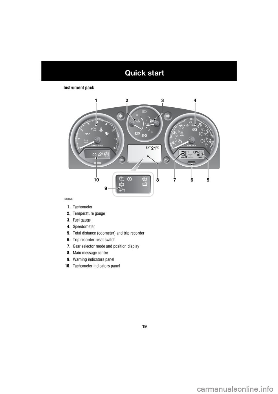
Instrument pack
1. Tachometer
2. Temperature gauge
3. Fuel gauge
4. Speedometer
5. Total distance (odometer) and trip recorder
6. Trip recorder reset switch
7. Gear selector mode and position display
8. Main message centre
9. Warning indicators panel
10. Tachometer indi cators panel
EXT C21
E83375
567108
9
1423
Page 2740 of 3229
20
Quick start
L
Tachometer
Indicates engine spee d in revolutions per
minute (x 1 000). In normal driving conditions
the engine is most fuel efficient between 2 000
and 3 000 rev/min.
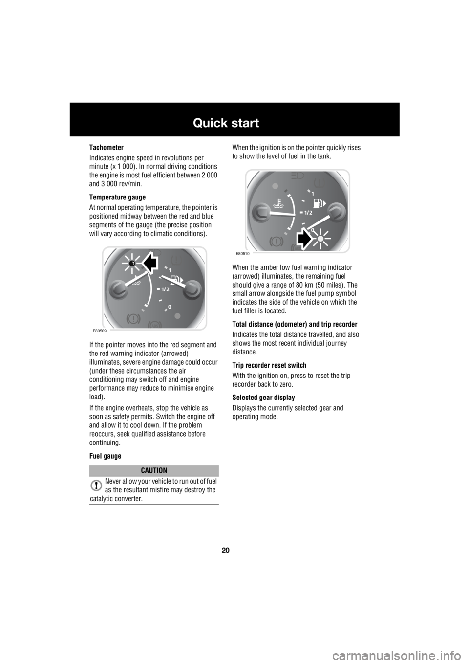
Temperature gauge
At normal operating temperature, the pointer is
positioned midway between the red and blue
segments of the gauge (the precise position
will vary according to climatic conditions).
If the pointer moves into the red segment and
the red warning indicator (arrowed)
illuminates, severe engi ne damage could occur
(under these circumstances the air
conditioning may switch off and engine
performance may reduce to minimise engine
load).
If the engine overheats, stop the vehicle as
soon as safety pe rmits. Switch the engine off
and allow it to cool down. If the problem
reoccurs, seek qualified assistance before
continuing.
Fuel gauge When the ignition is on the pointer quickly rises
to show the level of fuel in the tank.
When the amber low fuel warning indicator
(arrowed) illuminates, the remaining fuel
should give a range of 80 km (50 miles). The
small arrow alongside th e fuel pump symbol
indicates the side of the vehicle on which the
fuel filler is located.
Total distance (odometer) and trip recorder
Indicates the total distance travelled, and also
shows the most recent individual journey
distance.
Trip recorder reset switch
With the ignition on, press to reset the trip
recorder back to zero.
Selected gear display
Displays the currently selected gear and
operating mode.
CAUTION
Never allow your vehicl e to run out of fuel
as the resultant misfire may destroy the
catalytic converter.
E80509
E80510
Page 2817 of 3229
97
Instruments
R
InstrumentsINSTRUMENT PANEL OVERVIEW
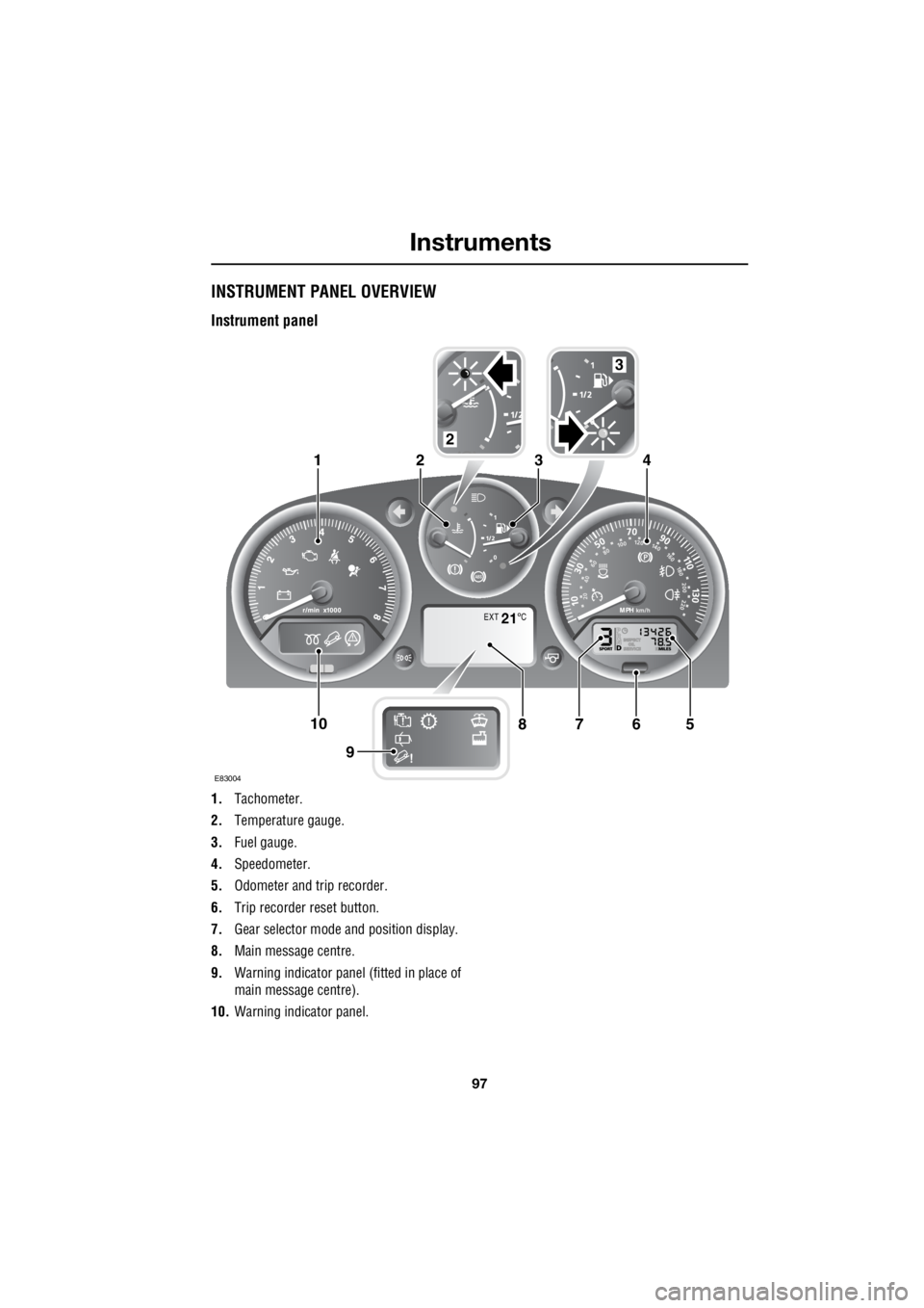
Instrument panel
1. Tachometer.
2. Temperature gauge.
3. Fuel gauge.
4. Speedometer.
5. Odometer and trip recorder.
6. Trip recorder reset button.
7. Gear selector mode and position display.
8. Main message centre.
9. Warning indicator panel (fitted in place of
main message centre).
10. Warning indicator panel.
EXT C21
E83004
567108
9
1423
2
3