2006 LAND ROVER FRELANDER 2 ad blue
[x] Cancel search: ad bluePage 2 of 3229
Important Safety Instructions
Appropri at e s ervi ce methods and correct repai r procedures are es sent ial for t he s afe, rel iable operat ion of al l motor
vehi cl es as well as t he pers onal s afet y of t he individual carryi ng out t he work.
Anyone who departs from t he ins truct ions provi ded in t his manual mus t fi rs t es tabli sh that pers onal s afet y or vehi cle
int egrit y i s not compromis ed by t he choi ce of method, tools or component s .
Warnings, Cautions and Notes in This ManualW ARNING: W arni ngs are us ed t o indicate that fai lure t o fol low a procedure correct ly may res ul t in pers onal injury.CAUTION: Cauti ons are us ed t o indicat e that failure t o fol low a procedure correct ly may res ult in damage to the
vehi cl e or equipment bei ng us ed.
• NOTE: Notes are us ed t o provide addit ional ess enti al i nformati on required to carry out a compl et e and s at is factory
repair.
Generic warnings or caut ions are in their relevant des cript ion and operat ion procedure wit hi n s ect ion 100-00. If t he generic
warni ngs or cauti ons are requi red for a procedure, there wil l be a referral to t he appropri ate des cri pt ion and operat ion
procedure.
If a warni ng, cauti on or not e only appli es to one s tep, it i s placed at the beginni ng of the s peci fi c s tep.
Trustmark Authoring Standards (TAS) Removal and Installation Procedures
• NOTE: TAS s tyl e procedures can be identi fi ed by s teps t hat have no accompanying step t ext and t he magenta color of
t he elect rical connect ors and fast eners s uch as nut s , bol ts , clamps or cli ps.
A TAS removal and i nst all at ion procedure uses a s equence of color i ll us t rat ions t o indicate the order to be foll owed when
removi ng/dis ass embli ng or ins tal li ng/ass embli ng a component .
Many of the TAS procedures will have t he ins tal lat ion i nformat ion wit hi n t he removal s teps . Thes e procedures wi ll have the
fol lowing not e at t he begi nni ng of the procedure:
• NOTE: Removal s t eps in t his procedure may cont ain i nst all ati on det ail s.
Items s uch as O-ri ng s eal s, gas ket s , s eal s, s elf-l ocki ng nut s and bolt s are to be dis carded and new component s ins tal led
unles s otherwis e s tat ed wit hin the procedure. Coated nut s or bol ts are t o be reused, unles s damaged or ot herwi se st ated
wit hin the procedure.
Speci ficat ion procedures wi ll cont ain al l techni cal data that are not part of a repair procedure.
TAS Graphics
Colors used i n t he graphic are as fol lows :
Blue - Indicates t he t arget it em, it em t o be removed/ins t al led or dis as s embl ed/as sembl edGreen and Brown - Indi cat es a s econdary it em t hat needs t o be det ached, removed/ins tal led or
dis as sembl ed/ass embl ed prior t o t he t arget it emMagent a - Indicates elect rical connectors and fas teners such as nut s, bolt s , cl amps or cl ipsPale Bl ue - is for t he special t ool (s ) and general equi pment .There may be mult ipl e s teps as si gned to one ill ust rat ion.
Numbered point ers are us ed to indicate the number of electrical connect ors and fast eners s uch as nuts , bolt s, clamps or
clips .
Items i n t he il lus trati on can be transparent or us e cutouts to show hi dden det ail (s ).
Page 80 of 3229
Publ is hed: 27-Apr-2011
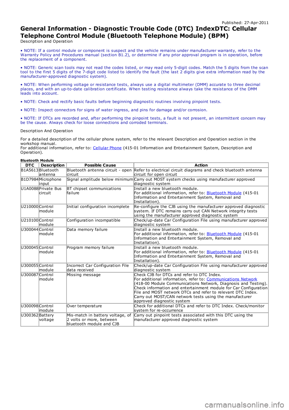
General Information - Diagnostic Trouble Code (DTC) IndexDTC: Cellular
Telephone Control Module (Bluetooth Telephone Module) (BPM)
Des cript ion and Operat ion
• NOTE: If a cont rol module or component i s s uspect and the vehicl e remai ns under manufacturer warrant y, refer t o t heW arranty Pol icy and Procedures manual (s ect ion B1.2), or determine i f any pri or approval program is i n operat ion, beforet he replacement of a component.
• NOTE: Generic scan t ool s may not read the codes li st ed, or may read only 5-digi t codes . Match t he 5 digi ts from t he s cant ool t o t he fi rs t 5 di gi ts of the 7-digit code li s ted t o i dent ify the fault (the last 2 digi ts gi ve ext ra informati on read by themanufacturer-approved di agnos ti c s ys t em).
• NOTE: W hen performing volt age or res is t ance t est s , always use a digi tal mult imeter (DMM) accurat e t o t hree deci malplaces, and wi th an up-t o-date cal ibrat ion cert ificate. W hen tes ti ng res is t ance al ways take t he res is t ance of t he DMMleads i nt o account .
• NOTE: Check and recti fy bas ic faul ts before beginni ng diagnos t ic rout ines i nvol vi ng pinpoint t es t s.
• NOTE: Ins pect connect ors for s igns of water ingres s , and pins for damage and/or corros ion.
• NOTE: If DTCs are recorded and, aft er performi ng the pi npoi nt tes ts , a fault is not present , an int ermi tt ent concern maybe t he caus e. Always check for loose connect ions and corroded terminals .
Des cript ion And Operat ion
For a detail ed descripti on of the cell ular phone sys tem, refer t o t he rel evant Des cript ion and Operat ion s ecti on in theworks hop manual .For addit ional informat ion, refer t o: Cellul ar Phone (415-01 Informat ion and Ent ert ainment Sys t em, Descripti on andOperat ion).
Bluetooth Module
DT CDescriptionPossible CauseAction
B1A5613Bl uet oothant ennaBluetooth ant enna circuit - openci rcuitRefer t o electrical ci rcuit diagrams and check bluet oot h ant ennacircuit for open ci rcuit
B1D7984Mi crophonei nputSi gnal ampl it ude bel ow mi nimumCarry out MOST s yst em checks us ing manufact urer approveddiagnost ic s ys tem
U1A0088Private Buscircui tBT chi pset communicati onsfail ureIns t all a new bl uet ooth modul e.For addit ional informat ion, refer t o: Bluetoot h Module (415-01Informat ion and Ent ert ai nment Sys t em, Removal andIns t allat ion).
U210000Cont rolmodul eInit ial configurat ion incompl eteRe-confi gure t he CJB usi ng the manufact urer approved diagnos t ics ys t em. If DTC remai ns carry out CAN Net work integrit y tes t sus ing t he manufacturer approved diagnost ic sys tem
U210100Cont rolmodul eConfigurat ion i ncompat ibleCheck/up-dat e Car Confi gurati on File usi ng manufacturer approveddiagnost ic s ys tem
U300044Cont rolmodul eDat a memory failureIns t all a new bl uet ooth modul e.For addit ional informat ion, refer t o: Bluetoot h Module (415-01Informat ion and Ent ert ai nment Sys t em, Removal andIns t allat ion).
U300045Cont rolmodul eProgram memory fail ureIns t all a new bl uet ooth modul e.For addit ional informat ion, refer t o: Bluetoot h Module (415-01Informat ion and Ent ert ai nment Sys t em, Removal andIns t allat ion).U300055Cont rolmodul eIncorrect Car Configurat ion Fi ledat a receivedCheck/up-dat e Car Confi gurati on File usi ng manufacturer approveddiagnost ic s ys temU300087Cont rolmodul eMis s ing mes s ageCheck CJB for DTCs and refer t o DTC Index.For addit ional informat ion, refer t o: Communicati ons Net work(418-00 Modul e Communicat ions Network, Di agnos is and Tes t ing).Check i nformati on and ent ert ainment module for Car Configurat ionFil e and MOST network DTCs and refer to relevant DTC Index.Carry out MOST/CAN net work t es ts us ing the manufact urerapproved diagnos t ic s yst em
U300098Cont rolmodul eOver t emperat ureCheck for addi ti onal DTCs and refer to DTC Index. Check/moni tors ys t em for re-occurrenceU300362Bat teryvolt ageMis -match i n batt ery volt age, of2 volt s or more, betweenbl uetooth modul e and CJB
Carry out pinpoi nt tes t s ass ociated wit h t hi s DTC us ing themanufacturer approved diagnos ti c sys t em
Page 803 of 3229
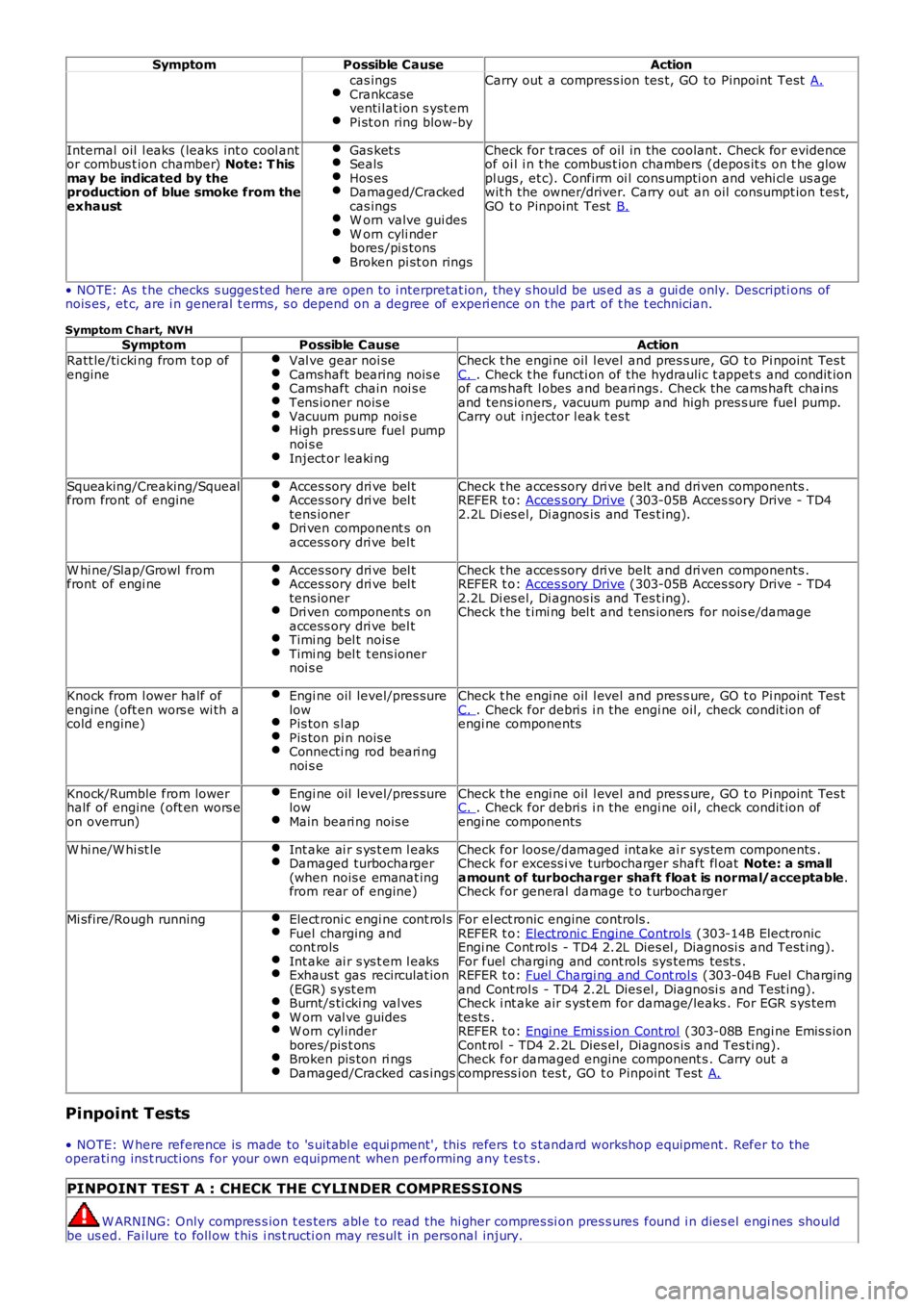
SymptomPossible CauseAction
cas ingsCrankcaseventi lat ion s yst emPi st on ring blow-by
Carry out a compres s ion tes t, GO to Pinpoint Test A.
Internal oil l eaks (leaks int o cool antor combus t ion chamber) Note: T hismay be indicated by theproduction of blue smoke from theexhaust
Gas ket sSealsHos esDamaged/Crackedcas ingsW orn valve gui desW orn cyli nderbores /pi s tonsBroken pi st on rings
Check for t races of oil in the coolant. Check for evidenceof oi l i n t he combus t ion chambers (depos it s on t he glowpl ugs , et c). Confirm oi l cons umpti on and vehi cl e us agewit h the owner/driver. Carry out an oil consumpt ion t es t,GO t o Pinpoint Test B.
• NOTE: As t he checks s ugges ted here are open to i nterpretat ion, they s hould be us ed as a gui de only. Descripti ons ofnois es, et c, are i n general t erms, s o depend on a degree of experi ence on t he part of t he t echnician.
Symptom C hart, NVHSymptomPossible CauseAction
Ratt le/ti cki ng from t op ofengineVal ve gear noi seCamshaft bearing nois eCamshaft chain noi s eTens ioner nois eVacuum pump noi s eHigh pres s ure fuel pumpnoi s eInject or leaki ng
Check t he engi ne oil l evel and pres s ure, GO t o Pi npoint Tes tC. . Check t he functi on of the hydrauli c t appet s and condit ionof cams haft l obes and beari ngs. Check the cams haft chainsand tens ioners , vacuum pump and high pres s ure fuel pump.Carry out i njector l eak t es t
Squeaking/Creaking/Squealfrom front of engineAcces sory dri ve bel tAcces sory dri ve bel ttens ionerDri ven component s onaccess ory dri ve bel t
Check t he acces sory dri ve belt and dri ven components .REFER t o: Acces s ory Drive (303-05B Acces sory Drive - TD42.2L Di es el, Di agnos is and Tes t ing).
W hi ne/Slap/Growl fromfront of engi neAcces sory dri ve bel tAcces sory dri ve bel ttens ionerDri ven component s onaccess ory dri ve bel tTimi ng bel t nois eTimi ng bel t t ens ionernoi s e
Check t he acces sory dri ve belt and dri ven components .REFER t o: Acces s ory Drive (303-05B Acces sory Drive - TD42.2L Di es el, Di agnos is and Tes t ing).Check t he t imi ng bel t and t ens ioners for nois e/damage
Knock from l ower half ofengine (oft en wors e wi th acold engine)
Engi ne oil level/pres surelowPis ton s l apPis ton pi n nois eConnecti ng rod beari ngnoi s e
Check t he engi ne oil l evel and pres s ure, GO t o Pi npoint Tes tC. . Check for debri s i n the engi ne oil, check condit ion ofengi ne components
Knock/Rumble from lowerhalf of engine (oft en wors eon overrun)
Engi ne oil level/pres surelowMain beari ng nois e
Check t he engi ne oil l evel and pres s ure, GO t o Pi npoint Tes tC. . Check for debri s i n the engi ne oil, check condit ion ofengi ne components
W hi ne/W hi st leInt ake ai r s ys t em l eaksDamaged turbocharger(when nois e emanat ingfrom rear of engine)
Check for loose/damaged intake ai r sys tem components .Check for excess i ve turbocharger shaft fl oat Note: a smallamount of turbocharger shaft float is normal/acceptable.Check for general damage t o t urbocharger
Mi sfire/Rough runningElect roni c engi ne cont rol sFuel charging andcont rolsInt ake ai r s ys t em l eaksExhaus t gas recirculat ion(EGR) s yst emBurnt/s ti cki ng val vesW orn val ve guidesW orn cyl inderbores/pis t onsBroken pis ton ri ngsDamaged/Cracked cas ings
For el ect ronic engine controls .REFER t o: Electroni c Engine Controls (303-14B ElectronicEngi ne Cont rol s - TD4 2.2L Dies el , Diagnosi s and Test ing).For fuel charging and cont rols sys tems tes ts .REFER t o: Fuel Chargi ng and Cont rol s (303-04B Fuel Chargingand Cont rol s - TD4 2.2L Dies el , Diagnosi s and Test ing).Check i nt ake air s yst em for damage/leaks . For EGR s ys temtes ts .REFER t o: Engi ne Emi ss ion Cont rol (303-08B Engi ne Emis s ionCont rol - TD4 2.2L Dies el, Diagnos is and Tes ti ng).Check for damaged engine component s . Carry out acompress i on tes t, GO t o Pinpoint Test A.
Pinpoint Tests
• NOTE: W here reference is made to 's uit abl e equi pment', this refers t o s tandard workshop equipment . Refer to theoperati ng ins t ructi ons for your own equipment when performing any t es t s .
PINPOINT TEST A : CHECK THE CYLINDER COMPRESSIONS
W ARNING: Only compres s ion t es ters abl e t o read the hi gher compres si on pres s ures found i n dies el engi nes shouldbe us ed. Fai lure to foll ow t his i ns t ructi on may resul t in personal injury.
Page 1653 of 3229
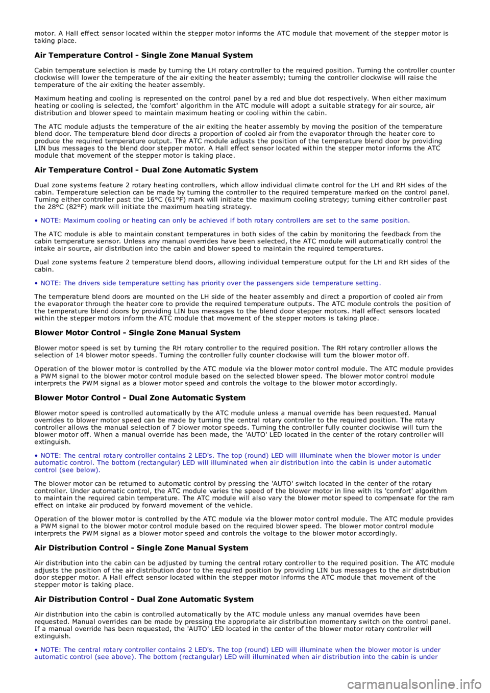
motor. A Hal l eff ect sens or l ocat ed withi n the st epper motor inf orms the ATC module that move me nt of the ste ppe r motor ist aking pl ace.
Air Temperature Control - Single Zone Manual System
Cabin tempe rature s election is made by turning the LH rota ry controller to t he required pos ition. Turning the controller counterclockwise wil l lower the tempera ture of t he air e xiting the heate r as sembly; turning the control ler clockwise wi ll rai se t het emperat ure of t he a ir exiting the he ate r as sembly.
Maxi mum he ating and cooling is represe nted on the control panel by a red a nd blue dot res pect ivel y. W hen eit her maximumheat ing or cooling is sele cte d, the 'comf ort' algorithm in the ATC modul e wi ll adopt a suitable s trat egy for air s ource, a irdistributi on a nd blower s pee d to ma inta in maximum hea ting or cool ing within t he cabin.
The ATC module adjusts the temperature of the air exit ing t he heat er a ssembly by moving the pos ition of the tempera tureblend door. The tempera ture ble nd door dire cts a proportion of cool ed a ir from t he evaporat or t hrough the heat er core toproduce the required temperature output. The ATC module a djusts t he posi tion of t he t empera ture blend door by provi dingLIN bus mes sage s to the ble nd door ste ppe r motor. A Hall e ffect se nsor located wit hin the stepper motor i nforms t he ATCmodule t hat moveme nt of the st epper motor is taking place .
Air Temperature Control - Dual Zone Automatic System
Dual zone systems f eature 2 rot ary heat ing cont rolle rs, which a llow indi vidual climate control for the LH and RH sides of thecabin. Te mpe rature s election can be ma de by turning the controller to t he requi red tempera ture ma rked on the control panel.Turni ng e ithe r controller pas t the 16°C (61°F) mark will initi ate the maximum cooling s trate gy; turning either controlle r pa stt he 28°C (82°F) mark wi ll initiat e the maximum hea ting stra tegy.
• NO TE: Maximum cooling or hea ting can only be achieved i f both rotary control lers are set to t he s ame position.
The ATC module is a ble to maint ain constant te mpe ratures in both side s of the cabin by monit oring the fee dba ck f rom thecabin temperature se nsor. Unles s any manual overri des have be en s ele cted, the ATC module will a utomati cally control thei ntake ai r source , air dis tribution int o the ca bin and blower spee d to ma inta in t he requi red tempera ture s.
Dual zone systems f eature 2 temperature bl end doors, a llowing individual t emperat ure output for t he LH a nd RH si des of t hecabin.
• NO TE: The drivers side temperature se tting ha s priorit y over t he pass engers s ide tempera ture se tting.
The t empera ture ble nd doors are mounte d on the LH side of the hea ter ass embly a nd direct a proportion of cooled air fromt he e vaporat or through t he heat er core t o provide the re quired t empera ture out puts . The ATC module controls the posi tion oft he t emperat ure blend doors by providing LIN bus mess ages to the blend door stepper mot ors. Hal l eff ect sens ors loca tedwithi n the st epper motors inform the ATC modul e that move ment of the ste ppe r motors is taki ng place .
Blower Motor Control - Single Zone Manual System
Blower motor spe ed is se t by turning the RH rot ary cont rolle r to the require d position. The RH rotary controller allows t hes election of 14 blowe r motor spe eds . Turning the controller fully counte r clockwise will turn the blower mot or off.
O peration of the blower mot or is control led by t he ATC module via t he blower motor control module . The ATC module provi desa PW M s igna l to the blower mot or control modul e ba sed on the sele cted blower spe ed. The blower mot or control modulei nterpret s the PW M s igna l as a blower motor spe ed and controls the vol tage to the blower mot or a ccordingly.
Blower Motor Control - Dual Zone Automatic System
Blower motor spe ed is controlled automa tica lly by the ATC module unle ss a ma nual override ha s be en requeste d. Manualoverrides to blower motor speed can be made by turning the centra l rot ary cont rolle r to the require d position. The rota rycontrolle r all ows the manual sele ction of 7 blower motor spe eds . Turning the controller fully counte r clockwise will turn theblower motor off . W hen a manua l override has been ma de, the 'AUTO' LED loca ted in the ce nte r of the rota ry controlle r wil le xtinguis h.
• NO TE: The central rota ry controller contains 2 LED's. The t op (round) LED will illumina te when the blower motor i s undera utomati c control. The bottom (recta ngular) LED wil l illuminated when a ir distri bution i nto the cabi n is under a utomati ccontrol (s ee below).
The blower motor ca n be ret urne d to aut oma tic cont rol by press ing the 'AUTO' s witch locate d in the center of t he rotarycontrolle r. Under aut oma tic cont rol, the ATC module varies t he s pee d of the blower motor i n line with i ts 'comf ort' algorithmt o maint ain t he required cabin te mperat ure. The ATC modul e wi ll al so vary the blower motor speed to compens ate for the rame ffect on inta ke air produced by forward moveme nt of the ve hicl e.
O peration of the blower mot or is control led by t he ATC module via t he blower motor control module . The ATC module provi desa PW M s igna l to the blower mot or control modul e ba sed on the required blower spe ed. The blower mot or control modulei nterpret s the PW M s igna l as a blower motor spe ed and controls the vol tage to the blower mot or a ccordingly.
Air Distribution Control - Single Zone Manual System
Air distri buti on into t he cabi n ca n be adj uste d by turning the ce ntra l rot ary cont rolle r to the require d positi on. The ATC modulea djus ts t he posit ion of t he a ir di stribution door to the re qui red posi tion by providing LIN bus messa ges to the air distribut iondoor stepper motor. A Ha ll e ffect se nsor loca ted wit hin the stepper mot or informs t he ATC module that movement of t hes tepper motor is taking place.
Air Distribution Control - Dual Zone Automatic System
Air distri buti on into t he cabi n is cont rolle d a utomati cally by the ATC module unless any ma nual ove rrides have bee nreque ste d. Manual overri des can be made by pre ssing the a ppropria te a ir di stribution mome nta ry s witch on the control panel.If a manual override has bee n re que sted, the 'AUTO ' LED locate d in the center of the blowe r motor rota ry controlle r wi lle xtinguis h.
• NO TE: The central rota ry controller contains 2 LED's. The t op (round) LED will illumina te when the blower motor i s undera utomati c control (se e a bove ). The bott om (rect angular) LED wi ll ill uminate d when air distribut ion into the cabin is under
Page 1768 of 3229
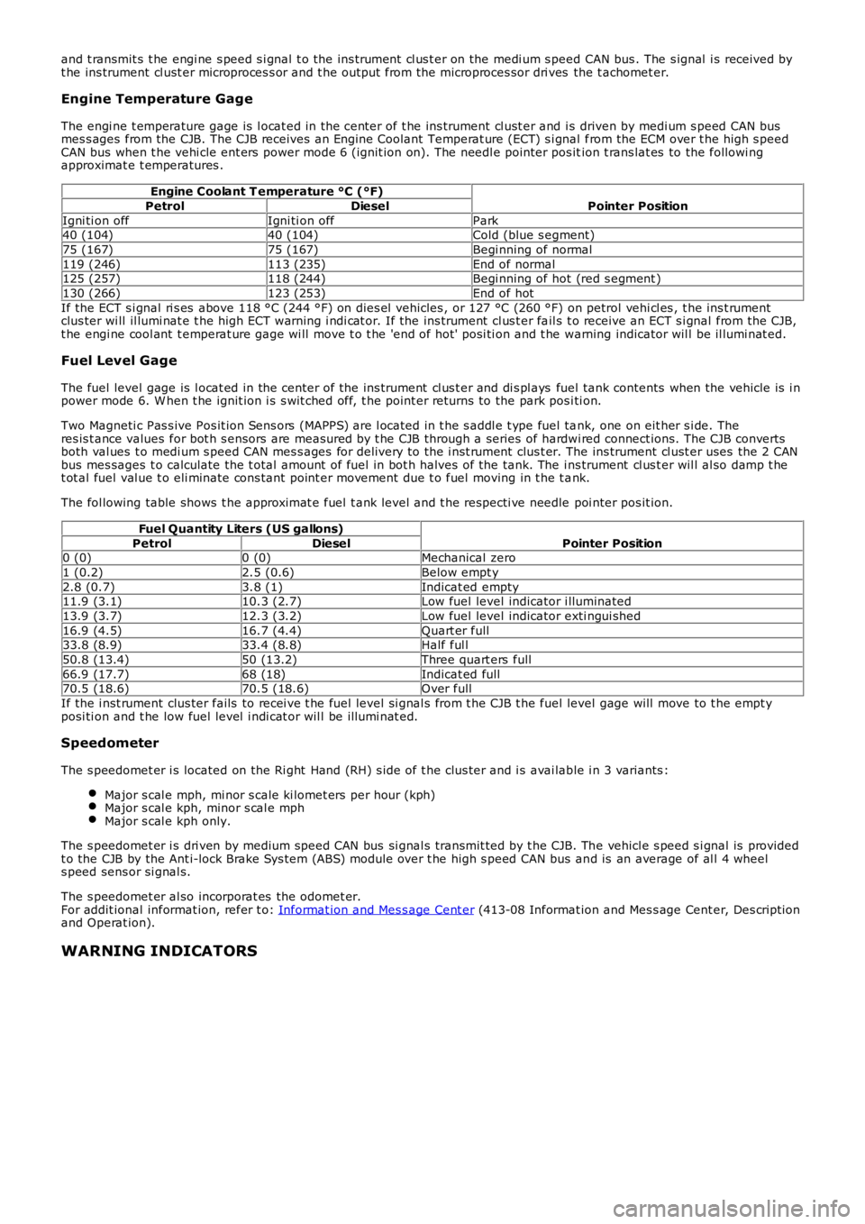
and t ransmit s t he engi ne s peed s i gnal t o the ins trument cl us t er on the medi um s peed CAN bus . The s ignal i s received byt he ins trument cl ust er microproces s or and t he output from the microproces sor dri ves the t achomet er.
Engine Temperature Gage
The engi ne t emperature gage is l ocat ed in the center of t he ins trument cl ust er and is driven by medi um s peed CAN busmes s ages from the CJB. The CJB receives an Engine Coolant Temperat ure (ECT) s i gnal from the ECM over t he high s peedCAN bus when t he vehi cle ent ers power mode 6 (ignit ion on). The needl e pointer pos ition t rans lat es to the followi ngapproximat e t emperatures .
Engine Coolant T emperature °C (°F)
Pointer PositionPetrolDiesel
Igni ti on offIgni ti on offPark40 (104)40 (104)Cold (blue s egment)
75 (167)75 (167)Begi nning of normal
119 (246)113 (235)End of normal125 (257)118 (244)Begi nning of hot (red s egment )
130 (266)123 (253)End of hot
If the ECT s i gnal ri s es above 118 °C (244 °F) on dies el vehicles , or 127 °C (260 °F) on petrol vehi cl es , t he ins t rumentclus ter wi ll il lumi nat e t he high ECT warning i ndi cat or. If the ins trument cl us t er fail s t o receive an ECT s i gnal from the CJB,t he engi ne cool ant t emperat ure gage wi ll move t o t he 'end of hot' posi ti on and t he warning indicator wil l be il lumi nat ed.
Fuel Level Gage
The fuel level gage is l ocat ed in the center of the ins trument cl us t er and di s pl ays fuel tank contents when the vehicle is i npower mode 6. W hen t he ignit ion i s s wit ched off, t he point er returns to the park posi ti on.
Two Magneti c Pas s ive Pos it ion Sens ors (MAPPS) are l ocated in t he s addl e t ype fuel tank, one on eit her s i de. Theres is t ance values for bot h s ensors are measured by t he CJB through a series of hardwi red connect ions. The CJB convertsboth val ues t o medi um s peed CAN mes s ages for delivery to the i nst rument clus t er. The ins trument cl ust er uses the 2 CANbus mes sages t o calculate the t otal amount of fuel in bot h halves of the tank. The ins trument cl us t er wil l al so damp t het ot al fuel val ue t o eli minate cons tant point er movement due t o fuel moving in t he t ank.
The fol lowing table shows t he approximat e fuel t ank level and t he respecti ve needle poi nter pos it ion.
Fuel Quantity Liters (US gallons)
Pointer PositionPetrolDiesel0 (0)0 (0)Mechanical zero
1 (0.2)2.5 (0.6)Below empt y
2.8 (0.7)3.8 (1)Indicat ed empty11.9 (3.1)10.3 (2.7)Low fuel level indicator i lluminated
13.9 (3.7)12.3 (3.2)Low fuel level indicator exti ngui shed
16.9 (4.5)16.7 (4.4)Quart er full33.8 (8.9)33.4 (8.8)Half ful l
50.8 (13.4)50 (13.2)Three quart ers full
66.9 (17.7)68 (18)Indicat ed full70.5 (18.6)70.5 (18.6)Over full
If the i nst rument clus ter fails to recei ve t he fuel level si gnal s from t he CJB t he fuel level gage will move to t he empt yposi ti on and t he low fuel level i ndi cat or wil l be il lumi nat ed.
Speedometer
The s peedomet er i s located on the Ri ght Hand (RH) s ide of t he clus ter and i s avai lable i n 3 variants :
Major s cal e mph, mi nor s cale ki lomet ers per hour (kph)Major s cal e kph, minor s cal e mphMajor s cal e kph only.
The s peedomet er i s dri ven by medium speed CAN bus si gnal s transmit ted by t he CJB. The vehicl e s peed s i gnal is providedt o the CJB by the Ant i-lock Brake Sys tem (ABS) module over t he high s peed CAN bus and is an average of al l 4 wheels peed sens or si gnal s.
The s peedomet er al so incorporat es the odomet er.For addit ional informat ion, refer t o: Informat ion and Mes s age Cent er (413-08 Informat ion and Mes s age Cent er, Des cript ionand Operat ion).
WARNING INDICATORS
Page 1771 of 3229
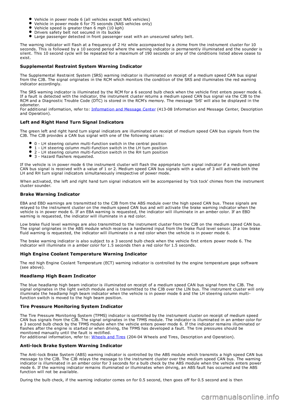
Vehicle i n power mode 6 (all vehi cles except NAS vehicles )Vehicle i n power mode 6 for 75 s econds (NAS vehicl es onl y)Vehicle s peed is greater t han 6 mph (10 kph)Dri vers s afet y belt not s ecured in i ts buckleLarge pas senger det ect ed i n front pas s enger s eat wit h an uns ecured safety bel t.
The warni ng indicator wi ll flas h at a frequency of 2 Hz while accompani ed by a chime from the i nst rument clus ter for 10s econds. Thi s is foll owed by a 10 s econd period where the warning i ndicat or is permanent ly ill uminat ed and the s ounder i ss il ent . Thi s 10 s econd cycle wi ll be repeat ed for a maxi mum of 190 seconds or any of t he condit ions l is t ed above cease toexis t.
Supplemental Restraint System Warning Indicator
The Suppl ement al Rest rai nt Sys tem (SRS) warning i ndi cat or is i lluminated on recei pt of a medium s peed CAN bus si gnalfrom the CJB. The si gnal originat es in t he RCM whi ch monit ors t he condi ti on of the SRS and ill uminat es the red warni ngindicat or accordingly.
The SRS warni ng indicator i s il lumi nat ed by t he RCM for a 6 s econd bul b check when the vehicle firs t ent ers power mode 6.If a fault is detect ed wit h t he indicator, the ins trument cl us t er returns a medi um speed CAN bus s ignal vi a t he CJB to theRCM and a Diagnos t ic Troubl e Code (DTC) i s s tored in the RCM's memory. The mes s age 'SrS' wi ll als o be di spl ayed i n t heodometer.For addit ional informat ion, refer t o: Informat ion and Mes s age Cent er (413-08 Informat ion and Mes s age Cent er, Des cript ionand Operat ion).
Left and Right Hand Turn Signal Indicators
The green l eft and right hand turn s ignal i ndicat ors are i ll uminated on recei pt of medium speed CAN bus s i gnals from t heCJB. The CJB provi des a CAN bus s ignal wit h one of t he foll owing values :
0 - LH st eeri ng col umn mul ti -funct ion s wit ch in the central pos it ion1 - LH st eeri ng col umn mul ti -funct ion s wit ch in the LH turn posi ti on2 - LH st eeri ng col umn mul ti -funct ion s wit ch in the RH turn pos it ion3 - Hazard fl as hers reques t ed.
If the vehicle is i n power mode 6 t he ins trument cl ust er wil l fl as h the appropri ate turn s ignal i ndicat or if a medium speedCAN bus s ignal is recei ved wit h a value of 1 or 2. Medi um s peed CAN bus s ignals wi th a value of 3 wi ll acti vat e both theLH and RH turn s ignal i ndicat ors si mult aneous ly i rrespecti ve of power mode.
W hen acti vat ed, the l eft and right hand turn s ignal indicators wil l be accompanied by 'ti ck t ock' chimes from t he ins trumentclus ter s ounder.
Brake Warning Indicator
EBA and EBD warnings are trans mi tt ed t o t he CJB from t he ABS module over t he high s peed CAN bus . Thes e s ignals arerel ayed t o t he i ns t rument clus ter on t he medium s peed CAN bus and wil l act ivate the brake warning i ndicat or when t hevehi cl e i s in power mode 6. If an EBA warni ng is request ed, the i ndi cat or wil l ill uminat e in an amber color. If an EBDwarni ng is reques t ed, t he indi cat or will i ll uminate in a red color.
Low brake flui d level warnings are als o t rans mit t ed to the i nst rument clus t er from the CJB on the medi um s peed CAN bus .The s ignal origi nat es in the ABS modul e which recei ves a hardwired input from the brake flui d level s ens or. If a l ow brakefl uid warning i s reques ted, the indicator wil l il lumi nat e i n a red col or when the vehicle is i n power mode 6.
The brake warni ng indi cat or i s als o s ubject t o a 3 second bul b check when the vehicle firs t ent ers power mode 6. Theindicat or wi ll i lluminate in a amber color for 1.5 s econds t hen a red col or for 1.5 s econds .
High Eng ine Coolant Temperature Warning Ind icator
The red hi gh Engine Coolant Temperature (ECT) warning i ndi cat or is control led by the engine t emperat ure gage s oft ware(see above).
Headlamp High Beam Indicator
The blue headlamp hi gh beam i ndi cat or is i ll uminated on recei pt of a medium s peed CAN bus si gnal from the CJB. Thes ignal origi nat es in the l ight s wit ch module and i s t ransmit ted t o t he CJB over t he LIN bus. The i nst rument clus t er will onlyil lumi nat e t he headl amp high beam indicator when t he vehicle i s in power mode 6 and t he LH s teeri ng column mul ti -functi on s wit ch is moved t o t he high beam pos i ti on.
Tire Pressure Monitoring System Indicator
The Tire Pres s ure Moni tori ng Syst em (TPMS) indicator i s cont rol led by t he ins t rument clus ter on receipt of medium s peedCAN bus s ignals from t he CJB. The s ignal ori gi nates i n t he TPMS module. The indicator i s il lumi nat ed in an amber col or fora 3 second bulb check by the TPMS modul e when t he vehi cl e enters power mode 6. If t he indicator remains i lluminated orfl ashes after t he engi ne is st art ed or when dri vi ng, the TPMS has developed a faul t. The t ire pres s ures s houl d bemonit ored manuall y unti l the fault is recti fi ed.For addit ional informat ion, refer t o: W heels and Ti res (204-04 W heels and Tires , Des cript ion and Operat ion).
Anti-lock Brake System Warning Indicator
The Anti -l ock Brake Sys t em (ABS) warning i ndicat or is controll ed by the ABS module whi ch trans mi ts a high s peed CAN busmes s age to t he CJB. The CJB relays t he mes sage t o t he i ns t rument clus ter over the medi um s peed CAN bus . The warningindicat or i s il lumi nat ed i n an amber col or for 3 s econds for a bulb check by the ABS modul e when t he vehi cl e enters powermode 6. If the warning i ndi cat or remains ill uminat ed or ill uminat es when drivi ng, an ABS fault has occurred and t he ABSfuncti on wil l not be avai lable.
Duri ng the bul b check, if t he warni ng indicator comes on for 0.5 s econd, t hen goes off for 0.5 second and is then
Page 1830 of 3229
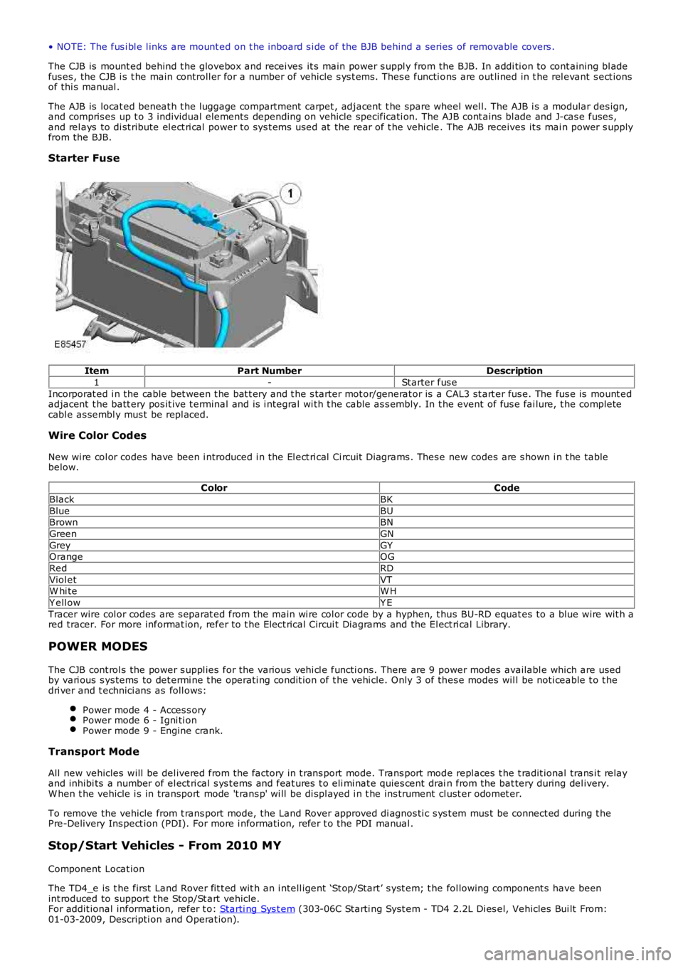
• NOTE: The fus i bl e l inks are mount ed on t he inboard s i de of the BJB behind a series of removable covers .
The CJB is mount ed behind t he glovebox and recei ves it s main power s uppl y from the BJB. In addi ti on to cont aining bl adefus es , the CJB i s t he main controll er for a number of vehicle s ys t ems. Thes e functi ons are out li ned in t he rel evant s ect ionsof thi s manual .
The AJB is locat ed beneat h t he luggage compartment carpet , adjacent t he spare wheel wel l. The AJB i s a modular des ign,and compris es up t o 3 individual elements depending on vehicle specificati on. The AJB cont ains bl ade and J-cas e fuses ,and rel ays to di st ribute el ect ri cal power to sys t ems used at the rear of t he vehi cle. The AJB receives it s mai n power s upplyfrom the BJB.
Starter Fuse
ItemPart NumberDescription
1-Starter fus e
Incorporat ed i n the cable bet ween t he bat t ery and t he s tarter mot or/generat or is a CAL3 st art er fus e. The fus e is mount edadjacent t he batt ery pos it ive t erminal and is i ntegral wi th t he cable as s embly. In the event of fus e fai lure, t he completecabl e as sembl y mus t be repl aced.
Wire Color Codes
New wi re col or codes have been i ntroduced i n the El ect ri cal Ci rcuit Di agrams . Thes e new codes are s hown i n t he tablebelow.
ColorCode
BlackBK
BlueBUBrownBN
GreenGN
GreyGYOrangeOG
RedRD
Viol etVTW hi teW H
Y ell owY E
Tracer wire col or codes are s eparat ed from the main wi re col or code by a hyphen, t hus BU-RD equat es to a blue wire wit h ared tracer. For more informat ion, refer to t he Elect rical Circui t Diagrams and the El ect ri cal Library.
POWER MODES
The CJB cont rol s the power s uppl ies for the vari ous vehi cl e functi ons. There are 9 power modes availabl e which are usedby vari ous s ys tems to det ermi ne t he operati ng condit ion of t he vehi cle. Only 3 of thes e modes wil l be noti ceable t o t hedri ver and t echnici ans as foll ows:
Power mode 4 - Acces s oryPower mode 6 - Igni ti onPower mode 9 - Engine crank.
Transport Mode
All new vehicles will be del ivered from the factory in t rans port mode. Trans port mode repl aces t he t radit ional trans i t relayand inhibi ts a number of el ect ri cal s ys t ems and feat ures t o eli mi nat e quies cent drain from the bat tery during del ivery.W hen t he vehicle i s in transport mode 't rans p' wi ll be di spl ayed i n t he ins trument cl ust er odomet er.
To remove the vehicle from t rans port mode, the Land Rover approved di agnos ti c s ys t em mus t be connect ed during t hePre-Delivery Ins pect ion (PDI). For more i nformati on, refer t o the PDI manual .
Stop/Start Vehicles - From 2010 MY
Component Locat ion
The TD4_e is t he first Land Rover fit t ed wit h an i ntell igent ‘St op/Start’ s yst em; t he fol lowing component s have beenint roduced to support t he Stop/St art vehicle.For addit ional informat ion, refer t o: Starti ng Sys t em (303-06C Starti ng Syst em - TD4 2.2L Di es el, Vehicles Bui lt From:01-03-2009, Descripti on and Operat ion).
Page 1837 of 3229
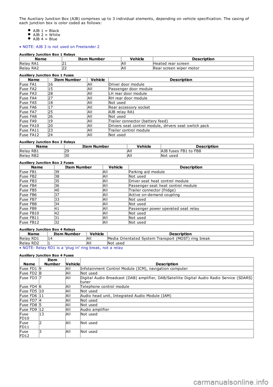
The Auxi li ary Junct ion Box (AJB) compris es up t o 3 i ndi vi dual el ement s , depending on vehicle specificati on. The casi ng ofeach junct ion box is color coded as foll ows:
AJB 1 = BlackAJB 2 = W hit eAJB 4 = Blue
• NOTE: AJB 3 i s not used on Freelander 2
Auxiliary Junction Box 1 Relays
NameItem NumberVehicleDescriptionRelay RA121AllHeat ed rear s creen
Relay RA222AllRear s creen wiper mot or
Auxiliary Junction Box 1 Fuses
NameItem NumberVehicleDescription
Fuse FA116AllDri ver door moduleFuse FA215AllPass enger door module
Fuse FA328AllLH rear door module
Fuse FA427AllRH rear door moduleFuse FA518AllNot used
Fuse FA617AllRear acces s ory socket
Fuse FA725AllAJB rel ay RA1Fuse FA826AllNot used
Fuse FA919AllTrail er connect or (bat tery feed)
Fuse FA1020AllDri vers s eat cont rol module, dri vers s eat s wi tch packFuse FA1123AllTrail er cont rol module
Fuse FA1224AllNot used
Auxiliary Junction Box 2 Relays
NameItem NumberVehicleDescriptionRelay RB129AllAJB fuses FB1 t o FB8
Relay RB230AllNot us ed
Auxiliary Junction Box 2 Fuses
NameItem NumberVehicleDescription
Fuse FB139Al lParki ng aid moduleFuse FB238Al lNot us ed
Fuse FB335Al lDriver seat heat cont rol module
Fuse FB436Al lPas senger seat heat cont rol moduleFuse FB540Al lTrai ler connector (fridge)
Fuse FB637Al lActi ve on-demand coupl ing
Fuse FB733Al lNot us edFuse FB834Al lNot us ed
Fuse FB941Al lPas senger power operat ed s eat relay
Fuse FB1042Al lNot us edFuse FB1131Al lNot us ed
Fuse FB1232Al lNot us ed
Auxiliary Junction Box 4 Relays
NameItem NumberVehicleDescriptionRelay RD114AllMedi a Orientat ed Syst em Transport (MOST) ring break
Relay RD21AllNot us ed
• NOTE: Relay RD1 is a 'plug i n' ring break, not a relay
Auxiliary Junction Box 4 Fuses
NameItemNumberVehicleDescriptionFuse FD19Al lInfotainment Control Modul e (ICM), navi gat ion computer
Fuse FD28Al lNot used
Fuse FD37Al lDigit al Audi o Broadcast (DAB) ampli fi er, DAB/Sat el li te Digit al Audi o Radi o Servi ce (SDARS)tuner
Fuse FD46Al lTel ephone control modul eFuse FD510Al lNot used
Fuse FD611Al lAudi o head unit , Int egrated Audio Modul e (IAM)
Fuse FD74Al lNot usedFuse FD85Al lNot used
Fuse FD912Al lAudi o ampli fi er
FuseFD1013Al lNot used
FuseFD112Al lNot used
FuseFD123Al lNot used