2006 LAND ROVER FRELANDER 2 alarm
[x] Cancel search: alarmPage 40 of 3229
s tored on open ground coul d eit her leak or have contami nati ng subs tances was hed off them that would cont aminate theland. Always s tore t hes e materi als i n s uit abl e s kips or s imi larly robus t cont ainers .
Legal compliance
Some s it es may have a di scharge cons ent for effl uent di scharge t o t he foul drai n for a car was h et c. It is ess enti al t o knowt he types of effluent which are al lowed t o be di scharged i nto t he drai n and t o check t he res ult s of any monit ori ng carri edout by the W ater Company.
W here paint s praying operat ions are carried out i t may be necess ary to apply to the Local Aut horit y for an ai r emis s ionsli cence t o operate the pl ant . If such a licence is necess ary, addit ional precaut ions wil l be neces s ary t o comply wi th therequirements and t he resul ts of any air quali ty moni toring mus t be checked regul arl y.
Checkli s t
Alw ays adhere to the following:
Know what legal cons ents and l icences apply t o t he operat ions.
Check t hat the emis s ions and dis charges compl y wit h l egal requi rements .
Waste Management
Pollut ion can be reduced by careful handli ng, s t orage and dis posal of all was te materials that occur on s it es. Legis lat ionmakes it i ll egal t o dis pose of was t e mat eri al s other t han to licens ed wast e carriers and dis pos al s it es.
This means t hat it i s neces sary t o not onl y know what the wast e mat eri al s are but als o to have the neces s arydocument at ion and licences .
Handl ing and s t orage of was te
Ensure t hat was t e mat erial s are not poured down the drai n or on t o s oil and are st ored in s uch a way t hat they do notes cape on t o l and or soi l.
All was te mus t be s egregat ed int o i ndi vi dual t ypes e.g. oils , met als , bat t eries , s crap component s etc. This wi ll prevent anyreacti on between di fferent materials and as s is t i n dis posal .
Dis pos al of was te
Dis pos e of wast e i n accordance wi th t he followi ng guidelines :
Fuel, hydraulic fluid, anti-freeze and oil: Keep s eparate and dis pos e of t o s peci alis t contract ors .
Refrigerant: Col lect in s peci ali st equipment and reus e.
Detergents: Safe to pour down t he foul drai n if di luted.
Paint, thinners: Keep separat e and dis pose of to speciali st contract or.
Components: Return t o s uppl ier for refurbi shment or dis as sembl e and reus e any s uit able part s . Dis pose ofremai nder i n ordi nary was te.
Small parts: Reuse any sui table parts , dis pos e of the remainder in ordinary was t e.
Metals: Can be s old i f separat e from general was t e.
T yres: Keep s eparate and di s pos e of t o s peci al is t cont ract or. DO NO T att empt to dis pos e of t yres by burni ng.
Components/materials containing asbestos: Keep separat e and dis pose of to speciali st contract or.
Oil and fuel wastes (e.g. rags, used spill kit material): Keep s eparate and dis pos e of t o s peci alis t contract ors .
Air filters: Keep s eparat e and dis pose of to s peciali st contract ors .
Rubber/plastics: Dis pos e of i n ordi nary was te.
Hoses: Di s pos e of i n ordinary was te.
Batteries: Keep separat e and dis pose of to speciali st contract ors .
Air bags - DANGER EXPLOSIVES: Keep s eparate and dis pos e of t o s peci alis t contract ors .
Electrical components: Return to suppli er for refurbis hment or dis ass emble and reus e any s uit abl e components .Dis pos e of remai nder in ordinary wast e.
Catalytic converters: May be s ol d i f kept s eparate from general wast e.
Packaging: Compact/recycl e as much as pos s ible and di s pos e of i n ordinary was te.
Office/paper waste: Recycl e paper and t oner and i nk cart ridges , dis pos e of remainder in ordinary was t e.
Noise
Car alarm t es t ing, panel beati ng, runni ng engi nes , us ing ai r tools et c. are operat ions which i nvariably produce a largeamount of noi se. The l ocati on of s uch act ivit ies and als o the t ime of day must be carefull y cons idered havi ng regard to theproximit y of hous es s chools et c.
Page 71 of 3229
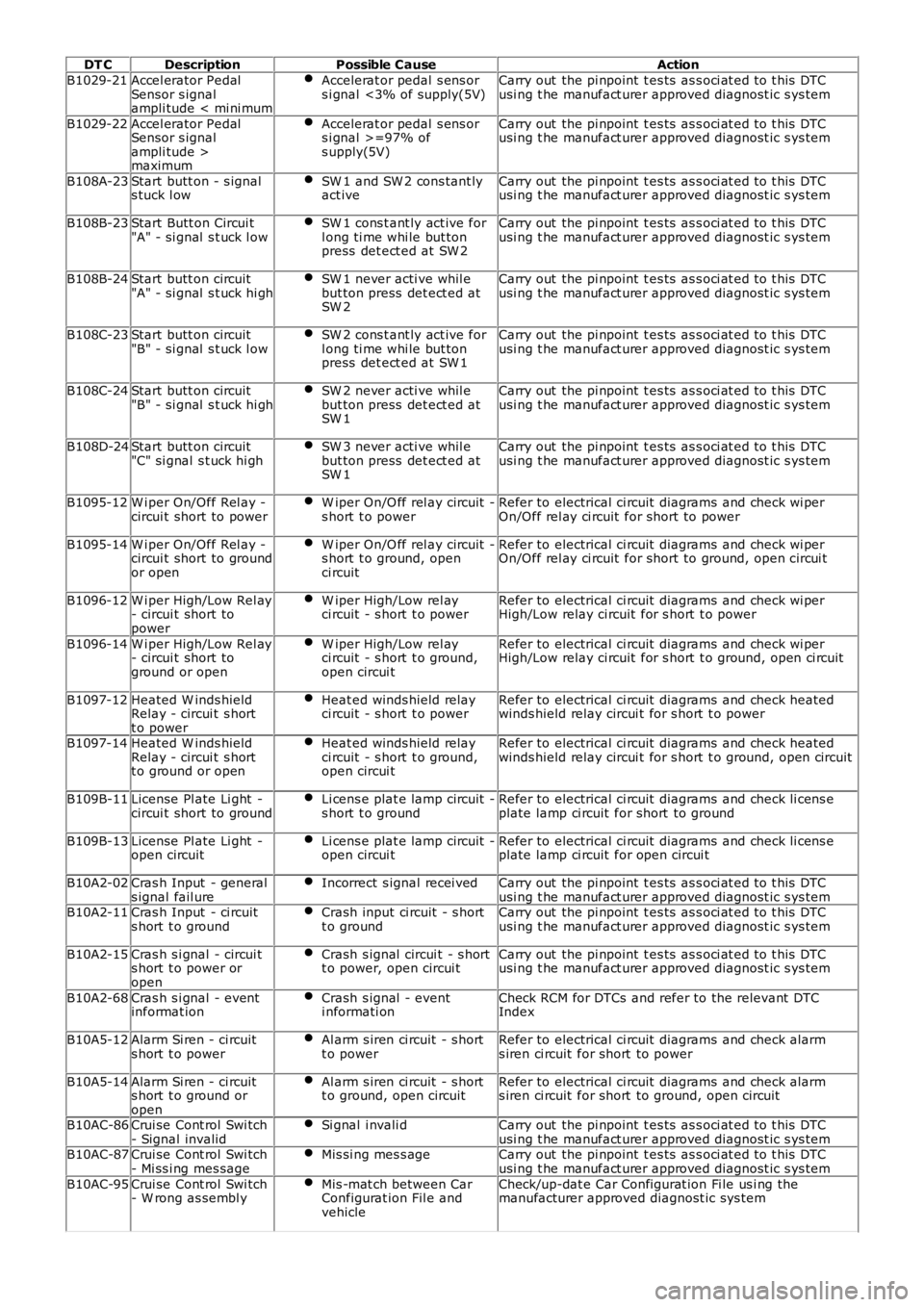
DT CDescriptionPossible CauseAction
B1029-21Accel erator PedalSensor s ignalampli tude < mi ni mum
Accelerat or pedal s ens ors i gnal <3% of supply(5V)Carry out the pi npoint t es ts as s oci at ed t o t his DTCusi ng t he manufact urer approved diagnost ic s ys tem
B1029-22Accel erator PedalSensor s ignalampli tude >maximum
Accelerat or pedal s ens ors i gnal >=97% ofs upply(5V)
Carry out the pi npoint t es ts as s oci at ed t o t his DTCusi ng t he manufact urer approved diagnost ic s ys tem
B108A-23Start butt on - s ignals tuck l owSW 1 and SW 2 cons tant lyact iveCarry out the pi npoint t es ts as s oci at ed t o t his DTCusi ng t he manufact urer approved diagnost ic s ys tem
B108B-23Start Butt on Circui t"A" - si gnal s t uck l owSW 1 cons t ant ly act ive forl ong ti me whi le but tonpress det ect ed at SW 2
Carry out the pi npoint t es ts as s oci at ed t o t his DTCusi ng t he manufact urer approved diagnost ic s ys tem
B108B-24Start butt on circuit"A" - si gnal s t uck hi ghSW 1 never acti ve whil ebut ton press det ect ed atSW 2
Carry out the pi npoint t es ts as s oci at ed t o t his DTCusi ng t he manufact urer approved diagnost ic s ys tem
B108C-23Start butt on circuit"B" - si gnal s t uck l owSW 2 cons t ant ly act ive forl ong ti me whi le but tonpress det ect ed at SW 1
Carry out the pi npoint t es ts as s oci at ed t o t his DTCusi ng t he manufact urer approved diagnost ic s ys tem
B108C-24Start butt on circuit"B" - si gnal s t uck hi ghSW 2 never acti ve whil ebut ton press det ect ed atSW 1
Carry out the pi npoint t es ts as s oci at ed t o t his DTCusi ng t he manufact urer approved diagnost ic s ys tem
B108D-24Start butt on circuit"C" si gnal s t uck hi ghSW 3 never acti ve whil ebut ton press det ect ed atSW 1
Carry out the pi npoint t es ts as s oci at ed t o t his DTCusi ng t he manufact urer approved diagnost ic s ys tem
B1095-12W i per On/Off Rel ay -circui t short to powerW iper On/O ff rel ay circuit -s hort t o powerRefer to electrical ci rcuit diagrams and check wi perOn/Off rel ay ci rcuit for short to power
B1095-14W i per On/Off Rel ay -circui t short to groundor open
W iper On/O ff rel ay circuit -s hort t o ground, openci rcuit
Refer to electrical ci rcuit diagrams and check wi perOn/Off rel ay ci rcuit for short to ground, open circui t
B1096-12W i per High/Low Rel ay- circui t short topower
W iper High/Low rel ayci rcuit - s hort t o powerRefer to electrical ci rcuit diagrams and check wi perHigh/Low relay ci rcuit for s hort t o power
B1096-14W i per High/Low Rel ay- circui t short toground or open
W iper High/Low rel ayci rcuit - s hort t o ground,open circui t
Refer to electrical ci rcuit diagrams and check wi perHigh/Low relay ci rcuit for s hort t o ground, open ci rcuit
B1097-12Heated W inds hieldRelay - circui t s hortt o power
Heat ed winds hield relayci rcuit - s hort t o powerRefer to electrical ci rcuit diagrams and check heatedwinds hield relay circui t for s hort t o power
B1097-14Heated W inds hieldRelay - circui t s hortt o ground or open
Heat ed winds hield relayci rcuit - s hort t o ground,open circui t
Refer to electrical ci rcuit diagrams and check heatedwinds hield relay circui t for s hort t o ground, open ci rcuit
B109B-11License Pl ate Li ght -circui t short to groundLi cens e plat e lamp circuit -s hort t o groundRefer to electrical ci rcuit diagrams and check li cens eplate lamp ci rcuit for short to ground
B109B-13License Pl ate Li ght -open circuitLi cens e plat e lamp circuit -open circui tRefer to electrical ci rcuit diagrams and check li cens eplate lamp ci rcuit for open circui t
B10A2-02Cras h Input - generals ignal fail ureIncorrect s ignal recei vedCarry out the pi npoint t es ts as s oci at ed t o t his DTCusi ng t he manufact urer approved diagnost ic s ys temB10A2-11Cras h Input - ci rcuits hort t o groundCrash input ci rcuit - s hortt o groundCarry out the pi npoint t es ts as s oci at ed t o t his DTCusi ng t he manufact urer approved diagnost ic s ys tem
B10A2-15Cras h s i gnal - circui ts hort t o power oropen
Crash s ignal circui t - s hortt o power, open circui tCarry out the pi npoint t es ts as s oci at ed t o t his DTCusi ng t he manufact urer approved diagnost ic s ys tem
B10A2-68Cras h s i gnal - eventinformat ionCrash s ignal - eventi nformati onCheck RCM for DTCs and refer to the relevant DTCIndex
B10A5-12Alarm Si ren - ci rcuits hort t o powerAl arm s iren ci rcuit - s hortt o powerRefer to electrical ci rcuit diagrams and check alarms iren ci rcuit for short to power
B10A5-14Alarm Si ren - ci rcuits hort t o ground oropen
Al arm s iren ci rcuit - s hortt o ground, open circuitRefer to electrical ci rcuit diagrams and check alarms iren ci rcuit for short to ground, open circuit
B10AC-86Crui se Cont rol Swi tch- Signal invalidSi gnal i nvali dCarry out the pi npoint t es ts as s oci at ed t o t his DTCusi ng t he manufact urer approved diagnost ic s ys temB10AC-87Crui se Cont rol Swi tch- Mi ss i ng mes sageMis si ng mes s ageCarry out the pi npoint t es ts as s oci at ed t o t his DTCusi ng t he manufact urer approved diagnost ic s ys tem
B10AC-95Crui se Cont rol Swi tch- W rong as sembl yMis -mat ch between CarConfigurat ion Fil e andvehicle
Check/up-dat e Car Configurat ion Fi le us i ng themanufacturer approved diagnost ic sys tem
Page 74 of 3229
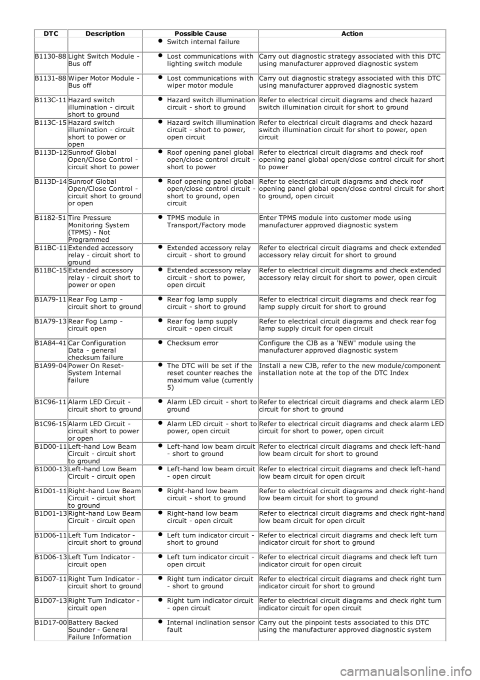
DT CDescriptionPossible CauseAction
Swi tch i nternal fai lure
B1130-88Light Swit ch Modul e -Bus offLos t communicat ions wi thl ight ing s wit ch moduleCarry out di agnos ti c s trategy as s ociat ed wi th t his DTCusi ng manufacturer approved diagnos ti c sys t em
B1131-88W i per Mot or Modul e -Bus offLos t communicat ions wi thwiper motor moduleCarry out di agnos ti c s trategy as s ociat ed wi th t his DTCusi ng manufacturer approved diagnos ti c sys t em
B113C-11Hazard s wi tchil lumi nat ion - ci rcuits hort t o ground
Hazard swit ch ill uminat ionci rcuit - s hort t o groundRefer to electrical ci rcuit diagrams and check hazards wit ch ill uminat ion circui t for s hort t o ground
B113C-15Hazard s wi tchil lumi nat ion - ci rcuits hort t o power oropen
Hazard swit ch ill uminat ionci rcuit - s hort t o power,open circui t
Refer to electrical ci rcuit diagrams and check hazards wit ch ill uminat ion circui t for s hort t o power, openci rcuit
B113D-12Sunroof GlobalOpen/Cl os e Cont rol -circui t short to power
Roof openi ng panel globalopen/clos e control ci rcuit -s hort t o power
Refer to electrical ci rcuit diagrams and check roofopeni ng panel global open/cl os e control ci rcuit for shortto power
B113D-14Sunroof GlobalOpen/Cl os e Cont rol -circui t short to groundor open
Roof openi ng panel globalopen/clos e control ci rcuit -s hort t o ground, openci rcuit
Refer to electrical ci rcuit diagrams and check roofopeni ng panel global open/cl os e control ci rcuit for shortto ground, open circui t
B1182-51Tire Pres s ureMonit ori ng Sys t em(TPMS) - NotProgrammed
TPMS modul e inTrans port /Factory modeEnt er TPMS module i nto cus tomer mode us i ngmanufacturer approved diagnost ic sys tem
B11BC-11Extended acces soryrel ay - circuit short toground
Ext ended acces s ory relayci rcuit - s hort t o groundRefer to electrical ci rcuit diagrams and check extendedacces sory rel ay ci rcuit for short to ground
B11BC-15Extended acces soryrel ay - circuit short topower or open
Ext ended acces s ory relayci rcuit - s hort t o power,open circui t
Refer to electrical ci rcuit diagrams and check extendedacces sory rel ay ci rcuit for short to power, open ci rcuit
B1A79-11Rear Fog Lamp -circui t short to groundRear fog lamp supplyci rcuit - s hort t o groundRefer to electrical ci rcuit diagrams and check rear foglamp supply ci rcuit for s hort t o ground
B1A79-13Rear Fog Lamp -circui t openRear fog lamp supplyci rcuit - open circuitRefer to electrical ci rcuit diagrams and check rear foglamp supply ci rcuit for open circui t
B1A84-41Car Configurat ionData - generalchecks um fai lure
Checks um errorConfigure the CJB as a 'NEW ' module usi ng t hemanufacturer approved diagnost ic sys tem
B1A99-04Power On Res et -Syst em Int ernalfai lure
The DTC wil l be set i f theres et counter reaches themaxi mum val ue (current ly5)
Ins t al l a new CJB, refer t o t he new module/componentins tal lati on note at the t op of the DTC Index
B1C96-11Alarm LED Ci rcuit -circui t short to groundAl arm LED circuit - short togroundRefer to electrical ci rcuit diagrams and check alarm LEDci rcuit for short to ground
B1C96-15Alarm LED Ci rcuit -circui t short to poweror open
Al arm LED circuit - short topower, open circui tRefer to electrical ci rcuit diagrams and check alarm LEDci rcuit for short to power, open ci rcuit
B1D00-11Left -hand Low BeamCircui t - circuit shortt o ground
Left-hand low beam ci rcuit- short to groundRefer to electrical ci rcuit diagrams and check left-handlow beam circuit for s hort to ground
B1D00-13Left -hand Low BeamCircui t - circuit openLeft-hand low beam ci rcuit- open circui tRefer to electrical ci rcuit diagrams and check left-handlow beam circuit for open ci rcuit
B1D01-11Right -hand Low BeamCircui t - circuit shortt o ground
Ri ght -hand l ow beamci rcuit - s hort t o groundRefer to electrical ci rcuit diagrams and check right-handlow beam circuit for s hort to ground
B1D01-13Right -hand Low BeamCircui t - circuit openRi ght -hand l ow beamci rcuit - open circuitRefer to electrical ci rcuit diagrams and check right-handlow beam circuit for open ci rcuit
B1D06-11Left Turn Indicator -circui t short to groundLeft turn indicator circui t -s hort t o groundRefer to electrical ci rcuit diagrams and check left turnindicator circui t for s hort t o ground
B1D06-13Left Turn Indicator -circui t openLeft turn indicator circui t -open circui tRefer to electrical ci rcuit diagrams and check left turnindicator circui t for open circuit
B1D07-11Right Turn Indicator -circui t short to groundRi ght turn indicator circui t- short to groundRefer to electrical ci rcuit diagrams and check right turnindicator circui t for s hort t o ground
B1D07-13Right Turn Indicator -circui t openRi ght turn indicator circui t- open circui tRefer to electrical ci rcuit diagrams and check right turnindicator circui t for open circuit
B1D17-00Batt ery BackedSounder - GeneralFailure Informat ion
Internal i ncl inati on s ens orfaultCarry out the pi npoint t es ts as s oci at ed t o t his DTCusi ng t he manufact urer approved diagnost ic s ys tem
Page 1683 of 3229
Publi s hed: 11-May-2011
Climate Control - EvaporatorLHD AWD
Removal and Inst all ati on
Removal
• NOTE: The removal of thi s component involves cut t ing an apert ure in t he evaporator hous i ng wall and cutt ing t hrought he high and l ow pres s ure A/C l ines. A s ervice repai r ki t is s uppli ed to cover thi s procedure.
Di sconnect t he bat t ery ground cable.
Refer t o: Specificati ons (414-00 Bat tery and Charging Sys tem -General Informat ion, Specificati ons).
1.
Recover t he A/C refrigerant .
Refer t o: Air Condi ti oning (A/C) Sys tem Recovery, Evacuati on andCharging (412-00 Cl imat e Control Sys t em - General Informat ion,General Procedures).
2.
Remove t he plenum chamber panel.
Refer t o: Plenum Chamber (412-01 Cl imat e Control, Removal andInst all at ion).
3.
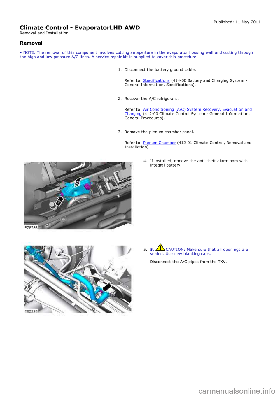
If ins tal led, remove t he anti -t heft alarm horn wit hi nt egral batt ery.4.
5. CAUTION: Make s ure that all openi ngs ares ealed. Use new blanking caps.
Di sconnect t he A/C pipes from t he TXV.
5.
Page 1690 of 3229
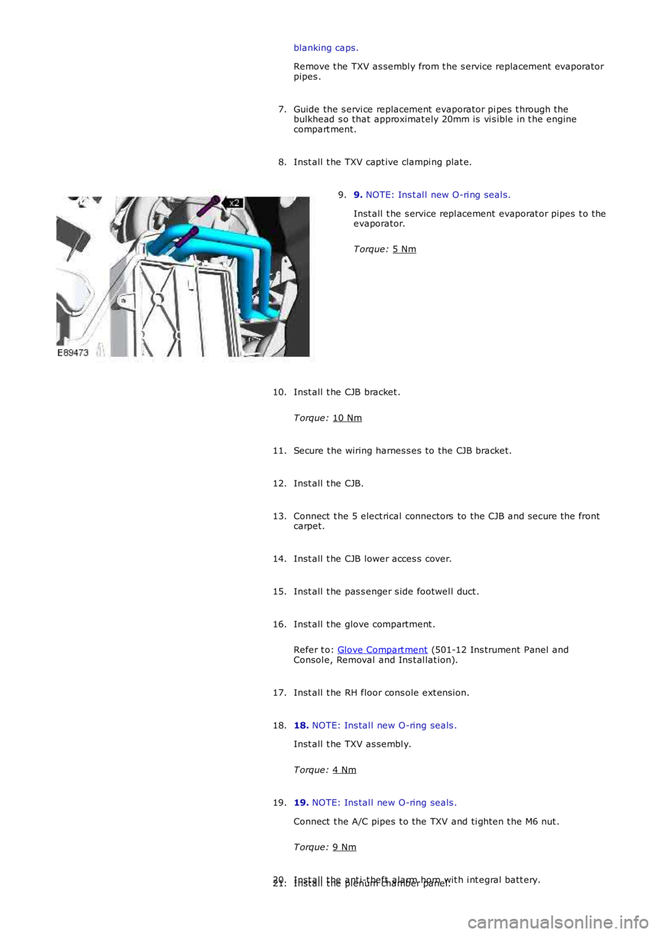
blanking caps.
Remove t he TXV as sembl y from t he s ervice replacement evaporator
pipes .
Guide the s ervi ce replacement evaporator pi pes t hrough t he
bulkhead s o that approximat ely 20mm is vi s ible in t he engine
compart ment.
7.
Inst all t he TXV capt ive clampi ng plat e.
8. 9.
NOTE: Ins t al l new O-ri ng seal s.
Inst all t he s ervice repl acement evaporat or pipes t o the
evaporator.
T orque: 5 Nm 9.
Inst all t he CJB bracket .
T orque: 10 Nm 10.
Secure t he wiring harnes s es to the CJB bracket.
11.
Inst all t he CJB.
12.
Connect t he 5 elect rical connectors to the CJB and s ecure t he front
carpet.
13.
Inst all t he CJB lower acces s cover.
14.
Inst all t he pas s enger s ide footwel l duct .
15.
Inst all t he glove compartment .
Refer t o: Glove Compart ment (501-12 Ins trument Panel and
Consol e, Removal and Ins t al lat ion).
16.
Inst all t he RH floor cons ole ext ens ion.
17.
18. NOTE: Ins tal l new O-ring seals .
Inst all t he TXV as sembl y.
T orque: 4 Nm 18.
19. NOTE: Ins tal l new O-ring seals .
Connect t he A/C pipes t o the TXV and ti ght en t he M6 nut .
T orque: 9 Nm 19.
Inst all t he ant i-t heft alarm horn wit h i nt egral batt ery.
20.
Inst all t he plenum chamber panel.
21.
Page 1770 of 3229
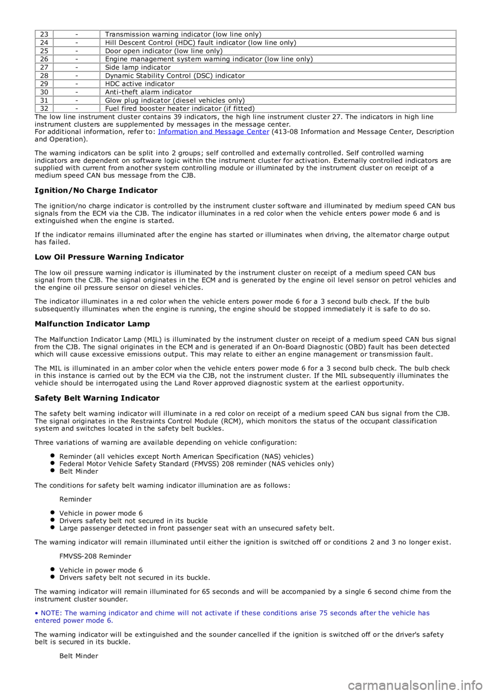
23-Transmis s ion warni ng indi cat or (low li ne only)
24-Hil l Des cent Cont rol (HDC) fault i ndi cat or (l ow li ne only)
25-Door open i ndi cat or (l ow li ne only)26-Engi ne management s yst em warning i ndicat or (l ow l ine only)
27-Side l amp indicat or
28-Dynami c Stabil it y Control (DSC) indicat or29-HDC acti ve indicator
30-Ant i-t heft alarm i ndi cat or
31-Glow pl ug indicat or (dies el vehicles onl y)32-Fuel fired boos ter heater i ndi cat or (i f fi tt ed)
The low li ne ins trument cl ust er cont ains 39 i ndi cat ors , the hi gh li ne ins t rument clus ter 27. The indicators in hi gh li neins t rument clus ters are s upplemented by mess ages in the mess age cent er.For addit ional informat ion, refer t o: Informat ion and Mes s age Cent er (413-08 Informat ion and Mes s age Cent er, Des cript ionand Operat ion).
The warni ng indicators can be s plit i nto 2 groups ; sel f cont roll ed and ext ernall y cont rol led. Self cont rol led warni ngindicat ors are dependent on software l ogi c wit hin t he i ns t rument clus ter for act ivati on. External ly controll ed indicators ares uppl ied wi th current from anot her s yst em cont roll ing module or ill uminat ed by the ins trument cl us t er on receipt of amedium s peed CAN bus mes sage from the CJB.
Ignition/No Charge Indicator
The ignit ion/no charge indicator i s cont rol led by t he ins t rument clus ter s oft ware and i ll uminated by medium speed CAN buss ignals from the ECM via t he CJB. The indicator il lumi nat es i n a red col or when the vehicle ent ers power mode 6 and isexti nguis hed when t he engine i s s tart ed.
If the i ndi cat or remai ns ill uminat ed aft er the engine has s t art ed or ill uminat es when drivi ng, t he alt ernator charge out puthas fai led.
Low Oil Pressure Warning Indicator
The low oil pres s ure warning i ndi cat or is i lluminated by t he i ns t rument clus ter on recei pt of a medium speed CAN buss ignal from t he CJB. The s ignal ori gi nates i n t he ECM and is generat ed by t he engi ne oil l evel s ens or on petrol vehicl es andt he engi ne oil pres s ure s ensor on di esel vehi cles .
The indicat or i ll uminates i n a red color when t he vehi cl e enters power mode 6 for a 3 s econd bulb check. If t he bul bs ubs equent ly ill uminat es when the engine is runni ng, t he engine s houl d be s t opped i mmediat ely i t is s afe to do s o.
Malfunction Indicator Lamp
The Malfunct ion Indicat or Lamp (MIL) i s il lumi nat ed by t he ins trument cl ust er on receipt of a medi um s peed CAN bus s ignalfrom the CJB. The si gnal originat es in t he ECM and i s generated if an On-Board Diagnos ti c (OBD) fault has been det ectedwhich wi ll caus e excess i ve emis s ions output. Thi s may rel ate to ei ther an engine management or trans mi ss i on fault .
The MIL is ill uminat ed in an amber color when t he vehi cl e enters power mode 6 for a 3 s econd bul b check. The bul b checkin thi s ins tance is carri ed out by the ECM vi a t he CJB, not t he ins trument cl ust er. If t he MIL subs equent ly i lluminates t hevehi cl e s houl d be i nterrogated us ing t he Land Rover approved diagnost ic sys tem at the earli es t opport uni ty.
Safety Belt Warning Indicator
The s afety bel t warni ng indicator wi ll il lumi nat e i n a red color on receipt of a medi um s peed CAN bus s ignal from t he CJB.The s ignal origi nat es in the Res traint s Cont rol Module (RCM), which monit ors the s t at us of t he occupant clas s ificati ons ys t em and s wi tches located i n t he s afety bel t buckles .
Three vari ati ons of warning are avai lable depending on vehicle confi gurati on:
Reminder (al l vehicl es except Nort h Ameri can Specificati on (NAS) vehicles )Federal Mot or Vehi cl e Safet y Standard (FMVSS) 208 remi nder (NAS vehi cles only)Belt Mi nder
The condi ti ons for s afety bel t warning indicator il lumi nat ion are as follows :
Reminder
Vehicle i n power mode 6Dri vers s afet y belt not s ecured in i ts buckleLarge pas senger det ect ed i n front pas s enger s eat wit h an uns ecured safety bel t.
The warni ng indicator wi ll remai n i lluminated unt il eit her t he i gni ti on is swi tched off or condi ti ons 2 and 3 no longer exis t .
FMVSS-208 Reminder
Vehicle i n power mode 6Dri vers s afet y belt not s ecured in i ts buckle.
The warni ng indicator wi ll remai n i lluminated for 65 s econds and wil l be accompanied by a si ngl e 6 second chi me from theins t rument clus ter s ounder.
• NOTE: The warni ng indicator and chime wil l not acti vat e i f thes e condi ti ons aris e 75 seconds aft er t he vehicle hasentered power mode 6.
The warni ng indicator wi ll be exti ngui shed and t he s ounder cancell ed if t he i gni ti on is s wi tched off or t he dri ver's s afet ybelt i s s ecured in i ts buckle.
Belt Mi nder
Page 1773 of 3229
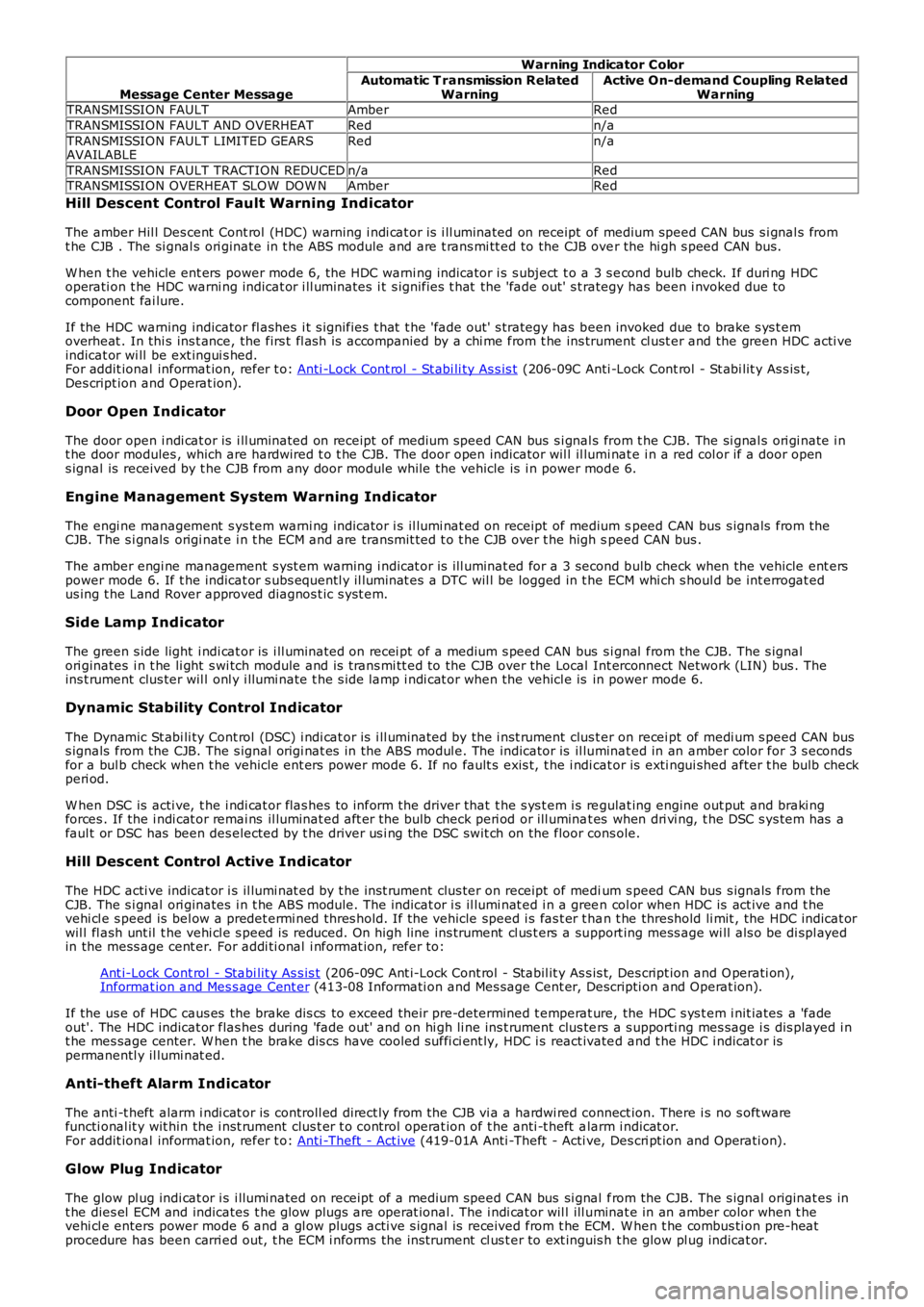
Message Center Message
Warning Indicator Color
Automatic T ransmission RelatedWarningActive On-demand Coupling RelatedWarningTRANSMISSION FAULTAmberRed
TRANSMISSION FAULT AND OVERHEATRedn/a
TRANSMISSION FAULT LIMITED GEARSAVAILABLERedn/a
TRANSMISSION FAULT TRACTION REDUCEDn/aRedTRANSMISSION OVERHEAT SLOW DOW NAmberRed
Hill Descent Control Fault Warning Ind icator
The amber Hil l Des cent Cont rol (HDC) warning i ndi cat or is i ll uminated on receipt of medium speed CAN bus s i gnal s fromt he CJB . The si gnal s ori ginate in t he ABS module and are t rans mi tt ed to the CJB over the hi gh s peed CAN bus.
W hen t he vehicle ent ers power mode 6, the HDC warni ng indicator i s s ubject t o a 3 s econd bulb check. If duri ng HDCoperati on t he HDC warni ng indicat or i ll uminates i t s ignifies t hat the 'fade out' s t rategy has been i nvoked due tocomponent fai lure.
If the HDC warning indicator fl ashes i t s ignifies t hat t he 'fade out' s trategy has been invoked due to brake s ys t emoverheat . In thi s ins t ance, the firs t fl as h is accompanied by a chi me from t he ins trument cl ust er and the green HDC acti veindicat or wi ll be ext ingui s hed.For addit ional informat ion, refer t o: Anti -Lock Cont rol - St abi li ty As s is t (206-09C Anti -Lock Cont rol - St abi lit y As s is t,Des cript ion and Operat ion).
Door Open Indicator
The door open i ndi cat or is i ll uminated on receipt of medium speed CAN bus s i gnal s from t he CJB. The si gnal s ori gi nate i nt he door modules , which are hardwired t o t he CJB. The door open indicator wil l il lumi nat e i n a red col or if a door opens ignal is received by t he CJB from any door module while the vehicle is i n power mode 6.
Engine Management System Warning Indicator
The engi ne management s ys tem warni ng indicator i s il lumi nat ed on receipt of medium speed CAN bus s ignals from theCJB. The s i gnals origi nat e i n t he ECM and are transmit ted t o t he CJB over t he high speed CAN bus .
The amber engi ne management s yst em warning i ndicat or is ill uminat ed for a 3 second bulb check when the vehicle ent erspower mode 6. If t he indicat or s ubs equentl y il lumi nat es a DTC wil l be logged in t he ECM whi ch s houl d be int errogat edus ing t he Land Rover approved diagnos t ic s yst em.
Side Lamp Indicator
The green s ide light i ndi cat or is i ll uminated on recei pt of a medium s peed CAN bus si gnal from the CJB. The s ignalori ginates i n t he li ght s wi tch module and is t rans mi tt ed to the CJB over the Local Int erconnect Network (LIN) bus . Theins t rument clus ter wil l onl y i llumi nate t he s ide lamp i ndi cat or when the vehicl e is in power mode 6.
Dynamic Stability Control Indicator
The Dynamic St abi li ty Cont rol (DSC) i ndi cat or is i ll uminated by the i nst rument clus ter on recei pt of medi um s peed CAN buss ignals from the CJB. The s ignal origi nat es in the ABS modul e. The indicator is il luminat ed in an amber color for 3 s econdsfor a bul b check when t he vehicle ent ers power mode 6. If no fault s exis t, t he i ndi cat or is exti ngui shed after t he bulb checkperi od.
W hen DSC is acti ve, t he i ndi cat or flas hes t o inform the driver that t he s ys t em i s regulat ing engine out put and braki ngforces . If the i ndi cat or remai ns il luminat ed aft er the bulb check peri od or ill uminat es when dri vi ng, t he DSC s ys tem has afaul t or DSC has been des elected by t he driver us i ng the DSC swit ch on the floor cons ole.
Hill Descent Control Active Indicator
The HDC acti ve indicat or i s il lumi nat ed by t he ins t rument clus ter on receipt of medium s peed CAN bus s ignals from theCJB. The s i gnal ori ginates i n t he ABS module. The indicat or i s il lumi nat ed i n a green col or when HDC is act ive and t hevehi cl e s peed is bel ow a predet ermi ned thres hold. If the vehicle speed i s fas t er t han t he threshold li mit , the HDC indicat orwil l fl ash unt il t he vehi cl e s peed is reduced. On high line ins trument cl us t ers a support ing mess age wi ll als o be di spl ayedin the mess age cent er. For addi ti onal i nformat ion, refer to:
Ant i-Lock Cont rol - Stabi lit y As s is t (206-09C Ant i-Lock Cont rol - Stabil it y As s is t, Des cript ion and O perati on),Informat ion and Mes s age Cent er (413-08 Informati on and Mes sage Cent er, Descripti on and Operat ion).
If the us e of HDC caus es the brake di s cs to exceed their pre-determined t emperat ure, the HDC s ys t em i nit iates a 'fadeout'. The HDC indicat or flas hes during 'fade out ' and on hi gh li ne ins t rument clus ters a s upporti ng mes sage i s dis played i nt he mes sage center. W hen t he brake dis cs have cooled suffi ci ent ly, HDC i s react ivated and t he HDC i ndicat or ispermanentl y il lumi nat ed.
Anti-theft Alarm Indicator
The anti -t heft alarm i ndi cat or is controll ed direct ly from the CJB vi a a hardwi red connect ion. There i s no s oft warefuncti onal it y wit hin the i nst rument clus t er t o control operat ion of t he anti -t heft alarm i ndicat or.For addit ional informat ion, refer t o: Anti -Theft - Act ive (419-01A Anti -Theft - Acti ve, Des cri pt ion and Operati on).
Glow Plug Indicator
The glow pl ug indi cat or i s i llumi nated on recei pt of a medium speed CAN bus si gnal from the CJB. The s ignal originat es int he dies el ECM and indicates t he glow plugs are operat ional. The i ndi cat or wil l ill uminat e in an amber color when t hevehi cl e enters power mode 6 and a gl ow plugs acti ve s ignal is received from t he ECM. W hen t he combus ti on pre-heatprocedure has been carri ed out, t he ECM i nforms the ins trument cl us t er to ext inguis h t he glow pl ug indicat or.
Page 1820 of 3229
If the el ect rolyt e level is l ow, top-up usi ng dis t ill ed water.
Maint enance free and Valve Regulat ed (AGM) bat teries are s eal ed and therefore cannot be topped up.
CHARGING SYSTEM TEST AND DIAGNOSIS
For al l vehi cl es , refer to the Chargi ng Syst em - Diagnos i s and Tes t ing i n s ect ion 414-00 of the W orks hop Manual.
VEHICLE QUIESCENT CURRENT TESTING
• NOTE: On vehicles fit t ed wit h a Bat tery Monit oring Sys t em (BMS), t he diagnos t ic routi ne for quies cent drai n t es t ing i nt he approved di agnos ti c s ys t em s hould be ut il ized.
• NOTE: If a cus t omer compl ains of a vehicle bat tery that dis charges cont inuousl y or when left for a prolonged period oft ime, it is recommended t hat a quies cent drai n tes t i s performed as des cribed below.
• NOTE: The batt ery drain s hould be meas ured usi ng an approved diagnos t ic s ys tem or a Digi tal Mult i-Meter (DVOM).
The vehi cl e s houl d be i n t he locked/armed st ate (for example vehi cl e alarm full y armed), al l doors , engine and luggagecompartment l ids are open and lat ched (s o as t o appear clos ed from an electrical point of view). The t es t s houl d t akeplace aft er the vehicle has ent ered s hutdown mode. The t ime taken for this to occur after t he igni ti on is s wi tched offvaries according t o model - Refer t o Quies cent Drain in s ecti on 414-00 of the W orks hop Manual .
• NOTE: W hen t he vehicle i s armed, t he effect of t he s ecurit y s ys t em Li ght Emi tt ing Diode (LED) flas hing i s to caus e apuls ati on in the meas ured current drain. In t hi s case, eit her the average current should be taken (usi ng a Di gi tal Mul ti -Meter (DVOM) wi th an averagi ng s ys t em) or the current reading t aken, ignori ng t he bri ef hi gh current peaks .
EQUIPMENT
Approved diagnos t ic s ys tem wit h current probe or Digit al Mul ti -Met er (DVOM) wit h current probe.
METHOD OF MEASUREMENT
Using an Approved Diagnostic System
1. Swit ch off all elect rical loads and ensure t hat t he i gni ti on is off.
2. Connect the current probe t o t he approved di agnos ti c s yst em.
3. Calibrate t he probe.
4. Ins t al l a clamp around the bat tery lead/junct ion box l ead.
5. Go t o t he Quies cent Current Tes t ing s ect ion.
Using a Digital Multi-Meter (DVOM)
• NOTE: Do not us e an i n-li ne DVOM to meas ure the qui escent drain on vehi cl es fi tt ed wi th an el ect roni c throt t le. Thecurrent exceeds t he maximum amount the fus e in the DVOM is capable of handling.
1. Swit ch off all elect rical loads and ensure t hat t he i gni ti on is off.
2. Connect the current probe t o t he DVOM.
3. Calibrate t he probe.
4. Ins t al l a clamp around the bat tery lead/junct ion box l ead.
5. Go t o t he fol lowing Qui escent Current Tes ti ng s ect ion.
QUIESCENT CU RRENT TESTING
1. Swit ch ignit ion t o ‘on’ or s elect ignit ion mode i n keyles s vehi cl es and s wit ch to ‘off’ (do not crank).
2. Remove key from i gni ti on s wit ch (where appl icabl e).
3. Open and lat ch all doors , hood and l uggage compart ment li d.
4. Lock t he vehi cle us ing t he remote funct ion on the remote hands et. (Single lock onl y t o avoi d volumet ri c alarm arming).
5. Remove any ot her pot enti al el ect ri cal drai ns such as acces s ori es plugged into acces sory s ockets .
6. Record the amperage readings after t he shut down period. The model specific Amperage readings for quies cent drain arereferenced in Qui escent Drain in secti on 414-00 of t he W orks hop Manual
7. Record the fi nal readi ng on the bat tery report form Appendi x B.
• NOTE: The preferred method of t est ing foll owing an exces s ive current cons umpti on fi gure i s t o use a current probearound i ndi vi dual junct ion box l eads t o t he various s us pect ed ci rcuit s t o ident ify a potent ial caus e. Thi s is in preference t ot he old met hod of removing fus es for t he fol lowing reasons :
Many modules t ake a cons i derabl e t ime to power down. Each t ime a fuse is removed and re-fi tt ed, t he quies centdrai n current may t ake an extended peri od of ti me t o ret urn to normal (t ypi cal ly up to 45 minut es ).The drai n may be caused by a module remaini ng act ive and prevent ing t he quies cent drai n from reduci ng to normallevels .The drai n may be caused by a rel ay winding that is act ivated. Pulli ng t he fus e can all ow t his t o ‘res et ’ and the drainwil l be los t and go un-di agnos ed.