2006 LAND ROVER FRELANDER 2 catalytic converter
[x] Cancel search: catalytic converterPage 40 of 3229
s tored on open ground coul d eit her leak or have contami nati ng subs tances was hed off them that would cont aminate theland. Always s tore t hes e materi als i n s uit abl e s kips or s imi larly robus t cont ainers .
Legal compliance
Some s it es may have a di scharge cons ent for effl uent di scharge t o t he foul drai n for a car was h et c. It is ess enti al t o knowt he types of effluent which are al lowed t o be di scharged i nto t he drai n and t o check t he res ult s of any monit ori ng carri edout by the W ater Company.
W here paint s praying operat ions are carried out i t may be necess ary to apply to the Local Aut horit y for an ai r emis s ionsli cence t o operate the pl ant . If such a licence is necess ary, addit ional precaut ions wil l be neces s ary t o comply wi th therequirements and t he resul ts of any air quali ty moni toring mus t be checked regul arl y.
Checkli s t
Alw ays adhere to the following:
Know what legal cons ents and l icences apply t o t he operat ions.
Check t hat the emis s ions and dis charges compl y wit h l egal requi rements .
Waste Management
Pollut ion can be reduced by careful handli ng, s t orage and dis posal of all was te materials that occur on s it es. Legis lat ionmakes it i ll egal t o dis pose of was t e mat eri al s other t han to licens ed wast e carriers and dis pos al s it es.
This means t hat it i s neces sary t o not onl y know what the wast e mat eri al s are but als o to have the neces s arydocument at ion and licences .
Handl ing and s t orage of was te
Ensure t hat was t e mat erial s are not poured down the drai n or on t o s oil and are st ored in s uch a way t hat they do notes cape on t o l and or soi l.
All was te mus t be s egregat ed int o i ndi vi dual t ypes e.g. oils , met als , bat t eries , s crap component s etc. This wi ll prevent anyreacti on between di fferent materials and as s is t i n dis posal .
Dis pos al of was te
Dis pos e of wast e i n accordance wi th t he followi ng guidelines :
Fuel, hydraulic fluid, anti-freeze and oil: Keep s eparate and dis pos e of t o s peci alis t contract ors .
Refrigerant: Col lect in s peci ali st equipment and reus e.
Detergents: Safe to pour down t he foul drai n if di luted.
Paint, thinners: Keep separat e and dis pose of to speciali st contract or.
Components: Return t o s uppl ier for refurbi shment or dis as sembl e and reus e any s uit able part s . Dis pose ofremai nder i n ordi nary was te.
Small parts: Reuse any sui table parts , dis pos e of the remainder in ordinary was t e.
Metals: Can be s old i f separat e from general was t e.
T yres: Keep s eparate and di s pos e of t o s peci al is t cont ract or. DO NO T att empt to dis pos e of t yres by burni ng.
Components/materials containing asbestos: Keep separat e and dis pose of to speciali st contract or.
Oil and fuel wastes (e.g. rags, used spill kit material): Keep s eparate and dis pos e of t o s peci alis t contract ors .
Air filters: Keep s eparat e and dis pose of to s peciali st contract ors .
Rubber/plastics: Dis pos e of i n ordi nary was te.
Hoses: Di s pos e of i n ordinary was te.
Batteries: Keep separat e and dis pose of to speciali st contract ors .
Air bags - DANGER EXPLOSIVES: Keep s eparate and dis pos e of t o s peci alis t contract ors .
Electrical components: Return to suppli er for refurbis hment or dis ass emble and reus e any s uit abl e components .Dis pos e of remai nder in ordinary wast e.
Catalytic converters: May be s ol d i f kept s eparate from general wast e.
Packaging: Compact/recycl e as much as pos s ible and di s pos e of i n ordinary was te.
Office/paper waste: Recycl e paper and t oner and i nk cart ridges , dis pos e of remainder in ordinary was t e.
Noise
Car alarm t es t ing, panel beati ng, runni ng engi nes , us ing ai r tools et c. are operat ions which i nvariably produce a largeamount of noi se. The l ocati on of s uch act ivit ies and als o the t ime of day must be carefull y cons idered havi ng regard to theproximit y of hous es s chools et c.
Page 1515 of 3229
5-Gasket
6-Tailpi pe fi nis her (opti onal )
7-Mount ing rubber (6 off)8-Rear muffler
9-Cent re muffler
10-Flange11-Bracket
12-Catalyt ic converter (2 off)
13-Flange14-Catalyt ic converter (2 off)
15-Exhaus t manifol d gas ket s
OVERVIEW
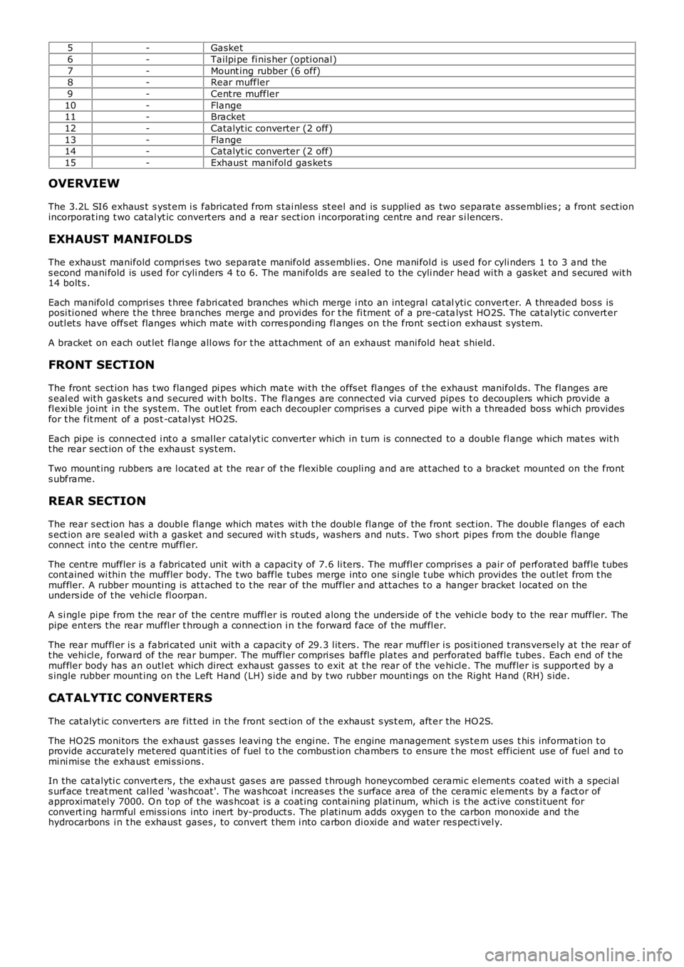
The 3.2L SI6 exhaus t s yst em i s fabricated from s tai nl ess st eel and is s upplied as two separat e as sembl ies ; a front s ect ionincorporat ing t wo catal yt ic convert ers and a rear sect ion i ncorporat ing centre and rear s i lencers.
EXHAUST MANIFOLDS
The exhaus t manifold compri s es two separat e manifold as s embli es . One mani fol d is us ed for cyli nders 1 t o 3 and thes econd mani fold is us ed for cyli nders 4 t o 6. The manifolds are s eal ed to the cyli nder head wi th a gas ket and s ecured wit h14 bolt s .
Each manifol d compri ses t hree fabri cat ed branches whi ch merge i nto an int egral cat alyti c convert er. A threaded bos s isposi ti oned where t he t hree branches merge and provi des for t he fi tment of a pre-catalys t HO2S. The cat alyti c convert eroutl et s have offs et flanges which mat e wi th corres pondi ng fl anges on t he front s ect ion exhaus t s ys tem.
A bracket on each out let flange all ows for t he att achment of an exhaus t mani fold heat s hield.
FRONT SECTION
The front sect ion has t wo flanged pi pes which mat e wi th the offs et fl anges of t he exhaus t manifol ds. The flanges ares eal ed wit h gas ket s and s ecured wit h bolt s . The fl anges are connected vi a curved pipes t o decouplers which provide afl exi ble joint i n the sys tem. The out let from each decoupl er compris es a curved pipe wit h a t hreaded bos s whi ch providesfor t he fit ment of a pos t -catal ys t HO2S.
Each pi pe is connect ed i nt o a smal ler catalyt ic converter whi ch in t urn is connected to a doubl e fl ange which mat es wit ht he rear s ect ion of t he exhaus t s ys t em.
Two mount ing rubbers are l ocat ed at the rear of the flexible coupli ng and are at t ached t o a bracket mounted on the fronts ubframe.
REAR SECTION
The rear s ect ion has a doubl e fl ange which mat es wit h t he doubl e fl ange of the front s ect ion. The doubl e flanges of eachs ect ion are s eal ed wi th a gas ket and s ecured wit h s tuds , washers and nuts . Two s hort pipes from the double fl angeconnect int o the cent re muffl er.
The cent re muffler is a fabricated unit wit h a capaci ty of 7.6 li ters. The muffl er compris es a pair of perforat ed baffle t ubescont ained wi thin the muffler body. The t wo baffle tubes merge into one s ingle t ube which provi des the out let from t hemuffler. A rubber mounti ng is at t ached t o t he rear of the muffler and att aches t o a hanger bracket l ocat ed on theunders ide of t he vehi cl e fl oorpan.
A s i ngl e pipe from t he rear of the centre muffl er is rout ed along t he unders ide of the vehi cl e body to the rear muffler. Thepipe ent ers t he rear muffl er t hrough a connect ion i n t he forward face of the muffl er.
The rear muffl er i s a fabri cat ed uni t wit h a capacit y of 29.3 l it ers . The rear muffler i s pos i ti oned t rans vers ely at t he rear oft he vehi cl e, forward of the rear bumper. The muffler compri ses baffl e plat es and perforated baffle tubes . Each end of t hemuffler body has an outl et which direct exhaus t gas ses to exit at t he rear of t he vehi cl e. The muffler is support ed by as ingle rubber mount ing on t he Left Hand (LH) s ide and by t wo rubber mounti ngs on the Right Hand (RH) s ide.
CATALYTIC CONVERTERS
The cat alyt ic converters are fit t ed in t he front s ect ion of t he exhaus t s ys t em, aft er the HO2S.
The HO2S moni tors the exhaust gas s es leavi ng t he engi ne. The engine management s ys t em us es t hi s informat ion t oprovide accuratel y met ered quant it ies of fuel t o t he combus t ion chambers t o ens ure the mos t efficient us e of fuel and t omi ni mi se the exhaus t emi s si ons .
In the cat alyti c convert ers , t he exhaus t gas es are pas s ed t hrough honeycombed ceramic el ement s coated wi th a s peci als urface t reat ment cal led 'was hcoat '. The was hcoat i ncreas es t he s urface area of the cerami c element s by a fact or ofapproximat el y 7000. O n top of t he was hcoat i s a coat ing cont ai ning plat inum, whi ch is t he act ive cons ti tuent forconvert ing harmful emi ss i ons into inert by-product s. The pl at inum adds oxygen t o the carbon monoxi de and thehydrocarbons i n t he exhaus t gases , to convert t hem i nto carbon di oxi de and water respecti vel y.
Page 1521 of 3229
Publi s hed: 11-May-2011
Exhaust System - I6 3.2L Petrol - Catalytic Converter
Removal and Inst all ati on
Special T ool(s) 310-121
W rench, H02S
Removal
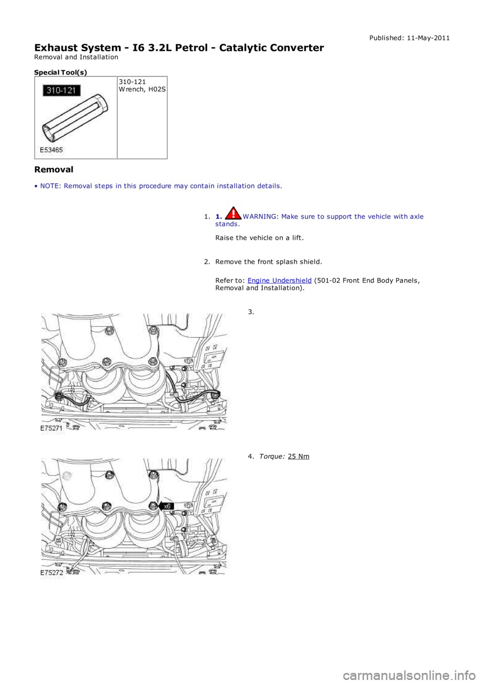
• NOTE: Removal s t eps in t his procedure may cont ain i nst all ati on det ail s.
1. W ARNING: Make sure t o s upport the vehicle wit h axle
s tands .
Rais e t he vehicle on a li ft .
1.
Remove t he front spl as h s hiel d.
Refer t o: Engi ne Unders hi eld (501-02 Front End Body Panel s ,
Removal and Ins tall ati on).
2. 3.
T orque:
25 Nm 4.
Page 1529 of 3229
12-'V' cl amp and gas ket
13-Turbocharger (ref only)
OVERVIEW
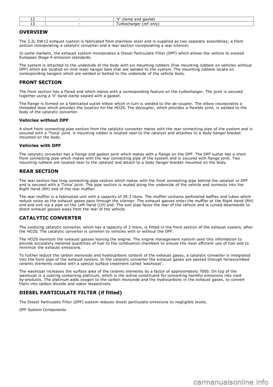
The 2.2L DW 12 exhaus t s ys t em i s fabricated from s tainl ess st eel and i s s uppl ied as two s eparat e as sembl ies ; a fronts ect ion i ncorporati ng a catalyt ic converter and a rear sect ion i ncorporat ing a rear s il encer.
In s ome market s , the exhaus t s yst em incorporates a Dies el Parti cul ate Fi lt er (DPF) which all ows the vehicl e to exceedEuropean Stage 4 emis s ion s tandards .
The s ys t em i s att ached to t he unders ide of t he body wit h s ix mount ing rubbers (fi ve mount ing rubbers on vehicles wi thoutDPF) which are locat ed on mild st eel hanger bars t hat are wel ded to t he s yst em. The mounti ng rubbers locat e oncorres pondi ng hangers which are welded or bolt ed to the unders i de of the vehicle body.
FRONT SECTION
The front sect ion has a flared end which mat es wit h a corres ponding feature on t he turbocharger. The joint i s s ecuredt oget her us ing a 'V' band cl amp s ealed wi th a gasket .
The fl ange is formed on a fabricated out let elbow whi ch in turn is wel ded to the de-coupler. The elbow i ncorporat es at hreaded bos s whi ch provi des the locat ion for the HO2S. The decoupl er, which provi des a fl exi ble joint, i s welded t o t hebody of the catal yt ic convert er.
Vehicles without DPF
A s hort front connecti ng pipe s ecti on from t he catalyt ic converter mat es wit h t he rear connect ing pipe of t he s yst em and iss ecured wit h a 'Torca' joint. A mounti ng rubber is l ocat ed near t o t he cat alys t and att aches t o a body hanger bracketmounted on the body.
Vehicles with DPF
The cat alyt ic converter has a flange and gasket joi nt which mat es wit h a fl ange on the DPF. The DPF outl et has a s hortfront connect ing pi pe which mat es wi th t he rear connect ing pipe of t he s yst em and is s ecured wi th flange joint. Twomounti ng rubbers are l ocated near t o t he cat alys t and att ach to a body hanger bracket mount ed on the body.
REAR SECTION
The rear s ect ion has l ong connecti ng pipe s ect ion whi ch mat es wit h t he front connecting pi pe behi nd the cat alyst or DPFand is secured wi th a 'Torca' joi nt. The pipe secti on is routed al ong the unders i de of the vehicle and connect s int o t heRight Hand (RH) end of t he rear muffl er.
The rear muffl er i s a fabri cat ed uni t wit h a capacit y of 29.3 l it ers . The muffler cont ains perforat ed baffl es and t ubes whi chreduce nois e as t he exhaus t gases pas s t hrough the si lencer. The exhaus t gas s es enter t he muffler at t he Right Hand (RH)end and exit via a pipe on t he Left Hand (LH) end. The exit pi pe faces the rear of the vehicle and is curved downwards t odirect exhaus t gas ses away from t he rear of the vehicle.
CATALYTIC CONVERTER
The oxidizing cat al yti c convert er, which has a capacit y of 2 li ters, i s fit ted i n t he front secti on of the exhaust sys tem, aftert he HO2S. The cat al yti c convert er is common t o vehicles wi th or wit hout t he DPF.
The HO2S moni tors the exhaust gas s es leavi ng t he engi ne. The engine management s ys t em us es t hi s informat ion t oprovide accuratel y met ered quant it ies of fuel t o t he combus t ion chambers t o ens ure the mos t efficient us e of fuel and t omi ni mi ze the exhaus t emi s si ons .
To furt her reduce t he carbon monoxi de and hydrocarbons content of t he exhaus t gas es , a catalyt ic converter i s int egratedint o t he front pi pe of the exhaust sys tem. In t he catalyt ic converter t he exhaus t gases are pass ed t hrough honeycombedceramic el ements coated wit h a s peci al surface t reatment call ed 'was hcoat '.
The was hcoat increas es the surface area of t he cerami c elements by a fact or of approximat ely 7000. On t op of thewas hcoat is a coat ing contai ni ng plat inum, which i s t he act ive const it uent for convert ing harmful emi ss i ons i nto inertby-products . The plat inum adds oxygen to t he carbon monoxide and t he hydrocarbons in t he exhaus t gases , t o convertt hem int o carbon dioxide and wat er res pect ively.
DIESEL PARTICULATE FILTER (if fitted)
The Dies el Parti cul ate Fi lt er (DPF) s ys t em reduces dies el parti cul at e emi s si ons to negl igible levels .
DPF Syst em Components
Page 1535 of 3229
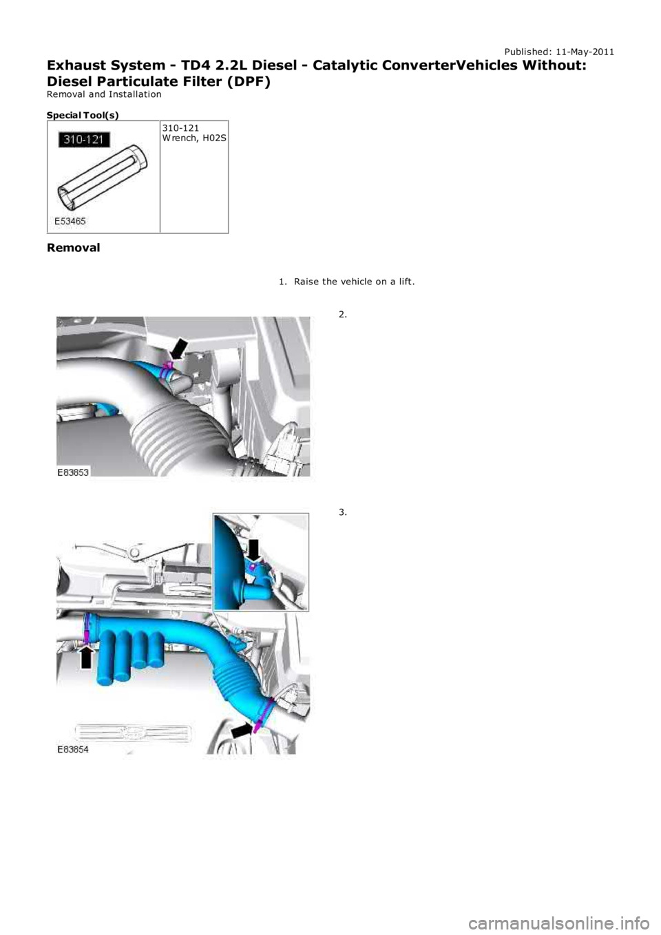
Publi s hed: 11-May-2011
Exhaust System - TD4 2.2L Diesel - Catalytic ConverterVehicles Without:
Diesel Particulate Filter (DPF)
Removal and Inst all ati on
Special T ool(s)
310-121W rench, H02S
Removal
Rais e t he vehicle on a li ft .1.
2.
3.
Page 1538 of 3229
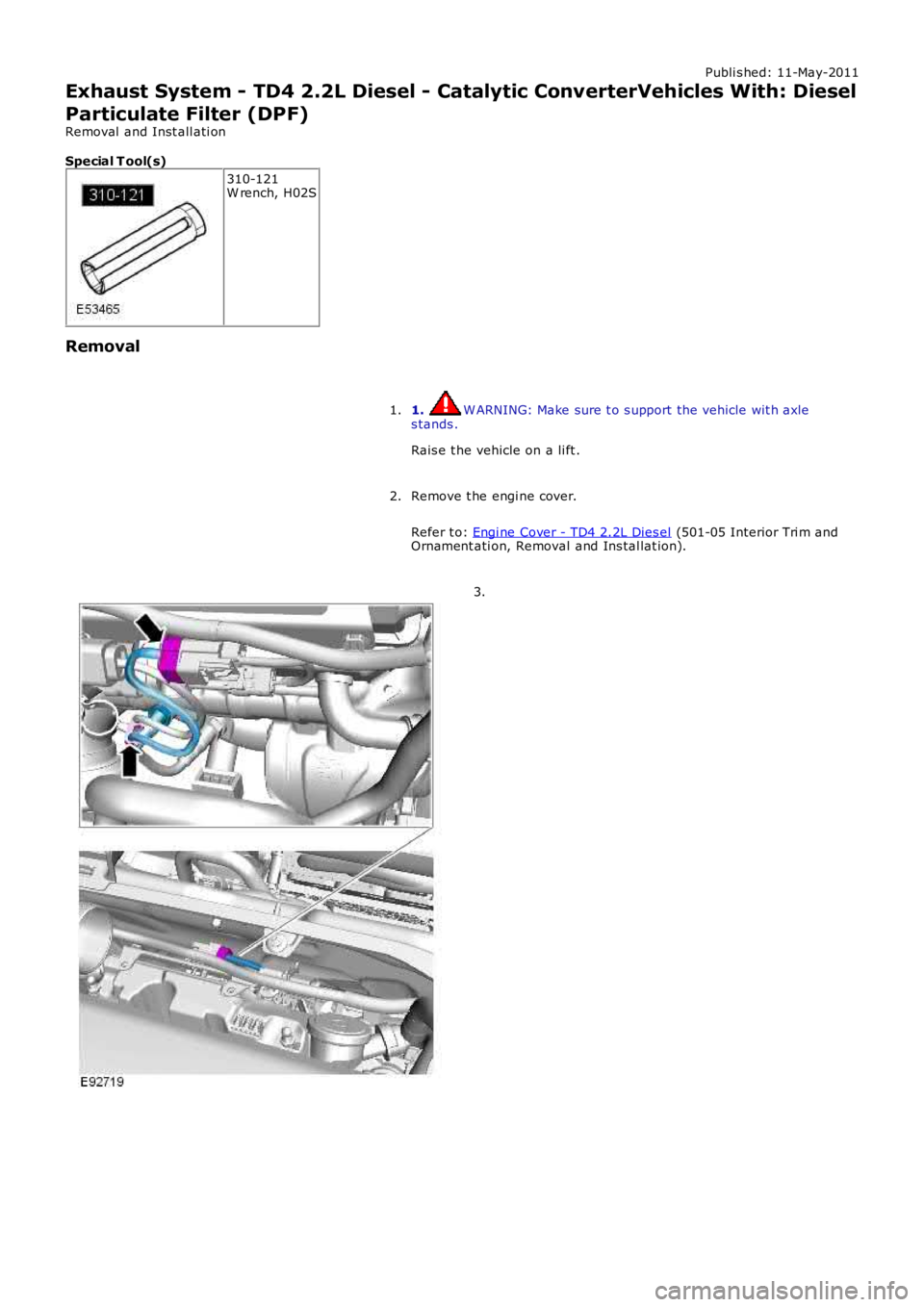
Publi s hed: 11-May-2011
Exhaust System - TD4 2.2L Diesel - Catalytic ConverterVehicles With: Diesel
Particulate Filter (DPF)
Removal and Inst all ati on
Special T ool(s)
310-121W rench, H02S
Removal
1. W ARNING: Make sure t o s upport the vehicle wit h axles tands .
Rais e t he vehicle on a li ft .
1.
Remove t he engi ne cover.
Refer t o: Engi ne Cover - TD4 2.2L Dies el (501-05 Interior Tri m andOrnament ati on, Removal and Ins tal lat ion).
2.
3.
Page 2703 of 3229
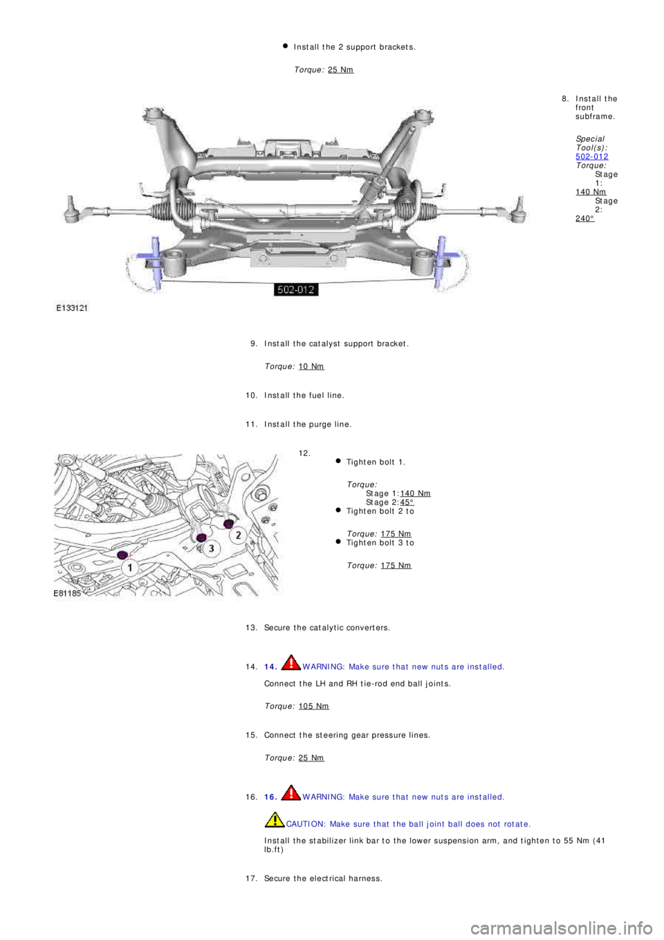
St a g e
1:
St a g e
2:
St a g e 1:
St a g e 2: Install the 2 support brackets.
Torque: 25 Nm
Install the
front
subframe.
Sp e c i a l
T ool (s ):
502-012
Torque:
140 Nm
240°
8.
Install the catalyst support bracket.
Torque: 10 Nm
9.
Install the fuel line. 10.
Install the purge line. 11.
Tighten bolt 1.
Torque:
140 Nm
45°Tighten bolt 2 to
Torque: 175 Nm
Tighten bolt 3 to
Torque: 175 Nm
12.
Secure the catalytic converters. 13.
14.
WARNING: Make sure that new nuts are installed.
Connect the LH and RH tie-rod end ball joints.
Torque: 105 Nm14.
Connect the steering gear pressure lines.
Torque: 25 Nm
15.
16.
WARNING: Make sure that new nuts are installed.
CAUTION: Make sure that the ball joint ball does not rotate.
Install the stabilizer link bar to the lower suspension arm, and tighten to 55 Nm (41
lb.ft) 16.
Secure the electrical harness. 17.
Page 2740 of 3229
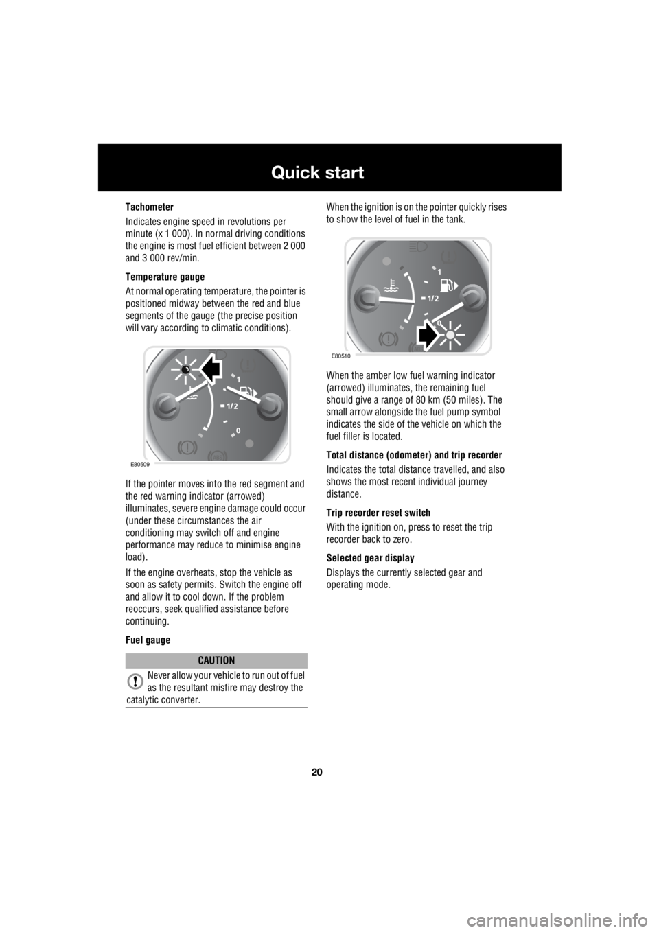
20
Quick start
L
Tachometer
Indicates engine spee d in revolutions per
minute (x 1 000). In normal driving conditions
the engine is most fuel efficient between 2 000
and 3 000 rev/min.
Temperature gauge
At normal operating temperature, the pointer is
positioned midway between the red and blue
segments of the gauge (the precise position
will vary according to climatic conditions).
If the pointer moves into the red segment and
the red warning indicator (arrowed)
illuminates, severe engi ne damage could occur
(under these circumstances the air
conditioning may switch off and engine
performance may reduce to minimise engine
load).
If the engine overheats, stop the vehicle as
soon as safety pe rmits. Switch the engine off
and allow it to cool down. If the problem
reoccurs, seek qualified assistance before
continuing.
Fuel gauge When the ignition is on the pointer quickly rises
to show the level of fuel in the tank.
When the amber low fuel warning indicator
(arrowed) illuminates, the remaining fuel
should give a range of 80 km (50 miles). The
small arrow alongside th e fuel pump symbol
indicates the side of the vehicle on which the
fuel filler is located.
Total distance (odometer) and trip recorder
Indicates the total distance travelled, and also
shows the most recent individual journey
distance.
Trip recorder reset switch
With the ignition on, press to reset the trip
recorder back to zero.
Selected gear display
Displays the currently selected gear and
operating mode.
CAUTION
Never allow your vehicl e to run out of fuel
as the resultant misfire may destroy the
catalytic converter.
E80509
E80510