2006 LAND ROVER FRELANDER 2 oil temperature
[x] Cancel search: oil temperaturePage 45 of 3229
All ow t he vehi cl e t o coas t and note any tendency t o pull t o one s ide, or evi dence t hat the brakes are binding.
Aft er s topping t he vehi cl e (not immedi at ely after a period of heavy braking), careful ly check the brake temperat ure. A di s cwhich feel s appreciably hot ter t han the ot hers , could indicate that t he pads on that dis c are binding.
Aft er compl eti on of the t es t, check for:
Oil , cool ant , hydraul ic, air and fuel l eaks .Abnormal temperature of any movi ng components or as s embli es , e.g. wheel hubs , t rans mis s ion et c., which mightindicat e over t ight nes s or lack of lubricati on.
Rolling Road Testing
Four-Wheel Rolling Road
CAUTION: W hen ut il is ing a four-wheel roll ing road for t est ing, ensure all relevant healt h and s afet y requirements areadhered t o.
Provided t hat front and rear roll ers are rot ati ng at identi cal s peeds and t hat normal works hop s afety st andards are appli ed,t here is no s peed res tricti on during tes ti ng except any that may apply to the t ires.
Ensure t hat t he parking brake is releas ed pri or t o engaging rol ler dri ving mechani s m.
Two-Wheel Rolling Road
CAUTION: On no account s hould an at t empt be made t o carry out any form of tes t ing on a two-wheel rolli ng road.
Page 603 of 3229
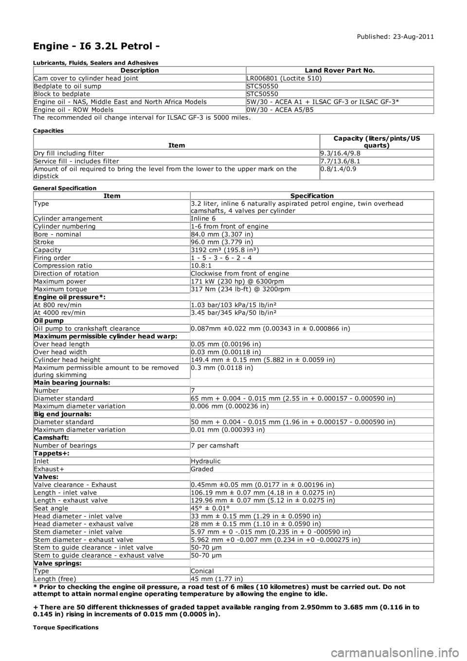
Publi s hed: 23-Aug-2011
Engine - I6 3.2L Petrol -
Lubricants, Fluids, Sealers and AdhesivesDescriptionLand Rover Part No.
Cam cover to cyli nder head jointLR006801 (Loct it e 510)
Bedplate to oi l s umpSTC50550Block t o bedpl ateSTC50550
Engine oil - NAS, Mi ddl e Eas t and Nort h Africa Models5W /30 - ACEA A1 + ILSAC GF-3 or ILSAC GF-3*
Engine oil - ROW Models0W /30 - ACEA A5/B5The recommended oil change i nterval for ILSAC GF-3 is 5000 mi les .
C apacities
ItemCapacity (liters/pints/USquarts)
Dry fi ll i ncludi ng fi lt er9.3/16.4/9.8
Service fil l - includes fi lt er7.7/13.6/8.1Amount of oil required t o bri ng the level from the lower to the upper mark on thedips t ick0.8/1.4/0.9
General Specification
ItemSpecificationType3.2 li ter, inli ne 6 nat urall y aspi rat ed pet rol engine, twi n overheadcams haft s, 4 val ves per cylinderCyli nder arrangementInli ne 6
Cyli nder numberi ng1-6 from front of engine
Bore - nominal84.0 mm (3.307 in)St roke96.0 mm (3.779 in)
Capaci ty3192 cm³ (195.8 i n³)
Firing order1 - 5 - 3 - 6 - 2 - 4Compres s ion rati o10.8:1
Di recti on of rotat ionCl ockwis e from front of engi ne
Maximum power171 kW (230 hp) @ 6300rpmMaximum t orque317 Nm (234 lb-ft ) @ 3200rpm
Engine oil pressure*:
At 800 rev/min1.03 bar/103 kPa/15 lb/in²At 4000 rev/min3.45 bar/345 kPa/50 lb/in²
Oil pump
Oi l pump to cranks haft clearance0.087mm ±0.022 mm (0.00343 i n ± 0.000866 i n)Maximum permissible cylinder head w arp:
Over head length0.05 mm (0.00196 i n)
Over head widt h0.03 mm (0.00118 i n)Cyli nder head height149.4 mm ± 0.15 mm (5.882 in ± 0.0059 i n)
Maximum permi s si ble amount t o be removedduri ng s ki mmi ng0.3 mm (0.0118 in)
Main bearing journals:
Number7
Di amet er s tandard65 mm + 0.004 - 0.015 mm (2.55 in + 0.000157 - 0.000590 in)Maximum diamet er variat ion0.006 mm (0.000236 in)
Big end journals:
Di amet er s tandard50 mm + 0.004 - 0.015 mm (1.96 in + 0.000157 - 0.000590 in)Maximum diamet er variat ion0.01 mm (0.000393 i n)
Camshaft:
Number of bearings7 per cams haftT appets+:
InletHydrauli c
Exhaus t +GradedValves:
Valve clearance - Exhaus t0.45mm ±0.05 mm (0.0177 in ± 0.00196 in)
Lengt h - i nlet valve106.19 mm ± 0.07 mm (4.18 in ± 0.0275 i n)Lengt h - exhaus t valve129.96 mm ± 0.07 mm (5.12 in ± 0.0275 i n)
Seat angl e45° ± 0.01°
Head diamet er - inlet valve33 mm ± 0.15 mm (1.29 in ± 0.0590 i n)Head diamet er - exhaus t val ve28 mm ± 0.15 mm (1.10 in ± 0.0590 i n)
St em diamet er - inlet valve5.97 mm + 0 -.015 mm (0.235 in + 0 -000590 i n)
St em diamet er - exhaus t val ve5.962 mm +0 -0.007 mm (0.234 in +0 -0.000275 i n)St em t o guide clearance - i nlet val ve50-70 µm
St em t o guide clearance - exhaus t valve50-70 µm
Valve springs:TypeConical
Lengt h (free)45 mm (1.77 in)
* Prior to checking the engine oil pressure, a road test of 6 miles (10 kilometres) must be carried out. Do notattempt to attain normal engine operating temperature by allowing the engine to idle.
+ T here are 50 different thicknesses of graded tappet available ranging from 2.950mm to 3.685 mm (0.116 in to0.145 in) rising in increments of 0.015 mm (0.0005 in).
Torque Specifications
Page 649 of 3229
det ermi ne the source of oi l cons umpt ion such as valves , pi s ton rings or other areas .
7. Check valve guides for exces si ve gui de clearance. Ins tall new val ve st em seals aft er verifyi ng val ve guideclearance.7.
8. W orn or damaged i nternal engine component s can caus e exces s ive oi l cons umpti on. Small depos it s of oi l on t het ips of t he s park plugs can be a cl ue t o int ernal oi l cons umpti on.8.
Intake Manifold Vacuum Test
Bri ng t he engi ne to normal operati ng temperature. Connect a vacuum gauge or equi val ent t o t he i nt ake manifold. Run theengi ne at t he specified i dle s peed.
The vacuum gauge s hould read bet ween 51-74 kPa (15-22 i n-Hg) dependi ng upon the engine condit ion and t he alt it ude atwhich t he t es t i s performed. Subt ract 4.0193 kPa (1 in-Hg) from t he s peci fi ed reading for every 304.8 m (1,000 feet ) ofelevati on above s ea l evel .
The reading should be st eady. As necess ary, adjus t t he gauge damper cont rol (where us ed) if t he needl e is fl ut t eringrapi dl y. Adjust damper unti l needle moves eas il y wi thout exces si ve fl utt er.
Interpreting Vacuum G auge Readings
A careful s t udy of the vacuum gauge reading whi le t he engine i s idli ng wi ll help pi npoint t rouble areas. Al ways conductother appropri at e t es ts before arrivi ng at a final di agnos ti c deci s ion. Vacuum gauge readi ngs , alt hough hel pful, mus t beint erpret ed careful ly.
Mos t vacuum gauges have a normal band indicated on the gauge face.
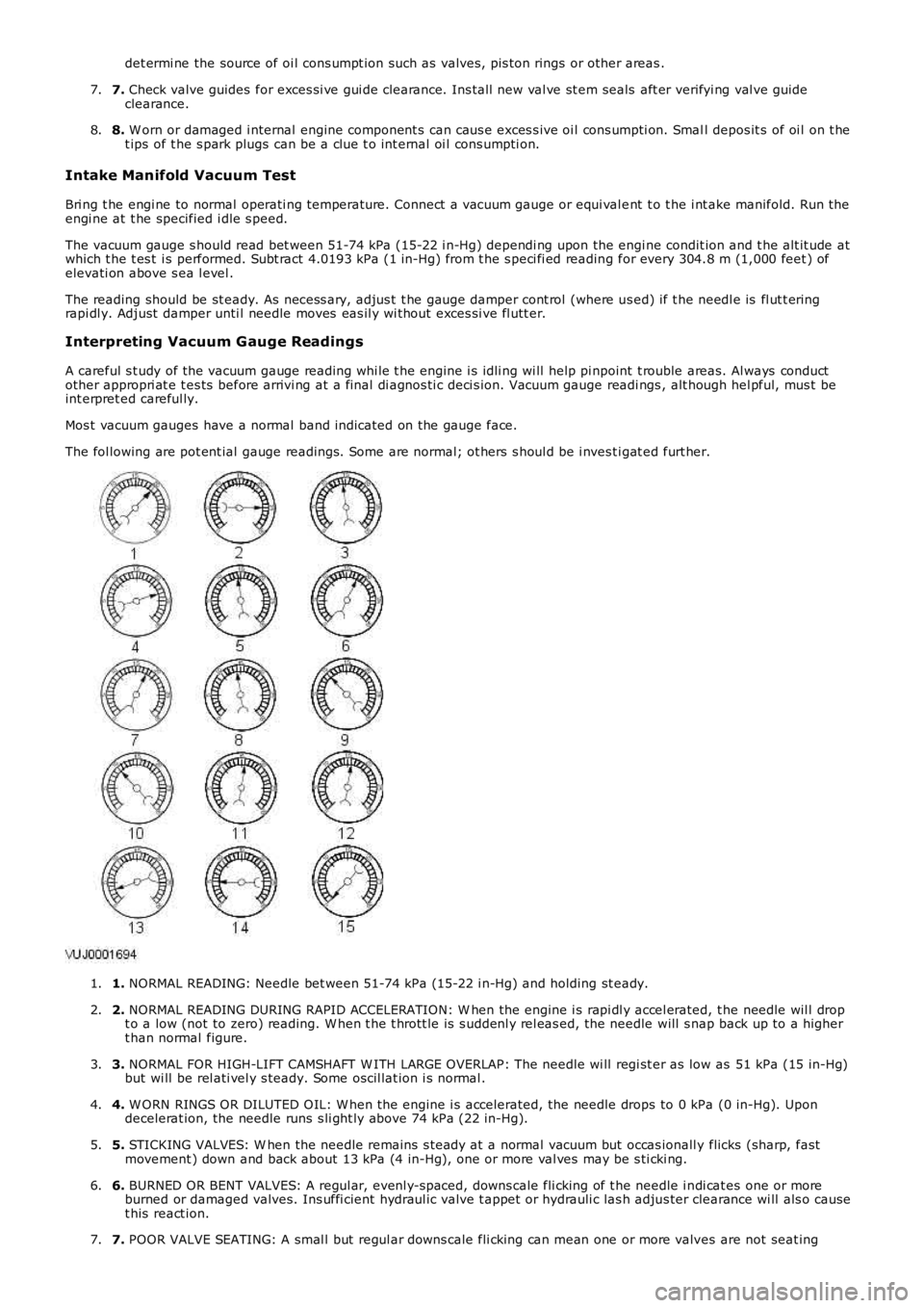
The fol lowing are pot ent ial gauge readings. Some are normal; ot hers s houl d be i nves ti gat ed furt her.
1. NORMAL READING: Needle bet ween 51-74 kPa (15-22 i n-Hg) and holding st eady.1.
2. NORMAL READING DURING RAPID ACCELERATION: W hen the engine i s rapi dl y accel erated, t he needle wil l dropt o a low (not to zero) reading. W hen t he t hrott le is s uddenl y rel eas ed, the needle will s nap back up to a highert han normal figure.
2.
3. NORMAL FOR HIGH-LIFT CAMSHAFT W ITH LARGE OVERLAP: The needle wi ll regi st er as low as 51 kPa (15 in-Hg)but wi ll be rel ati vel y s teady. Some oscil lat ion i s normal .3.
4. W ORN RINGS OR DILUTED OIL: W hen t he engine i s accelerated, the needle drops to 0 kPa (0 in-Hg). Upondecelerat ion, the needle runs s li ght ly above 74 kPa (22 in-Hg).4.
5. STICKING VALVES: W hen the needle remains s t eady at a normal vacuum but occas ionall y flicks (sharp, fastmovement ) down and back about 13 kPa (4 in-Hg), one or more val ves may be s ti cki ng.5.
6. BURNED OR BENT VALVES: A regul ar, evenl y-s paced, downs cale fli cking of t he needle i ndi cat es one or moreburned or damaged valves. Ins uffi cient hydraul ic valve t appet or hydrauli c las h adjus ter clearance wi ll als o causet his react ion.
6.
7. POOR VALVE SEATING: A smal l but regul ar downs cale fli cking can mean one or more valves are not seat ing7.
Page 752 of 3229
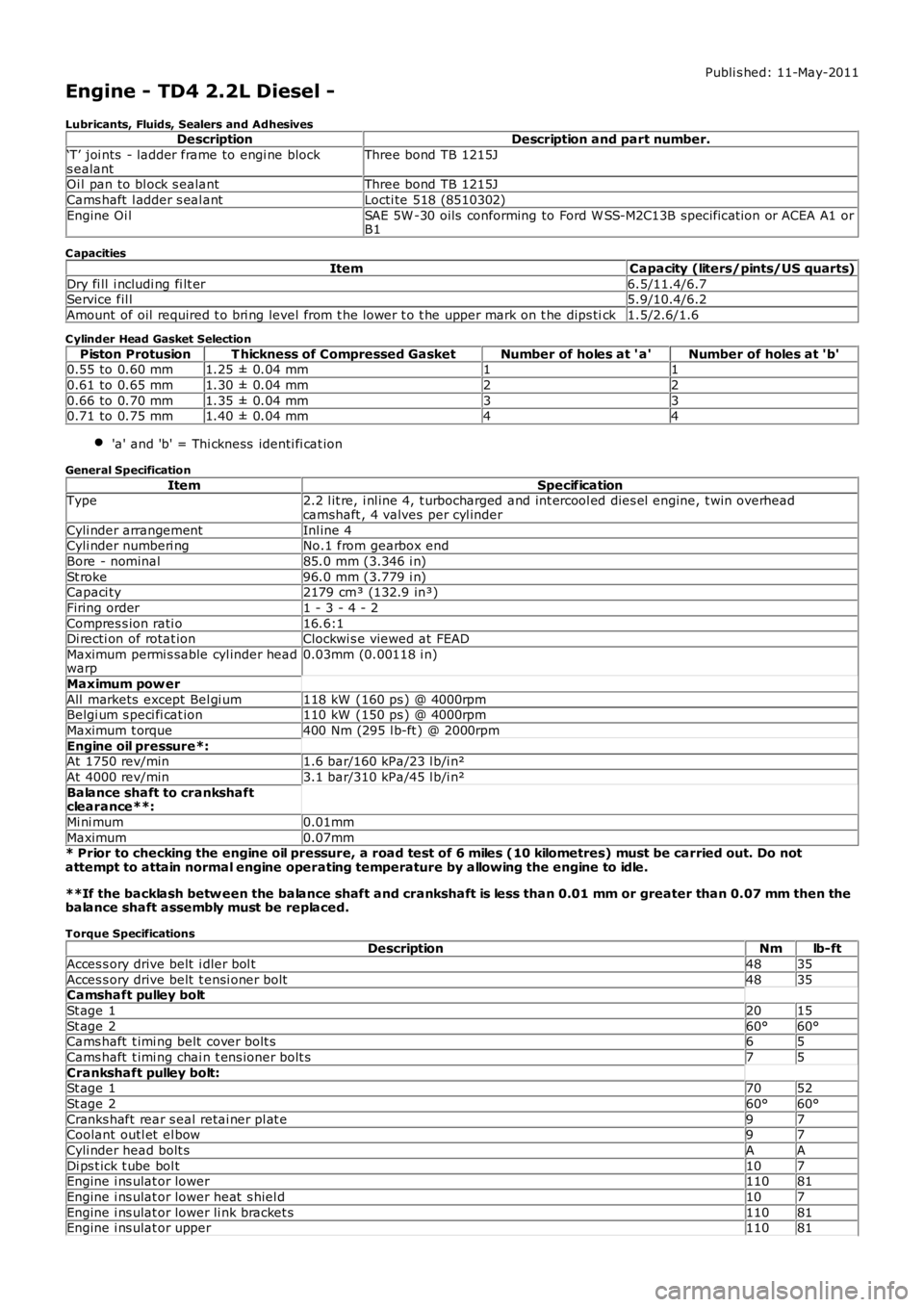
Publi s hed: 11-May-2011
Engine - TD4 2.2L Diesel -
Lubricants, Fluids, Sealers and AdhesivesDescriptionDescription and part number.
‘T’ joi nts - ladder frame to engi ne blocks ealantThree bond TB 1215J
Oi l pan to bl ock s ealantThree bond TB 1215J
Cams haft l adder s eal antLocti te 518 (8510302)
Engine Oi lSAE 5W -30 oils conforming to Ford W SS-M2C13B specificat ion or ACEA A1 orB1
C apacities
ItemCapacity (liters/pints/US quarts)
Dry fi ll i ncludi ng fi lt er6.5/11.4/6.7Service fil l5.9/10.4/6.2
Amount of oil required t o bri ng level from t he lower t o t he upper mark on t he dips tick1.5/2.6/1.6
C ylinder Head Gasket Selection
Piston ProtusionT hickness of Compressed GasketNumber of holes at ' a'Number of holes at 'b'0.55 to 0.60 mm1.25 ± 0.04 mm11
0.61 to 0.65 mm1.30 ± 0.04 mm22
0.66 to 0.70 mm1.35 ± 0.04 mm330.71 to 0.75 mm1.40 ± 0.04 mm44
'a' and 'b' = Thi ckness identi fi cat ion
General Specification
ItemSpecificationType2.2 l it re, i nl ine 4, t urbocharged and int ercool ed dies el engine, t win overheadcamshaft , 4 valves per cyl inder
Cyli nder arrangementInl ine 4Cyli nder numberi ngNo.1 from gearbox end
Bore - nominal85.0 mm (3.346 i n)
St roke96.0 mm (3.779 i n)Capaci ty2179 cm³ (132.9 in³)
Firing order1 - 3 - 4 - 2
Compres s ion rati o16.6:1Di recti on of rotat ionClockwi s e viewed at FEAD
Maximum permi s sable cyl inder headwarp0.03mm (0.00118 i n)
Maximum pow er
All markets except Bel gi um118 kW (160 ps ) @ 4000rpmBelgi um s peci fi cat ion110 kW (150 ps ) @ 4000rpm
Maximum t orque400 Nm (295 l b-ft ) @ 2000rpm
Engine oil pressure*:At 1750 rev/min1.6 bar/160 kPa/23 l b/i n²
At 4000 rev/min3.1 bar/310 kPa/45 l b/i n²
Balance shaft to crankshaftclearance**:
Mi ni mum0.01mm
Maximum0.07mm* Prior to checking the engine oil pressure, a road test of 6 miles (10 kilometres) must be carried out. Do notattempt to attain normal engine operating temperature by allowing the engine to idle.
**If the backlash betw een the balance shaft and crankshaft is less than 0.01 mm or greater than 0.07 mm then thebalance shaft assembly must be replaced.
Torque SpecificationsDescriptionNmlb-ft
Acces s ory drive belt i dler bol t4835
Acces s ory drive belt t ensi oner bolt4835Camshaft pulley bolt
St age 12015
St age 260°60°Cams haft t imi ng belt cover bolt s65
Cams haft t imi ng chai n t ens ioner bolt s75
Crankshaft pulley bolt:St age 17052
St age 260°60°
Cranks haft rear s eal retai ner pl at e97Coolant outl et el bow97
Cyli nder head bolt sAA
Di ps t ick t ube bol t107Engine i ns ulat or lower11081
Engine i ns ulat or lower heat s hiel d107
Engine i ns ulat or lower li nk bracket s11081Engine i ns ulat or upper11081
Page 775 of 3229
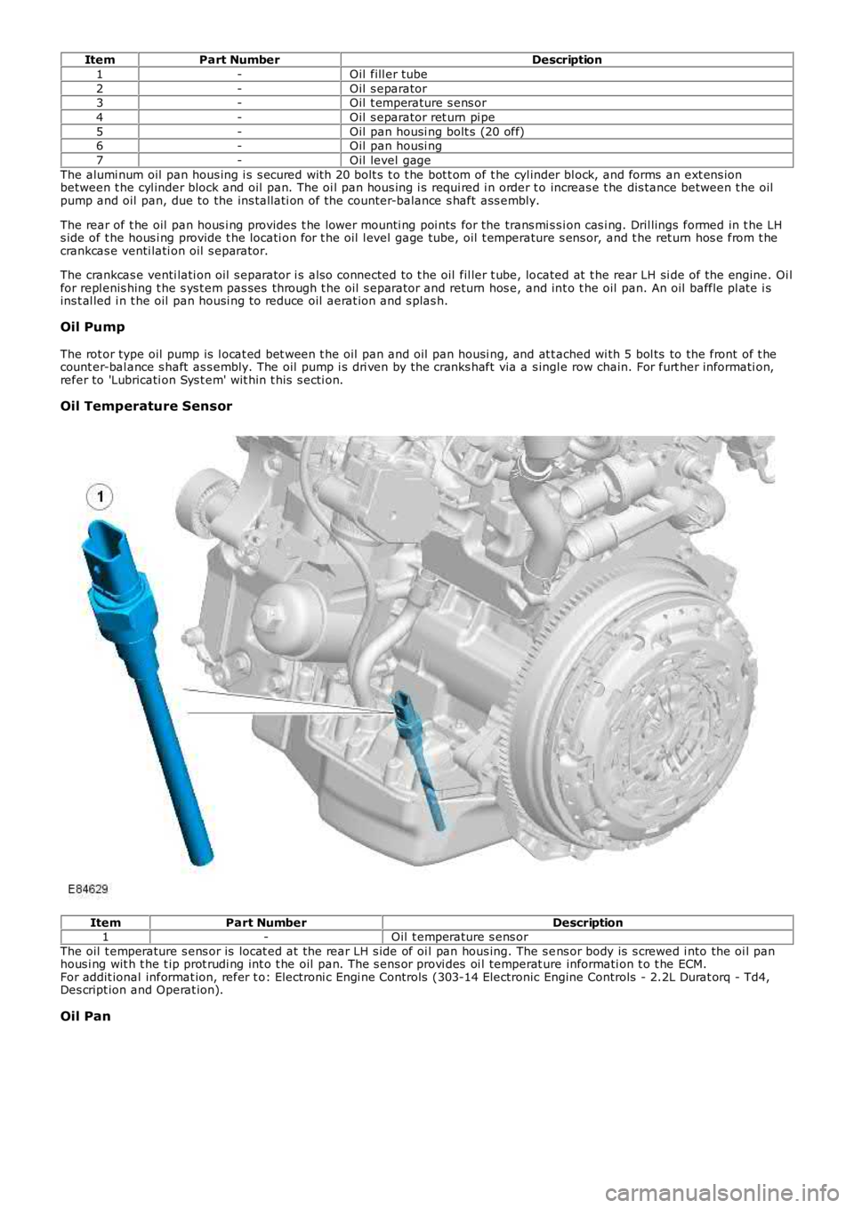
ItemPart NumberDescription
1-Oil fill er tube
2-Oil s eparator3-Oil t emperature s ens or
4-Oil s eparator ret urn pi pe
5-Oil pan housi ng bolt s (20 off)6-Oil pan housi ng
7-Oil level gage
The alumi num oil pan hous ing i s s ecured wit h 20 bolt s t o t he bot t om of t he cyl inder bl ock, and forms an ext ens ionbetween t he cyl inder block and oil pan. The oi l pan hous ing i s requi red i n order t o increas e t he dis tance between t he oilpump and oil pan, due to the ins tall ati on of the counter-balance s haft ass embly.
The rear of t he oil pan hous i ng provides t he lower mounti ng poi nts for the trans mi s si on cas i ng. Dril lings formed in t he LHs ide of t he hous i ng provide t he locati on for t he oil l evel gage tube, oil t emperature s ens or, and t he ret urn hos e from t hecrankcas e venti lati on oil s eparator.
The crankcas e venti lati on oil s eparator i s als o connected to t he oil fil ler t ube, located at t he rear LH si de of the engine. Oi lfor repl enis hing t he s ys t em pas ses through t he oil s eparator and return hos e, and int o t he oil pan. An oil baffle pl ate i sins t al led i n t he oil pan housi ng to reduce oil aerat ion and s plas h.
Oil Pump
The rot or type oil pump is l ocat ed bet ween t he oil pan and oil pan housi ng, and at t ached wi th 5 bol ts to the front of t hecount er-bal ance s haft as s embly. The oil pump i s dri ven by the cranks haft via a s ingle row chain. For furt her informati on,refer to 'Lubricati on Sys t em' wit hin t his s ecti on.
Oil Temperature Sensor
ItemPart NumberDescription1-Oil t emperature s ens or
The oil t emperature s ens or is locat ed at t he rear LH s ide of oi l pan hous ing. The s ens or body is s crewed i nto the oi l panhous i ng wit h t he t ip prot rudi ng int o t he oil pan. The s ens or provi des oi l temperat ure informati on t o t he ECM.For addit ional informat ion, refer t o: Electroni c Engi ne Controls (303-14 Electronic Engine Controls - 2.2L Durat orq - Td4,Des cript ion and Operat ion).
Oil Pan
Page 804 of 3229
1
2
3
4
5
6
7
8
9
10
11
12
1
2
3
1
2
3
4
5
6
7
8
9
• NOTE: W here pos si ble, compress i on tes t ing s houl d be carried out on an engine at normal operat ing temperat ure.
T ESTCONDIT IONSDET AILS/RESULT S/ACT IONS
A1: CARRY OUT A DRY CYLINDER COMPRESSION T EST
Make s ure t he parki ng brake is appl ied and t hat t he s elector l ever is in neutral (or park for vehi cl eswi th aut omati c transmis si on).
Set the ignit ion s t at us t o OFF.
Remove t he st art er rel ay.
Dis connect t he st art er motor s olenoid connect or.
Connect a s uit able remote st art er devi ce to the s t art er mot or s ol enoi d.
Remove t he glow pl ugs .REFER to: Gl ow Plugs (303-07B Glow Plug Sys tem, Removal and Ins tal lati on).
Ins t all s uit abl e adapt or in pl ace of t he glow plug i n t he fi rs t cyl inder to be tes t ed.
Connect a s uit able compres s ion t es ter t o the adapt or. See warni ng above.
Us ing t he remote s t art er device, crank t he engi ne a mi nimum of fi ve revoluti ons.
Record t he compres si on fi gure and t he number of revol uti ons taken to reach it .
Repeat s t eps 7 - 10 above for t he remai ning cylinders , cranking t he engine for a s imi lar number ofrevolut ions each ti me.
Compare the compres s ion figures acros s al l t he cylinders .
Are the compres s ion figures wit hi n 10% of each ot her?YesUnles s t he compres si on fi gures are uni vers al ly very low (experience wi ll indicat e thi s), check forother caus es for the cus tomer complaint .NoGO to A2.
A2: CARRY OUT A WET CYLINDER COMPRESSIO N T EST
CAUTION: If engi ne oil i s int roduced i nto the cyli nders, run t he engi ne at 2,000 rpm for a mi ni mum of t en mi nutesaft er compl eti ng tes t ing t o prevent damage to the catal yt ic convert ers . Fai lure to foll ow t his i nst ruct ion may res ul t indamage t o t he vehi cl e.
• NOTE: There is a combus ti on chamber i n the top of each pis ton. Make s ure that the oi l is not all owed t o run into thi schamber.Us ing a sui table oil can wit h a flexibl e s pout , int roduce a s mall amount of cl ean engi ne oil int o t hecyl inder jus t before tes t ing, such t hat the oi l i s able to run between t he pis t on and t he cyl inder bore.Repeat s t eps 7 - 10 from the tes t above, int roduci ng oil i nt o each cyl inder jus t before tes ti ng.
Compare the compres s ion figures acros s al l t he cylinders .
Is the compres s ion figure higher than t he dry tes t?YesA hi gher figure foll owing t he int roducti on of oi l may indi cat e a worn or damaged cyli nder bore, pi st onand/or pis t on ri ngs . Dis as s embl y would be required to confirm t his .NoIf the compres s ion figure is unaffect ed by t he int roducti on of oi l, but t he fi gure is s ti ll les s t han 90%of the ot her cyl inders , thi s may i ndi cat e a burnt and/or s t icking valve, leaking head gasket , et c.Dis as s embl y would be required to confirm t his .Clear any DTCs which may have been i nduced by t he tes t .
PINPOINT TEST B : OIL CONSUMPTION TEST
• NOTE: Oi l cons umpti on wil l vary, dependi ng on a number of fact ors . New engines will normall y us e more oil t han 'run-in'engines, once a cons umpt ion fi gure has been det ermined cont act Deal er Techni cal Support for furt her as s is t ance.T ESTCO NDIT IONSDET AILS/RESULT S/ACT IONS
B1: CHECK FOR EXCESSIVE OIL CONSUMPT IONStart the engine and al low it t o run unt il i t reaches normal operat ing temperat ure.
Make s ure t he vehi cl e i s parked on a l evel s urface and swi tch off.
All ow t o s et t le for at least five minutes .
Check t he oil l evel.
Correct t he level, i f necess ary, and record t he reading and mileage i n t he vehi cl e his t ory.
Make s ure t hat the owner/dri ver i s aware that a t est i s being carried out , and that t hey should nottop-up their oi l level for the durat ion of t he t est , but should check t he level every 160-240 Km(100-150 mil es ).
W hen t he oil l evel reaches the ADD mark, t he cust omer s houl d bri ng the vehicle in to be checked.
Top-up t he oil t o the level at t he beginning of t he tes t and record the amount of oil needed to dos o, and t he mi leage covered in the cours e of t he tes t .
From this , t he cons umpt ion can be calculated, and a decis ion made as to whet her or not t hecons umpti on is cons idered excess ive.Is the consumpt ion excess ive for the mil eage and/or us e? Contact Dealer Technical Support for furtherass is t ance.YesDis as sembl y wil l be required t o check t he components indicated i n t he s ympt om chart .NoNo furt her acti on is necess ary.
PINPOINT TEST C : CHECK THE ENGINE OIL PRESSU RE
• NOTE: The vehicle must be driven a minimum of 6 mil es (10 ki lometers ) prior t o t est ing t he oil press ure. Do not at temptt o att ain normal engi ne operati ng temperature by all owi ng t he engi ne to idle.
• NOTE: Check and, i f neces sary, t op-up t he engine oil l evel before begi nning t his test .
T EST CO NDIT IONSDET AILS/RESULT S/ACT IONSC1: CHECK FOR LOW ENGINE OIL PRESSURE
Page 946 of 3229
Entrained gases i n t he cool ing s ys tem escape t hrough the t hermal control modul e degas l ine t o t he cool ant res ervoir.
The increas ing coolant temperature is felt at t he t hermos tat , and is regi s tered on the ins trument cl us t er coolantt emperature gage vi a t he ECM and ECT s ens or s i gnal.For addit ional informat ion, refer t o: Ins t rument Clus ter (413-01 Inst rument Cl us t er, Des cript ion and Operat ion).
Engine Normal Operating Temperature
W i th the coolant t emperature increas ing, at 83°C (181°F) t he t hermos tat reacts and commences openi ng. The by-pas svalve is progres s ively clos ed. Hot coolant ret urning from t he engi ne t o t he thermal control modul e i s now all owed to pas st hrough the t op hos e connecti on to the radiator. The fl ow of hot coolant t o t he radiat or now forces cold cool ant wi thi n t heradi at or and bot t om hos e t o fl ow t o t he thermal cont rol module.
Duri ng the thermos t at opening period t here i s an i nit ial temperat ure di fferenti al of t he coolant at bot h s ides of t het hermos tat . The thermos t at react s t o t he t emperature different ial and part iall y closes , whi le t he by-pas s val ve opensfurther. The thermos t at and by-pas s valve conti nue to oscil lat e whil e t he cool ant t emperat ure i ncreas es .
At a coolant temperat ure of 91°C (196°F) t he thermost at is full y opened and t he by-pas s valve i s ful ly clos ed. The returncool ant from t he engi ne is now ful ly circul ated t hrough t he radiat or and bot tom hose. Coolant flows t hrough the radiat orfrom the RH tank t o t he LH t ank, and i s cool ed by air pass i ng through the mat ri x. Ent rai ned gas es i n the radiat or es capet hrough the connect ed degas l ine t o t he cool ant res ervoir.
The increas ed cool ant volume created by heat expans ion caus es the coolant level to ri se through t he connecti ng res ervoirhose, and i nt o t he res ervoi r.
The t emperature of the cooli ng s ys t em i s cons t ant ly moni tored by t he ECM via the ECT s ens or s i gnal. The ECM uses t heECT s ignal to control operati on of the cooling fans , and to adjus t engine fueling. The ECM al so operates t he fans i nres ponse to input s from the aut omati c t ransmis s ion oil t emperat ure s ensor, Air Condit ioning (A/C) s ys tem cont rol s wit ch,and t he A/C pres sure s ens or. For addit ional i nformati on, refer to: El ect ronic Engine Cont rols - 2.2L Di es el (303-14Electroni c Engine Controls - 2.2L Dies el, Des cript ion and Operat ion).For addit ional informat ion, refer t o: Air Condit ioning (412-01 Cli mat e Cont rol , Descripti on and Operat ion).
The cool ing fan s peed is als o infl uenced by vehicle road s peed. The ECM adjus t s the speed of t he cool ing fans tocompens ate for t he ram air effect , us ing t he CAN bus road speed s ignal received from the Ant i-Lock Brake Sys tem (ABS)module.
W hen t he engine i s s hut down, t he coolant t emperature and volume decreas e. The thermos t at st art s t o clos e as t hecool ant t emperat ure decreas es to 89°C (192°F), and is fully cl osed at 81°C (178°F). The coolant level wit hin t he res ervoi rdecreas es as coolant is drawn from the res ervoi r to replenis h the s ys tem.
Followi ng engi ne s hut down when the coolant pump i s s tat ionary, the ECM may cont inue t o operat e t he cool ing fans for apre-det ermined peri od to maint ai n engine cooling.
Page 1133 of 3229
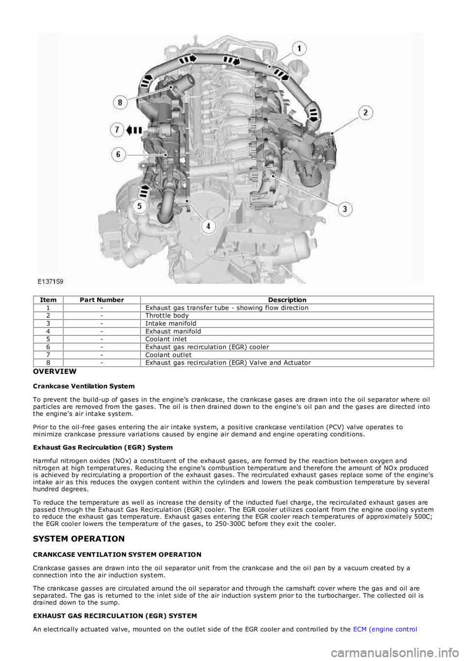
ItemPart NumberDescription
1-Exhaus t gas t rans fer t ube - showi ng fl ow direct ion2-Throt t le body
3-Intake mani fold
4-Exhaus t mani fold5-Coolant i nl et
6-Exhaus t gas reci rculati on (EGR) cooler
7-Coolant outl et8-Exhaus t gas reci rculati on (EGR) Val ve and Act uator
OVERVIEW
Crankcase Ventilation System
To prevent the bui ld-up of gas es in the engine's crankcase, t he crankcas e gas es are drawn int o t he oil s eparator where oi lpart icles are removed from the gas es . The oi l is t hen drai ned down to the engine's oi l pan and the gas es are di rected intot he engi ne's air i nt ake s ys t em.
Pri or to t he oil -free gas es entering t he air i ntake s yst em, a pos it ive crankcas e venti lat ion (PCV) val ve operat es t omi ni mi ze crankcase pres sure vari at ions caused by engi ne air demand and engi ne operati ng condi ti ons .
Exhaust Gas R ecirculation (EGR) System
Harmful nit rogen oxides (NO x) a cons ti tuent of the exhaust gas es, are formed by t he react ion between oxygen andnit rogen at high t emperat ures . Reducing t he engine's combust ion temperat ure and t herefore t he amount of NO x producedis achieved by reci rculati ng a proporti on of the exhaust gas es. The reci rculat ed exhaus t gas es repl ace some of the engine'sint ake air as t hi s reduces the oxygen cont ent wit hin t he cyl inders and lowers t he peak combus t ion t emperat ure by s everalhundred degrees.
To reduce t he temperature as well as i ncreas e t he densi ty of t he i nducted fuel charge, t he recircul ated exhaus t gas es arepass ed t hrough t he Exhaus t Gas Reci rculati on (EGR) cooler. The EGR cool er ut il izes cool ant from t he engi ne cool ing s yst emt o reduce the exhaust gas t emperat ure. Exhaus t gas es ent ering t he EGR cooler reach temperatures of approxi matel y 500C;t he EGR cool er lowers t he t emperature of t he gas es , to 250-300C before t hey exit t he cool er.
SYSTEM OPERATION
CRANKCASE VENT ILAT ION SYST EM OPERAT IO N
Crankcas e gas s es are drawn int o t he oil s eparator unit from the crankcase and the oil pan by a vacuum creat ed by aconnecti on int o t he air inducti on sys t em.
The crankcas e gas ses are circul at ed around t he oil s eparator and t hrough t he cams haft cover where t he gas and oil ares eparated. The gas is returned to the i nlet s ide of t he air inducti on s ys t em prior to the t urbocharger. The collected oi l isdrai ned down to the s ump.
EXHAUST GAS RECIR CULAT ION (EGR) SYST EM
An elect ricall y actuated val ve, mounted on the out let s ide of t he EGR cooler and cont rol led by t he ECM (engi ne cont rol