2006 LAND ROVER FRELANDER 2 high beam
[x] Cancel search: high beamPage 42 of 3229
commencement of work.
Dis pos abl e heavy dut y plas ti c gloves s houl d be worn at all ti mes , and the affected area was hed down usi ng wire wool anda l imewat er (calcium hydroxi de) s olut ion t o neutrali se the acid before di spos ing of t he decompos ed Vit on res i due and fi nalcleaning of t he area. Aft er us e, t he plas ti c gloves should be dis carded carefull y and s afely.
Welding
W el di ng process es i ncl ude Res i st ance W elding (Spot W eldi ng), Arc W elding and Gas W eldi ng.
Resistance Welding
This proces s may cause parti cles of molt en met al to be emit ted at a high velocit y, and t he eyes and s ki n mus t beprot ect ed.
Arc Weld ing
This proces s emit s a hi gh level of ul tra-vi ol et radiat ion whi ch may caus e arc-eye and s ki n burns t o t he operator and t oother pers ons nearby. Gas -shi el ded welding proces s es are parti cul arly hazardous i n thi s res pect . Pers onal prot ecti on mus tbe worn, and s creens us ed to shi eld ot her people.
CONTACT LENS W EARERS ARE ADVISED TO REVERT TO ORDINARY SPECTACLES W HEN ARC W ELDING as t he arc spectrumis bel ieved to emit microwaves which dry out t he fluid bet ween t he lens and t he eye. This may res ult i n bli ndnes s whent he lens is removed from the eye.
Metal s patt er wil l al so occur, and appropri ate eye and skin prot ect ion i s neces s ary.
The heat of t he weldi ng arc wi ll produce fumes and gas es from the metals bei ng welded, the rods and from any appli edcoat ings or cont aminat ion on t he s urfaces being worked on. Thes e gas es and fumes may be toxic and inhalati on of thes es houl d be avoided. The us e of extract ion vent ilat ion t o remove the fumes from the working area may be neces s arypart icularl y in cas es where the general vent il ati on is poor, or where cons iderabl e weldi ng work i s anti ci pated. In ext remecas es or confined s paces where adequat e vent il ati on cannot be provided, air-fed res pirators may be neces s ary.
CAUTION: Some of t he components ins tal led t o t he vehi cl e e.g. t he int eri or cros s beam and underbonnet crossmember are manufact ured from magnesi um al loy. On no account s houl d any welding operat ions be at t empt ed on t hesecomponents .
Gas Welding (and Cutting)
Oxy-acet ylene t orches may be us ed for wel di ng and cutt ing, and s pecial care mus t be t aken to prevent l eakage of t hes egases , wit h consequent ri sk of fire and explos ion.
The process wil l produce met al spat ter and eye and s kin prot ecti on is necess ary.
The fl ame i s bri ght , and eye prot ect ion s hould be us ed, but t he ult ra-violet emi s si on is much les s than t hat from arcweldi ng, and l ighter filt ers may be us ed.
The process it sel f produces few t oxi c fumes , but s uch fumes and gases may be produced from coati ngs on the work,part icularl y duri ng cut ti ng away of damaged body parts , and inhalat ion of t he fumes s hould be avoided.
In brazing, toxic fumes may be produced from t he metal s in the brazi ng rod, and a s evere hazard may ari se if brazing rodscont aining cadmi um are used. In t hi s event parti cular care must be taken t o avoi d i nhalat ion of fumes and expert advi cemay be requi red.
SPECIAL PRECAUT IO NS MUST BE T AKEN BEFORE ANY WELDING OR CUT T ING T AKES PLACE ON VESSELS WHICHHAVE CO NT AINED COMBUST IBLE MAT ERIALS, FO R EXAMPLE BO ILING O R ST EAMING O UT OF FUEL T ANKS.
Warning Symbols on Vehicles
Decal s s howi ng warni ng s ymbol s wil l be found on various vehi cl e component s.
Thes e decals mus t not be removed. The warni ngs are for the at tent ion of owners /operat ors and persons carrying outs ervice or repair operat ions on t he vehicle.
Page 585 of 3229

Publi s hed: 11-May-2011
Steering Column Switches - Steering Column Switches
Des cript ion and Operat ion
COMPONENT LOCATION
ItemPart NumberDescription
1-Speed cont rol s wit ches2-St eering column cas e containi ng the mult ifunct ion s wit ches and cl ocks pring
3-Audio control swit ches
OVERVIEW
The winds hield wiper s wit ch is l ocat ed in the right -hand-s ide of t he cas e and retai ned wit h 2 s crews . The s wit ch isconnected t o t he mai n harness vi a a connect or at the back of the s wi tch. The s wit ch cont rols the followi ng functi ons :
W i nds hiel d wi per i nt ermit tent s low and fas t speedW i nds hiel d wi per fli ck wipeW i nds hiel d was h/wi peRear was h/wipeInt ermit tent delay s electi on.
The t urn s ignal indicator s wit ch is locat ed i n t he left -hand-si de of the cas e and ret ained wi th 2 s crews . The swi tch i sconnected t o t he mai n harness vi a a connect or on the back of t he swit ch. The s wit ch cont rol s the foll owing funct ions:
Left / right turn s ignal operati onHigh / low beam operati onHeadl amp flas hTri p comput er functi on s el ect ion (i f fit t ed).
The t rip but t on allows the driver to cycle t hough an opti on menu and als o reset t ri p cycl e mi leage cal cul ati ons . The t ripcomput er informat ion i s dis played in the i nst rument clus ter mes s age cent er (high line ins trument cl us t er onl y).
Steering wheel mount ed s wit ches on the right -hand-s ide of t he dri ver's ai rbag, cont rol the audi o and tel ephone funct ions.Swit ches on the l eft -hand-s ide of t he dri ver's ai rbag control t he s peed cont rol functi ons .
The clocks pri ng is locat ed i n the front of t he cas e and retai ned wit h four s crews . The clocks pri ng engages i n s lots in t hes teeri ng wheel bos s and t urns wi th the rotat ion of t he s teeri ng wheel. The clocks pring incorporat es a t ang which cancelst he turn s ignal indicators when the st eering wheel i s rot ated.For addit ional informat ion, refer t o: Air Bag and Safet y Belt Pretens ioner Supplement al Res traint Syst em (SRS) (501-20BSuppl ement al Rest rai nt Sys tem, Des cri pti on and Operati on).
CONTROL DIAGRAM
• NOTE: A = Hardwi red; D = Hi gh s peed CAN bus , O = LIN bus
Page 587 of 3229
11-Int egrated audio modul e
12-Int egrated control modul e
PRINCIPLES OF OPERATION
Windshield Wiper Switch
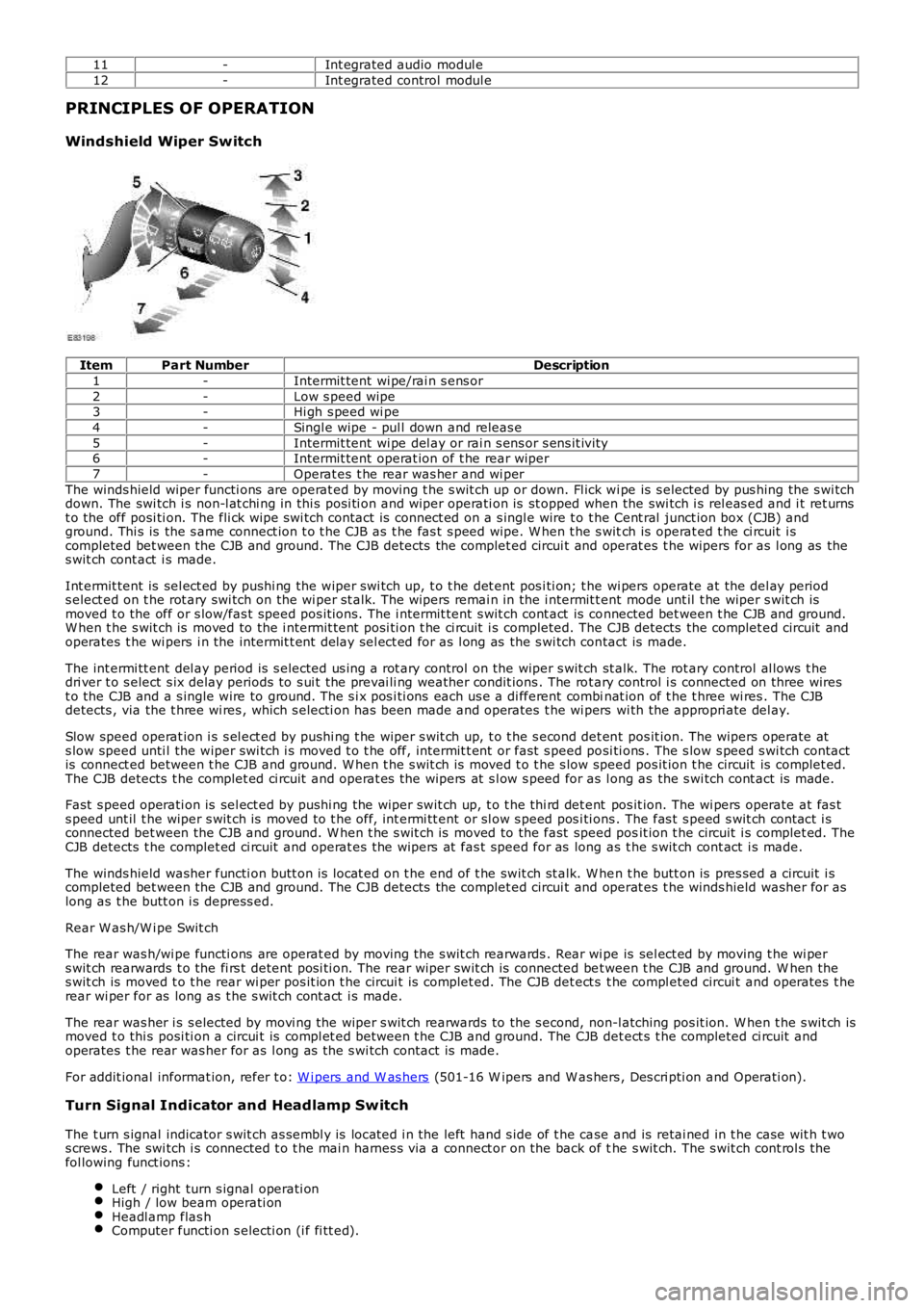
ItemPart NumberDescription
1-Intermit tent wi pe/rai n s ens or
2-Low s peed wipe3-Hi gh s peed wi pe
4-Singl e wipe - pul l down and releas e
5-Intermit tent wi pe del ay or rai n s ens or s ens it ivi ty6-Intermit tent operat ion of t he rear wiper
7-Operat es t he rear was her and wi per
The winds hield wiper functi ons are operat ed by moving t he s wit ch up or down. Fl ick wi pe is s elected by pus hing the s wi tchdown. The swi tch i s non-l at chi ng in thi s posi ti on and wiper operati on is st opped when the swi tch i s rel eas ed and i t ret urnst o the off posi ti on. The fli ck wipe s wi tch contact is connect ed on a s ingl e wire t o t he Cent ral junct ion box (CJB) andground. Thi s is the s ame connect ion t o t he CJB as t he fas t s peed wipe. W hen t he s witch is operat ed t he ci rcuit i scompleted bet ween the CJB and ground. The CJB detects the complet ed circui t and operat es t he wipers for as l ong as thes wit ch cont act i s made.
Int ermit tent is sel ect ed by pushi ng the wiper swi tch up, t o t he det ent pos i ti on; t he wi pers operate at the del ay periods elect ed on t he rot ary swi tch on the wi per st alk. The wipers remai n in the i ntermit tent mode unt il t he wiper s wit ch ismoved t o the off or s low/fas t speed pos it ions. The i ntermit tent s wit ch cont act is connected bet ween t he CJB and ground.W hen t he s wit ch is moved to the i ntermit tent posi ti on t he ci rcuit i s completed. The CJB detects the complet ed circuit andoperates t he wi pers i n the intermit t ent delay sel ect ed for as l ong as the s wi tch contact is made.
The int ermi tt ent del ay period is s elected us i ng a rot ary control on the wiper s wit ch st alk. The rot ary control al lows t hedri ver t o s elect s ix delay periods to s ui t the prevai li ng weather condit ions . The rot ary control i s connected on three wirest o the CJB and a s ingle wire to ground. The s i x pos i ti ons each us e a di fferent combinat ion of t he t hree wi res . The CJBdetects , via the t hree wi res , which s electi on has been made and operates t he wi pers wi th the appropri ate del ay.
Slow speed operat ion i s s el ect ed by pus hi ng t he wiper s wit ch up, t o t he s econd det ent pos it ion. The wipers operate ats low speed unti l the wiper swi tch i s moved t o t he off, intermit t ent or fast s peed posi ti ons . The s low s peed s wi tch contactis connect ed between t he CJB and ground. W hen t he s wit ch is moved t o t he s low speed pos it ion t he circuit is complet ed.The CJB detects t he complet ed ci rcuit and operat es the wipers at s l ow s peed for as long as the s wi tch cont act is made.
Fast s peed operati on is sel ect ed by pushi ng the wiper swit ch up, t o t he thi rd det ent pos it ion. The wi pers operate at fas ts peed unt il t he wiper s wit ch is moved to t he off, int ermi tt ent or sl ow s peed pos i ti ons . The fas t s peed s wit ch cont act i sconnected bet ween the CJB and ground. W hen t he s wit ch is moved to the fast speed posit ion t he circuit i s complet ed. TheCJB detects t he complet ed ci rcuit and operat es the wipers at fas t speed for as long as t he s wit ch cont act i s made.
The winds hield washer functi on butt on is locat ed on t he end of t he swit ch st alk. W hen t he butt on is pres sed a circuit i scompleted bet ween the CJB and ground. The CJB detects the complet ed circui t and operat es t he winds hield washer for aslong as t he butt on i s depress ed.
Rear W as h/W i pe Swit ch
The rear was h/wi pe functi ons are operat ed by moving t he s wit ch rearwards . Rear wi pe is sel ect ed by moving t he wi pers wit ch rearwards t o the fi rs t detent posi ti on. The rear wiper swit ch is connected bet ween t he CJB and ground. W hen thes wit ch is moved t o t he rear wi per pos it ion t he circui t is complet ed. The CJB det ect s t he compl eted circui t and operates t herear wi per for as long as t he s wit ch cont act i s made.
The rear was her i s s elected by movi ng the wiper s wit ch rearwards to the s econd, non-l atching pos it ion. W hen t he s wit ch ismoved t o thi s posi ti on a circui t is compl et ed between t he CJB and ground. The CJB det ect s t he completed ci rcuit andoperates t he rear was her for as l ong as the s wi tch contact is made.
For addit ional informat ion, refer t o: W i pers and W as hers (501-16 W ipers and W as hers , Des cri pti on and Operati on).
Turn Signal Indicator and Headlamp Switch
The t urn s ignal indicator s wit ch as sembl y is locat ed i n the left hand s ide of t he case and is retai ned in t he case wit h t wos crews . The swi tch i s connected t o t he mai n harnes s via a connect or on the back of the s wit ch. The s wit ch cont rol s thefol lowing funct ions :
Left / right turn s ignal operati onHigh / low beam operati onHeadl amp flas hComputer functi on s electi on (i f fi tt ed).
Page 588 of 3229
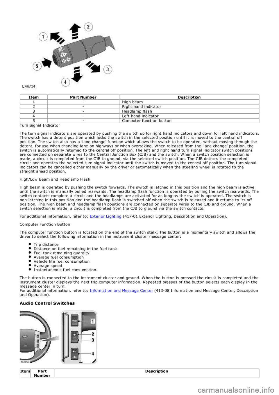
ItemPart NumberDescription
1-High beam2-Ri ght hand i ndicat or
3-Headlamp fl ash
4-Left hand indicator5-Comput er funct ion but ton
Turn Si gnal Indi cat or
The t urn s ignal indicators are operat ed by pus hing t he s wit ch up for right hand indicators and down for l eft hand indicat ors .The s wit ch has a detent posi ti on which l ocks t he s wit ch in the s elected pos it ion until i t is moved t o t he cent ral offposi ti on. The s wi tch al so has a 'l ane change' funct ion whi ch al lows t he s wit ch t o be operat ed, wi thout moving t hrough t hedetent, for use when changing l ane on highways or when overtaking. W hen released from t he 'l ane change' pos it ion, thes wit ch is aut omati cal ly returned t o t he cent ral off pos it ion. The l eft and ri ght hand t urn si gnal i ndi cat or swit ch pos it ionsare connect ed on s eparate wires to the Cent ral Juncti on Box (CJB) and t he s wit ch. W hen a s wit ch pos i ti on sel ect ion i smade, a circui t is complet ed from t he CJB t o ground, vi a t he s elect ed s wit ch posi ti on. The CJB det ect s t he compl etedcircuit and operat es t he s el ect ed t urn s ignal indicator unt il the swi tch i s moved t o t he cent ral off pos it ion. The turn s ignalindicat ors can be cancell ed eit her manuall y by t he dri ver or automat icall y when t he st eeri ng wheel i s rot ated t o t hes traight ahead pos it ion.
High/Low Beam and Headlamp Fl as h
High beam is operat ed by pus hi ng t he swit ch forwards. The s wi tch i s lat ched i n t his pos it ion and t he high beam is acti veunti l the s wi tch i s manual ly pul led rearwards . The headl amp fl ash functi on is operated by pull ing t he s wit ch rearwards. Thes wit ch cont act s complete a circui t and the headlamps are acti vat ed for as l ong as the swi tch i s operated. The s wit ch isnon-lat chi ng in thi s pos i ti on and the headlamp fl as h is s wit ched off when t he s wit ch is releas ed and it returns to i ts offposi ti on. The hi gh beam and headl amp flas h pos it ions are connect ed on s eparate wires to the CJB and ground. W hen as wit ch s el ect ion i s made, a circui t is complet ed from the CJB t o ground vi a the swi tch contacts .
For addit ional informat ion, refer t o: Ext eri or Li ght ing (417-01 Ext erior Light ing, Descri pti on and Operat ion).
Computer Funct ion But ton
The comput er functi on but t on is l ocat ed on t he end of the s wi tch s t al k. The but ton is a momentary s wit ch and al lows t hedri ver t o s elect the foll owing i nformat ion in t he ins t rument clus ter mes s age cent er:
Tri p dis t anceDis t ance on fuel remaini ng in the fuel t ankFuel t ank remai ni ng quant it yAverage fuel cons umpt ionVehicle l ife fuel cons umpt ionAverage s peedIns t ant aneous fuel cons umpt ion.
The butt on is connect ed t o t he ins trument cl ust er and ground. W hen the but ton is pres s ed t he ci rcuit i s completed and theins t rument clus ter dis plays t he next t ri p computer informat ion. Repeat ed pres ses of t he butt on s elects each dis play i n t hemes s age center i n t urn.For addit ional informat ion, refer t o: Informat ion and Mes s age Cent er (413-08 Informat ion and Mes s age Cent er, Des cript ionand Operat ion).
Audio Control Switches
ItemPartNumberDescription
Page 773 of 3229
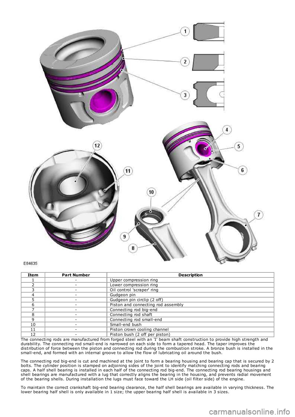
ItemPart NumberDescription
1-Upper compres si on ri ng2-Lower compres si on ri ng
3-O il cont rol 's craper' ring
4-Gudgeon pin5-Gudgeon pin ci rcli p (2 off)
6-Pi st on and connecti ng rod ass embly
7-Connect ing rod big-end8-Connect ing rod s haft
9-Connect ing rod s mall -end
10-Smal l-end bus h11-Pi st on crown cooli ng channel
12-Pi st on bus h (2 off per pis ton)
The connecti ng rods are manufactured from forged s teel wi th an 'I' beam shaft cons truct ion t o provi de high s t rength anddurabil it y. The connect ing rod s mall -end i s narrowed on each s i de to form a tapered head. The taper improves t hedis t ribut ion of force between t he pis t on and connect ing rod duri ng t he combus t ion s troke. A bronze bush is i nst all ed in t hes mall -end, and formed wit h an internal groove t o al low t he flow of l ubricati ng oil around t he bush.
The connecti ng rod bi g-end i s cut and machined at t he joi nt to form a bearing housi ng and bearing cap t hat is s ecured by 2bolt s. The cyli nder pos it ion i s s tamped on adjoi ning s ides of t he joi nt to i dent ify mat chi ng connecti ng rods and beari ngcaps . A hal f shell beari ng is ins tall ed in each half of t he connecti ng rod bi g-end. The connect ing rod beari ng hous ings ands hel l bearings are manufact ured wit h a l ug that correct ly al igns t he bearing i n t he hous i ng, and prevents radial movementof the bearing s hells . Duri ng ins t al lat ion t he lugs mus t face toward the LH s ide (oil fi lt er si de) of t he engine.
To mai nt ain the correct cranks haft big-end bearing clearance, the hal f shell beari ngs are avail abl e in varying t hicknes s . Thelower beari ng hal f s hel l is only avail abl e i n 1 s ize; t he upper beari ng hal f s hel l is avail abl e in 3 s izes .
Page 1769 of 3229
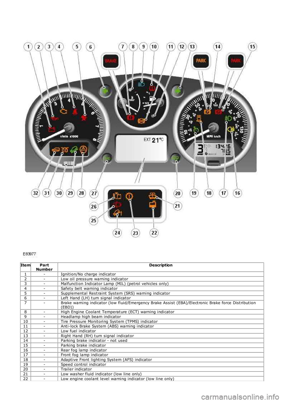
ItemPartNumberDescription
1-Ignit ion/No charge indicat or
2-Low oil pres s ure warning i ndi cat or3-Malfuncti on Indi cat or Lamp (MIL) (pet rol vehi cl es only)
4-Safety bel t warning indicator
5-Supplement al Res t raint Sys tem (SRS) warni ng indicator6-Left Hand (LH) t urn si gnal i ndi cat or
7-Brake warni ng indicator (low fl ui d/Emergency Brake As s is t (EBA)/El ect ronic Brake force Dis t ribut ion(EBD))8-High Engine Coolant Temperat ure (ECT) warning i ndi cat or
9-Headl amp high beam indicator
10-Tire Pres sure Monit ori ng Sys t em (TPMS) indicator11-Ant i-lock Brake Sys tem (ABS) warning i ndi cat or
12-Low fuel indicat or
13-Right Hand (RH) t urn si gnal i ndi cat or14-Parking brake i ndicat or - not used
15-Parking brake i ndicat or
16-Rear fog lamp indicator17-Front fog l amp i ndi cat or
18-Adapt ive Front l ighti ng Sys t em (AFS) indicator
19-Speed control indicator20-Trail er indicator
21-Low was her fluid indicator (low line onl y)
22-Low engi ne cool ant l evel warni ng indi cat or (low li ne only)
Page 1771 of 3229
Vehicle i n power mode 6 (all vehi cles except NAS vehicles )Vehicle i n power mode 6 for 75 s econds (NAS vehicl es onl y)Vehicle s peed is greater t han 6 mph (10 kph)Dri vers s afet y belt not s ecured in i ts buckleLarge pas senger det ect ed i n front pas s enger s eat wit h an uns ecured safety bel t.
The warni ng indicator wi ll flas h at a frequency of 2 Hz while accompani ed by a chime from the i nst rument clus ter for 10s econds. Thi s is foll owed by a 10 s econd period where the warning i ndicat or is permanent ly ill uminat ed and the s ounder i ss il ent . Thi s 10 s econd cycle wi ll be repeat ed for a maxi mum of 190 seconds or any of t he condit ions l is t ed above cease toexis t.
Supplemental Restraint System Warning Indicator
The Suppl ement al Rest rai nt Sys tem (SRS) warning i ndi cat or is i lluminated on recei pt of a medium s peed CAN bus si gnalfrom the CJB. The si gnal originat es in t he RCM whi ch monit ors t he condi ti on of the SRS and ill uminat es the red warni ngindicat or accordingly.
The SRS warni ng indicator i s il lumi nat ed by t he RCM for a 6 s econd bul b check when the vehicle firs t ent ers power mode 6.If a fault is detect ed wit h t he indicator, the ins trument cl us t er returns a medi um speed CAN bus s ignal vi a t he CJB to theRCM and a Diagnos t ic Troubl e Code (DTC) i s s tored in the RCM's memory. The mes s age 'SrS' wi ll als o be di spl ayed i n t heodometer.For addit ional informat ion, refer t o: Informat ion and Mes s age Cent er (413-08 Informat ion and Mes s age Cent er, Des cript ionand Operat ion).
Left and Right Hand Turn Signal Indicators
The green l eft and right hand turn s ignal i ndicat ors are i ll uminated on recei pt of medium speed CAN bus s i gnals from t heCJB. The CJB provi des a CAN bus s ignal wit h one of t he foll owing values :
0 - LH st eeri ng col umn mul ti -funct ion s wit ch in the central pos it ion1 - LH st eeri ng col umn mul ti -funct ion s wit ch in the LH turn posi ti on2 - LH st eeri ng col umn mul ti -funct ion s wit ch in the RH turn pos it ion3 - Hazard fl as hers reques t ed.
If the vehicle is i n power mode 6 t he ins trument cl ust er wil l fl as h the appropri ate turn s ignal i ndicat or if a medium speedCAN bus s ignal is recei ved wit h a value of 1 or 2. Medi um s peed CAN bus s ignals wi th a value of 3 wi ll acti vat e both theLH and RH turn s ignal i ndicat ors si mult aneous ly i rrespecti ve of power mode.
W hen acti vat ed, the l eft and right hand turn s ignal indicators wil l be accompanied by 'ti ck t ock' chimes from t he ins trumentclus ter s ounder.
Brake Warning Indicator
EBA and EBD warnings are trans mi tt ed t o t he CJB from t he ABS module over t he high s peed CAN bus . Thes e s ignals arerel ayed t o t he i ns t rument clus ter on t he medium s peed CAN bus and wil l act ivate the brake warning i ndicat or when t hevehi cl e i s in power mode 6. If an EBA warni ng is request ed, the i ndi cat or wil l ill uminat e in an amber color. If an EBDwarni ng is reques t ed, t he indi cat or will i ll uminate in a red color.
Low brake flui d level warnings are als o t rans mit t ed to the i nst rument clus t er from the CJB on the medi um s peed CAN bus .The s ignal origi nat es in the ABS modul e which recei ves a hardwired input from the brake flui d level s ens or. If a l ow brakefl uid warning i s reques ted, the indicator wil l il lumi nat e i n a red col or when the vehicle is i n power mode 6.
The brake warni ng indi cat or i s als o s ubject t o a 3 second bul b check when the vehicle firs t ent ers power mode 6. Theindicat or wi ll i lluminate in a amber color for 1.5 s econds t hen a red col or for 1.5 s econds .
High Eng ine Coolant Temperature Warning Ind icator
The red hi gh Engine Coolant Temperature (ECT) warning i ndi cat or is control led by the engine t emperat ure gage s oft ware(see above).
Headlamp High Beam Indicator
The blue headlamp hi gh beam i ndi cat or is i ll uminated on recei pt of a medium s peed CAN bus si gnal from the CJB. Thes ignal origi nat es in the l ight s wit ch module and i s t ransmit ted t o t he CJB over t he LIN bus. The i nst rument clus t er will onlyil lumi nat e t he headl amp high beam indicator when t he vehicle i s in power mode 6 and t he LH s teeri ng column mul ti -functi on s wit ch is moved t o t he high beam pos i ti on.
Tire Pressure Monitoring System Indicator
The Tire Pres s ure Moni tori ng Syst em (TPMS) indicator i s cont rol led by t he ins t rument clus ter on receipt of medium s peedCAN bus s ignals from t he CJB. The s ignal ori gi nates i n t he TPMS module. The indicator i s il lumi nat ed in an amber col or fora 3 second bulb check by the TPMS modul e when t he vehi cl e enters power mode 6. If t he indicator remains i lluminated orfl ashes after t he engi ne is st art ed or when dri vi ng, the TPMS has developed a faul t. The t ire pres s ures s houl d bemonit ored manuall y unti l the fault is recti fi ed.For addit ional informat ion, refer t o: W heels and Ti res (204-04 W heels and Tires , Des cript ion and Operat ion).
Anti-lock Brake System Warning Indicator
The Anti -l ock Brake Sys t em (ABS) warning i ndicat or is controll ed by the ABS module whi ch trans mi ts a high s peed CAN busmes s age to t he CJB. The CJB relays t he mes sage t o t he i ns t rument clus ter over the medi um s peed CAN bus . The warningindicat or i s il lumi nat ed i n an amber col or for 3 s econds for a bulb check by the ABS modul e when t he vehi cl e enters powermode 6. If the warning i ndi cat or remains ill uminat ed or ill uminat es when drivi ng, an ABS fault has occurred and t he ABSfuncti on wil l not be avai lable.
Duri ng the bul b check, if t he warni ng indicator comes on for 0.5 s econd, t hen goes off for 0.5 second and is then
Page 1873 of 3229
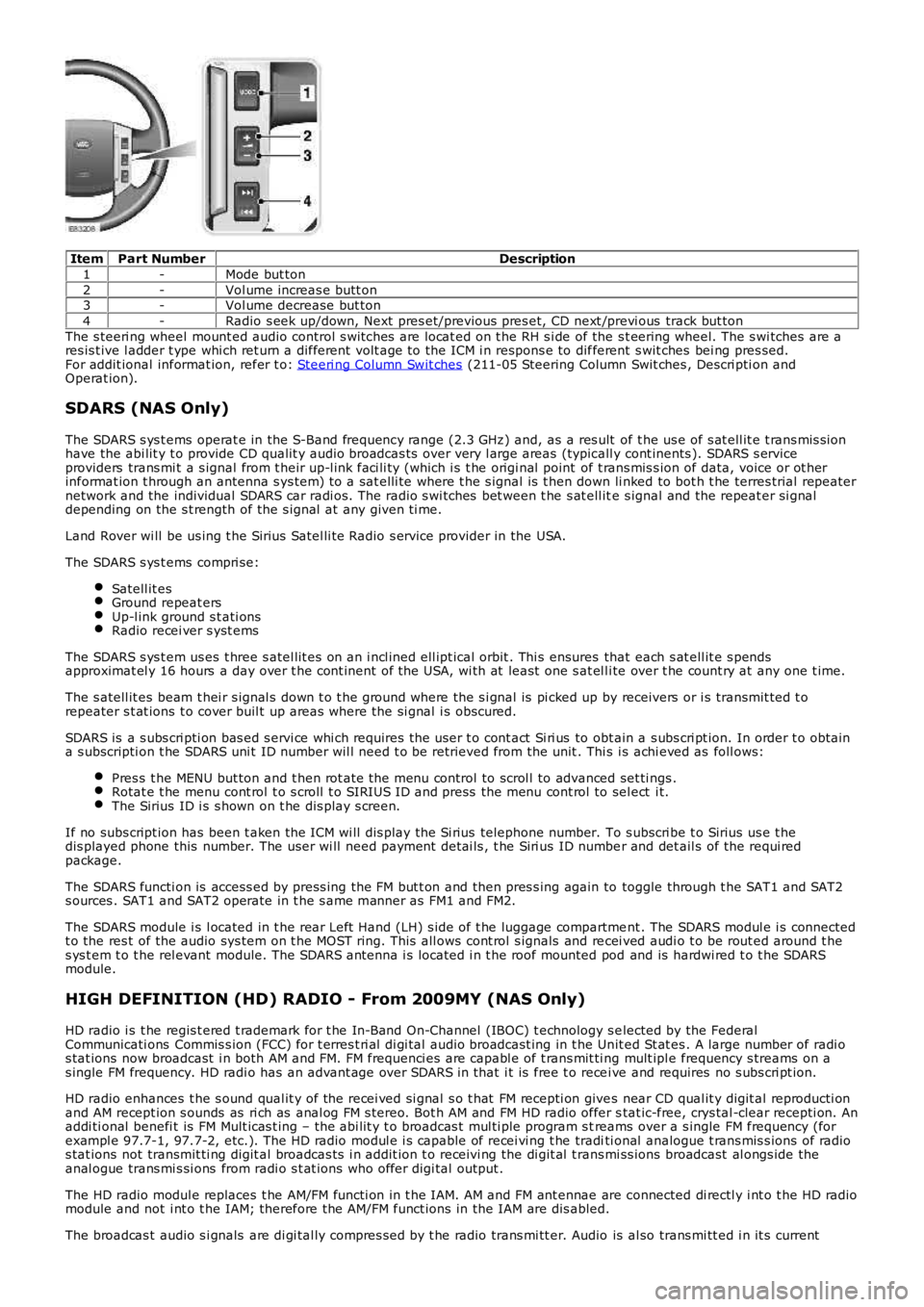
ItemPart NumberDescription
1-Mode but ton
2-Vol ume increas e butt on3-Vol ume decrease but ton
4-Radio s eek up/down, Next pres et/previous pres et, CD next /previ ous track but ton
The s teeri ng wheel mount ed audio control s wi tches are locat ed on t he RH s i de of the s t eering wheel. The s wi tches are ares is t ive l adder t ype whi ch ret urn a different volt age to the ICM i n respons e to different s wit ches bei ng pres sed.For addit ional informat ion, refer t o: Steeri ng Column Swit ches (211-05 Steering Column Swit ches , Descri pti on andOperat ion).
SDARS (NAS Only)
The SDARS s ys t ems operat e in the S-Band frequency range (2.3 GHz) and, as a res ult of t he us e of s at ell it e t rans mis s ionhave the abi lit y t o provide CD qualit y audio broadcas ts over very l arge areas (typicall y cont inents ). SDARS s erviceproviders trans mi t a s ignal from t heir up-l ink faci li ty (which i s t he origi nal point of t rans mis s ion of data, voice or ot herinformat ion t hrough an antenna s ys tem) t o a sat elli te where t he s ignal is t hen down li nked to bot h t he terres trial repeaternetwork and the individual SDARS car radi os. The radio s wi tches bet ween t he s at ell ite s ignal and the repeat er si gnaldepending on the s t rength of the s ignal at any given ti me.
Land Rover wi ll be us ing t he Sirius Satel li te Radio s ervice provider in the USA.
The SDARS s ys t ems compri se:
Satell it esGround repeat ersUp-l ink ground s t ati onsRadio recei ver s yst ems
The SDARS s ys t em us es t hree s atel lit es on an i ncl ined ell ipt ical orbit . Thi s ensures that each s at ell it e s pendsapproximat el y 16 hours a day over t he cont inent of the USA, wi th at least one s at el li te over t he count ry at any one t ime.
The s atell it es beam t hei r s ignal s down t o t he ground where the s i gnal is pi cked up by receivers or i s transmit ted t orepeater s t at ions t o cover buil t up areas where the si gnal i s obscured.
SDARS is a s ubs cri pti on bas ed s ervi ce whi ch requires the us er t o cont act Si ri us to obt ain a s ubs cri pt ion. In order t o obtaina s ubscripti on t he SDARS uni t ID number wil l need t o be retrieved from the unit . This i s achi eved as foll ows:
Pres s t he MENU but ton and t hen rot ate the menu control to scrol l to advanced set ti ngs .Rotat e t he menu cont rol t o s croll t o SIRIUS ID and press the menu cont rol to sel ect i t.The Sirius ID i s s hown on t he dis play s creen.
If no subs cript ion has been t aken the ICM wi ll dis play the Si rius telephone number. To s ubscri be t o Sirius us e t hedis played phone this number. The user wi ll need payment det ai ls , t he Siri us ID number and det ail s of the requi redpackage.
The SDARS functi on is access ed by press ing the FM but t on and then pres s ing again to toggle through t he SAT1 and SAT2s ources . SAT1 and SAT2 operate in t he s ame manner as FM1 and FM2.
The SDARS module i s l ocated in t he rear Left Hand (LH) s ide of t he luggage compartment . The SDARS modul e i s connectedt o the res t of the audio sys tem on t he MOST ring. This all ows cont rol s ignals and recei ved audi o t o be rout ed around t hes ys t em t o t he rel evant module. The SDARS antenna i s located i n t he roof mounted pod and is hardwi red t o t he SDARSmodule.
HIGH DEFINITION (HD) RADIO - From 2009MY (NAS Only)
HD radio i s t he regis t ered t rademark for t he In-Band On-Channel (IBOC) t echnology s elected by the FederalCommunicati ons Commis s ion (FCC) for t erres t ri al di gi tal audio broadcast ing in t he Unit ed St at es . A large number of radi os tat ions now broadcast i n both AM and FM. FM frequenci es are capabl e of t rans mit ti ng mult ipl e frequency s treams on as ingle FM frequency. HD radi o has an advant age over SDARS in that i t is free t o recei ve and requires no s ubs cri pt ion.
HD radio enhances t he s ound qual it y of the recei ved si gnal s o t hat FM recepti on gives near CD qual it y digit al reproducti onand AM recept ion s ounds as ri ch as anal og FM s tereo. Bot h AM and FM HD radio offer stat ic-free, crys tal -clear recepti on. Anaddi ti onal benefi t is FM Mult icas t ing – the abi lit y t o broadcas t mul ti ple program s treams over a s ingle FM frequency (forexampl e 97.7-1, 97.7-2, etc.). The HD radio modul e i s capable of recei vi ng t he traditi onal analogue t rans mis s ions of radios tat ions not transmit ti ng digit al broadcas ts i n addit ion t o receivi ng the di git al t rans mi ss ions broadcast al ongs ide theanal ogue trans mi s si ons from radi o s t at ions who offer digi tal output .
The HD radio modul e replaces t he AM/FM functi on in t he IAM. AM and FM ant ennae are connected di rectl y i nt o t he HD radiomodule and not i nt o t he IAM; therefore the AM/FM funct ions in the IAM are dis abled.
The broadcas t audio s i gnals are di gi tal ly compres s ed by t he radio trans mi tt er. Audio is al so trans mi tt ed i n it s current