2006 LAND ROVER FRELANDER 2 high beam
[x] Cancel search: high beamPage 1918 of 3229
5-Side turn s ignal l amp
6-Headlamp level ing modul e or Adapt ive Front l ighti ng Sys t em (AFS) control modul e
7-Bat tery Juncti on Box (BJB)8-Column s talk mult ifunct ion s wit ch
9-Revers e l amp s wit ch (Manual trans mi s si on only)
10-Light s wit ch module11-St op lamp swi tch
12-Front height s ens or (Xenon headlamps only)
13-Refl ect or14-Rear lamp as s embly
15-License plate lamps
16-Hi gh mounted s t op lamp17-Central Juncti on Box (CJB)
18-Front fog lamp
19-Headlamp as s embly
OVERVIEW
Three l evel s of ext eri or l ighti ng are avai lable dependi ng on vehicle s peci fi cat ion:
Halogen headl ampsBi-xenon Hi gh Int ensi ty Dis charge (HID) headl ampsBi-xenon HID Adapt ive Front li ghti ng Sys t em (AFS) headlamps .
A l ight s wit ch module i s located i n t he ins t rument panel and all ows t he driver t o s elect the appropri ate operat ion of t heexteri or li ght ing s ys tems .
The rear l amp as sembl ies cont ain si de lamps , s top lamps , revers e l amps , t urn s i gnal indi cat ors and rear fog lamps . OnNort h American Speci ficat ion (NAS) vehicles the rear l amp as s embly als o incl udes a side marker l amp. The rear lampas sembl ies requi re removal for bul b repl acement. Two reflect ors are mount ed in the rear bumper.
All vers ions of t he headl amps have impact res is t ant polycarbonat e l ens '. Removable covers at t he rear of t he headl ampsall ow for bulb replacement. The headlamps requi re removal for bul b repl acement.
The halogen headl amps have large complex surface reflectors to opt imis e t he beam patt erns i n l ow beam only. A hi ghbeam only refl ect or is l ocat ed on t he inboard s i de of the headlamp. Headl amp l evel ing on t he halogen headl amps ismanually adjust ed us ing a rot ary t humbwheel located i n t he li ght swi tch modul e which operat es leveling motors located i nt he headlamp.
The bi-functi on HID headl amps and the AFS headlamps us e a projector unit wit h a D1S xenon bulb whi ch operates i n bothlow and high beam. An addit ional hal ogen hi gh beam only refl ect or is l ocat ed on t he inboard s ide of t he headlamp.Headl amp l evel ing i s aut omat ic on t he HID headl amps . Front and rear hei ght sens ors are located on the Left Hand (LH)s ide of t he front and rear axl es. Thes e meas ure t he vehi cle at ti tude and a headlamp leveling modul e, which is locat ed ont he bul khead 'A' pi ll ar behind t he glovebox, aut omat icall y cont rol s t he headlamp vert ical al ignment.
Headl amp powerwas h i s a s t andard fi tment on HID headlamps .
Turn s i gnal indi cat ors and high and low beam functi ons are cont rol led from t he LH s teeri ng column mul ti functi on s wit ch.The t urn s ignal indicators have a lane change feat ure. A s ingle pres s and rel eas e of t he mult ifunct ion s wi tch i n eit herdirect ion wi ll operat e t he sel ect ed t urn s ignal indicators for 3 cycles .
The exteri or li ght ing i s cont rol led by t he CJB. The CJB i s t he main cont roll ing modul e for vehicle body s yst ems and i slocated behind the gl ovebox in the i nst rument panel.
The CJB provides circui t protect ion for al l ext eri or l ighti ng circui ts .
Exterior Bulb Typ e/Rating
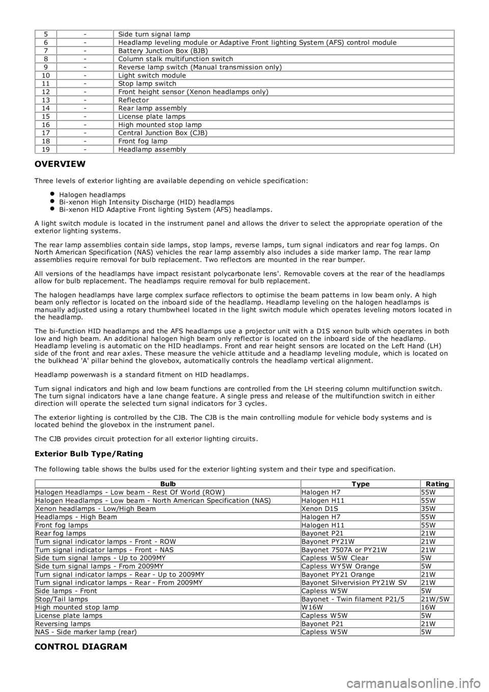
The fol lowing table shows t he bulbs us ed for t he exterior li ght ing sys tem and t hei r type and s peci fi cat ion.
BulbT ypeRating
Halogen Headlamps - Low beam - Rest O f W orl d (ROW )Halogen H755W
Halogen Headlamps - Low beam - Nort h American Specificati on (NAS)Halogen H1155WXenon headl amps - Low/Hi gh BeamXenon D1S35W
Headlamps - Hi gh BeamHalogen H755W
Front fog lampsHalogen H1155WRear fog l ampsBayonet P2121W
Turn si gnal i ndi cat or lamps - Front - ROWBayonet PY 21W21W
Turn si gnal i ndi cat or lamps - Front - NASBayonet 7507A or PY 21W21WSide turn s ignal l amps - Up t o 2009MYCapl ess W 5W Clear5W
Side turn s ignal l amps - From 2009MYCapl ess W Y 5W Orange5W
Turn si gnal i ndi cat or lamps - Rear - Up t o 2009MYBayonet PY 21 Orange21WTurn si gnal i ndi cat or lamps - Rear - From 2009MYBayonet Silvervi si on PY 21W SV21W
Side lamps - FrontCapl ess W 5W5W
St op/Tai l lampsBayonet - Twin fil ament P21/521W /5WHi gh mount ed s t op lampW 16W16W
License plate lampsCapl ess W 5W5W
Revers ing l ampsBayonet P2121WNAS - Si de marker lamp (rear)Capl ess W 5W5W
CONTROL DIAGRAM
Page 1920 of 3229
10-RH s i de turn s ignal lamp
11-Licens e pl ate lamps
12-LH rear l amp as s embl y13-RH rear lamp as s embly
14-LH headlamp as s embly
15-AFS cont rol module16-Headl amp l evel ing mot or
17-RH headlamp as s embly
18-Steering wheel modul e19-LH s t eering column mult ifunct ion s wit ch
20-High mount ed s top lamp
21-Central Junct ion Box (CJB)22-Revers e s wit ch (manual transmis si on only)
23-Stoplamp s wit ch
24-Rain/light s ensor25-Hazard flas her s wi tch
26-Light s wit ch modul e
27-Fuse 15A (F33)
CENTRAL JUNCTION BOX (CJB)
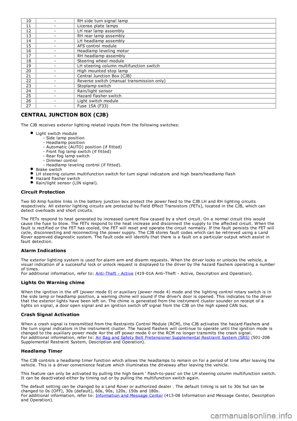
The CJB receives exteri or li ght ing relat ed inputs from t he fol lowing s wi tches:
Light s wit ch modul e- Side l amp pos it ion- Headlamp pos it ion- Automat ic (AUTO) posi ti on (if fi tt ed)- Front fog lamp swi tch (if fit ted)- Rear fog l amp s wit ch- Dimmer cont rol- Headlamp l evel ing control (if fit ted).Brake s wi tchLH s t eering column mult ifunct ion s wit ch for t urn si gnal i ndi cat ors and hi gh beam/headl amp flas hHazard flas her s wi tchRain/light s ensor (LIN si gnal ).
Circuit Protection
Two 60 Amp fus ibl e li nks in t he batt ery junct ion box protect the power feed to the CJB LH and RH li ght ing ci rcuit sres pect ively. All ext erior l ighti ng ci rcuit s are prot ect ed by Field Effect Trans is t ors (FETs ), l ocat ed in the CJB, which candetect overloads and s hort circuit s .
The FETs res pond to heat generated by increased current fl ow caus ed by a s hort ci rcuit . On a normal ci rcuit t his woul dcaus e t he fus e to bl ow. The FETs respond t o t he heat i ncrease and di s connect t he s uppl y t o t he affect ed ci rcuit . W hen t hefaul t is rect ified or t he FET has cool ed, t he FET wil l res et and operate t he circui t normall y. If t he faul t pers is ts the FET wi llcycle, di sconnect ing and reconnect ing t he power supply. The CJB s tores fault codes which can be ret rieved usi ng a LandRover approved diagnost ic sys tem. The fault code wil l identi fy t hat there is a fault on a part icular out put which as si s t infaul t det ect ion.
Alarm Indications
The exteri or li ght ing s ys tem is us ed for al arm arm and dis arm reques ts . W hen t he driver l ocks or unlocks the vehicle, avis ual i ndicat ion of a s uccess ful l ock or unlock reques t is di spl ayed t o t he dri ver by the hazard flas hers operat ing a numberof ti mes .For addit ional informat ion, refer t o: Anti -Theft - Act ive (419-01A Anti -Theft - Acti ve, Des cri pt ion and Operati on).
Lights On Warning chime
W hen t he i gni ti on in the off (power mode 0) or auxi liary (power mode 4) mode and the l ighti ng cont rol rotary swit ch is i nt he si de lamp or headlamp posi ti on, a warning chime wi ll s ound i f the driver's door is opened. This indicates t o t he dri vert hat t he exterior li ght s have been left on. The chime is generat ed from t he i ns t rument clus ter s ounder on receipt of ali ght s on s i gnal , a door open s ignal and an ignit ion swi tch off s ignal from t he CJB on the hi gh s peed CAN bus.
Crash Signal Activation
W hen a crash s ignal i s t rans mit ted from t he Rest rai nts Cont rol Modul e (RCM), t he CJB act ivat es the hazard flas hers andt he turn s ignal indicators in t he i ns t rument clus ter. The hazard fl ashers wil l continue to operate unt il t he ignit ion mode ischanged t o t he auxi liary power mode 4or the off power mode 0 or the RCM no longer trans mi ts the cras h si gnal .For addit ional informat ion, refer t o: Air Bag and Safet y Belt Pretens ioner Supplement al Res traint Syst em (SRS) (501-20BSuppl ement al Rest rai nt Sys tem, Des cri pti on and Operati on).
Headlamp Timer
The CJB cont rol s a headl amp t imer funct ion whi ch allows the headlamps t o remain on for a peri od of ti me after leaving t hevehi cl e. Thi s is a dri ver conveni ence feat ure which il lumi nat es t he dri veway after leaving t he vehicle.
This feat ure can onl y be acti vat ed by pulli ng t he high beam ' flas h-t o-pas s' on t he LH s t eering column mult ifunct ion s wi tch.It can be deacti vat ed eit her by ti ming out or by pull ing t he mul ti funct ion swi tch again.
The default s ett ing can be changed by a Land Rover or authorized deal er . The default t imi ng is s et t o 30s but can bechanged t o 0s (OFF), 30s (defaul t), 60s , 90s , 120s , 150s and 180s .For addit ional informat ion, refer t o: Informat ion and Mes s age Cent er (413-08 Informat ion and Mes s age Cent er, Des cript ionand Operat ion).
Page 1922 of 3229
The automat ic headlamp s ys tem uses a li ght s ens or and t he CJB, which are connect ed via the LIN bus t o cont rol t heheadl amp funct ional it y.
A l ight s ens or is incorporated in t he rai n/l ight s ens or located on the i nsi de of the windshi el d, bel ow t he rear view mirror.The wiper s yst em al s o uses the rain/l ight s ens or for aut omati c wiper operati on.For addit ional informat ion, refer t o: W i pers and W as hers (501-16 W ipers and W as hers , Des cri pti on and Operati on).
The li ght sens or meas ures the ambi ent l ight around t he vehi cl e i n a vert ical direct ion and als o the angular li ght l evel fromt he front of t he vehi cle. The rai n/li ght sens or us es vehicle s peed s ignals , wiper s wit ch posi ti on and the park posi ti on of thefront wipers to control the s ys tem.
The automat ic headlamp operat ion us es ambient l ight levels whi ch are moni tored by phot odiodes incorporat ed in t herai n/l ight sens or. The rain/l ight s ens or s ends a li ght s on/off request t o t he CJB on t he LIN bus , which res ponds bys wit chi ng on t he low beam headl amps, front s ide l amps, l icense plate lamps and rear t ail l amps. The aut omat ic headlampsare act ivated under the foll owing condi ti ons :
Twil ightDarknessRainTunnel sUnderground or mult is t ori ed car parks .
Operat ion of t he aut omat ic headl amps requires t he ignit ion t o be on (power mode 6), the l ighti ng cont rol rot ary swi tch t obe i n the 'AUTO' pos it ion and a li ght s on reques t s ignal from t he li ght sens or.
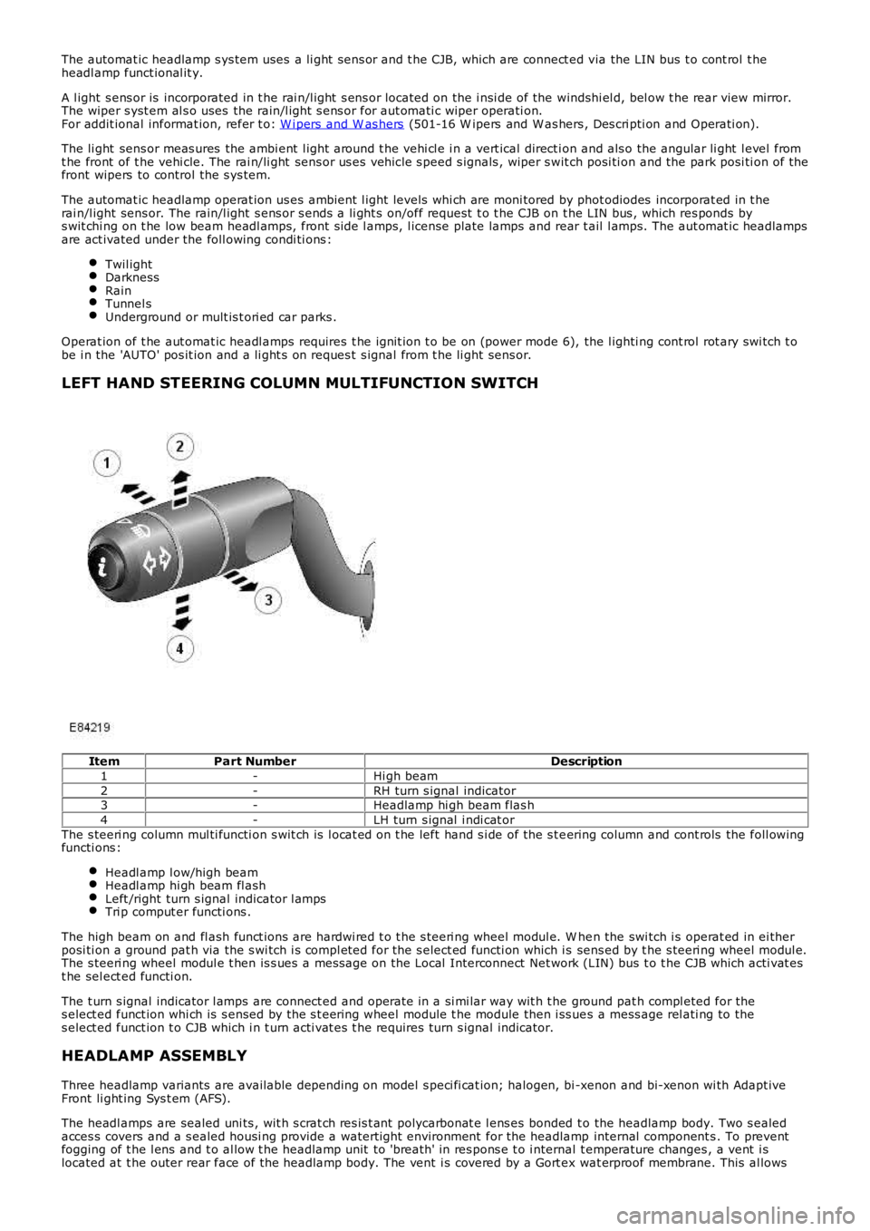
LEFT HAND STEERING COLUMN MULTIFUNCTION SWITCH
ItemPart NumberDescription
1-Hi gh beam
2-RH turn s ignal indicator3-Headlamp hi gh beam flas h
4-LH turn s ignal i ndi cat or
The s teeri ng column mul ti functi on s wit ch is l ocat ed on t he left hand s i de of the s t eering column and cont rols the foll owingfuncti ons :
Headl amp l ow/high beamHeadl amp hi gh beam fl ashLeft /right turn s ignal indicator l ampsTri p comput er functi ons .
The high beam on and fl ash funct ions are hardwi red t o t he s teeri ng wheel modul e. W hen the swi tch i s operat ed in ei therposi ti on a ground pat h via the s wi tch i s compl eted for the s elect ed functi on which is sens ed by t he s teeri ng wheel modul e.The s teeri ng wheel modul e t hen is s ues a mes sage on the Local Interconnect Net work (LIN) bus t o t he CJB which acti vat est he sel ect ed functi on.
The t urn s ignal indicator l amps are connect ed and operate in a si mi lar way wit h t he ground pat h compl eted for thes elect ed funct ion whi ch is s ensed by the s t eering wheel module t he module then i ss ues a mess age rel ati ng to thes elect ed funct ion t o CJB which i n t urn acti vat es t he requires turn s ignal indicator.
HEADLAMP ASSEMBLY
Three headlamp variants are available depending on model s peci fi cat ion; halogen, bi -xenon and bi-xenon wi th Adapt iveFront li ght ing Sys t em (AFS).
The headl amps are sealed uni ts , wit h s crat ch res is t ant polycarbonat e l ens es bonded to the headlamp body. Two s ealedacces s covers and a s ealed housi ng provide a waterti ght environment for the headlamp internal component s . To preventfogging of t he l ens and t o al low t he headlamp unit to 'breath' in res pons e t o i nternal t emperature changes , a vent i slocated at t he outer rear face of the headlamp body. The vent i s covered by a Gort ex wat erproof membrane. This al lows
Page 1925 of 3229
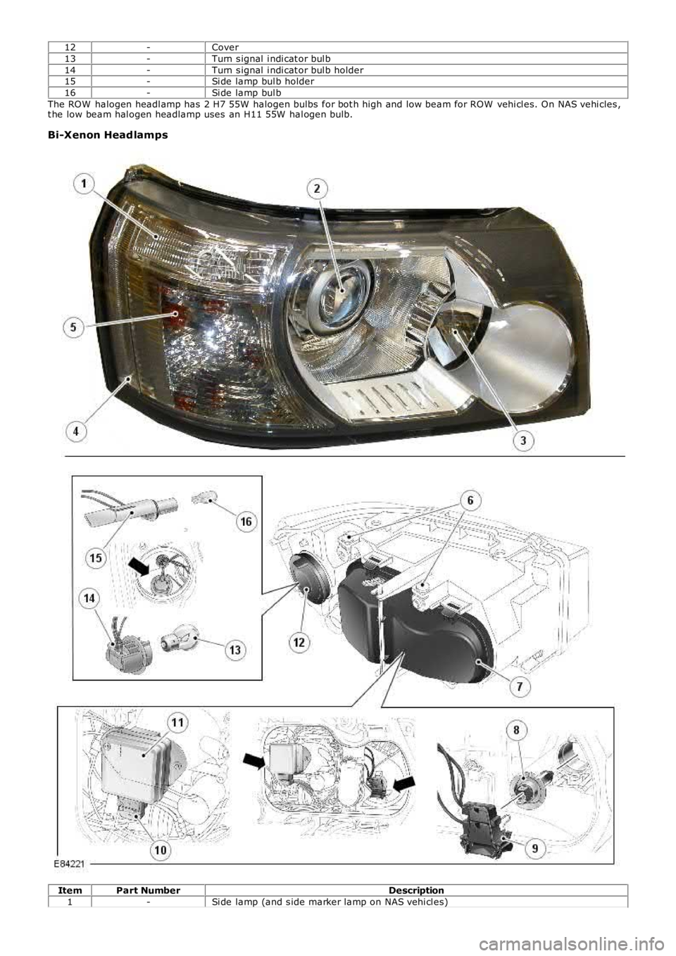
12-Cover
13-Turn s ignal i ndi cat or bul b
14-Turn s ignal i ndi cat or bul b holder15-Si de lamp bul b holder
16-Si de lamp bul b
The ROW halogen headl amp has 2 H7 55W halogen bulbs for bot h high and low beam for ROW vehi cl es. On NAS vehi cles ,t he low beam hal ogen headlamp uses an H11 55W hal ogen bulb.
Bi-Xenon Head lamps
ItemPart NumberDescription
1-Si de lamp (and s ide marker lamp on NAS vehi cl es)
Page 1926 of 3229
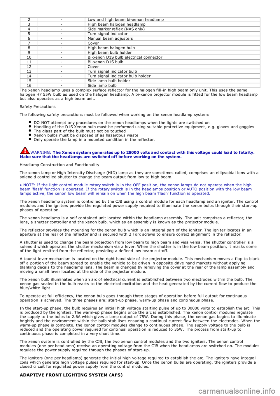
2-Low and hi gh beam bi-xenon headlamp
3-Hi gh beam halogen headl amp
4-Si de marker reflex (NAS only)5-Turn s ignal i ndi cat or
6-Manual beam adjus ters
7-Cover8-Hi gh beam halogen bulb
9-Hi gh beam bulb hol der
10-Bi -xenon D1S bulb el ect ri cal connector11-Bi -xenon D1S bulb
12-Cover
13-Turn s ignal i ndi cat or bul b14-Turn s ignal i ndi cat or bul b holder
15-Si de lamp bul b holder
16-Si de lamp bul bThe xenon headlamp uses a compl ex s urface reflect or for the hal ogen fil l-in hi gh beam only uni t. This us es t he s amehalogen H7 55W bul b as us ed on t he halogen headl amp. A bi-xenon projector module i s fit ted for the l ow beam headlampbut als o operates as a high beam uni t.
Safet y Precaut ions
The fol lowing safety precauti ons mus t be fol lowed when worki ng on t he xenon headlamp sys tem:
DO NOT att empt any procedures on t he xenon headlamps when t he li ghts are s wit ched onHandl ing of t he D1S Xenon bulb mus t be performed usi ng s uit abl e prot ect ive equipment, e.g. gloves and gogglesThe glas s part of t he bulb mus t not be t ouchedXenon bul bs mus t be dis posed of as hazardous was teOnly operat e t he lamp in a mounted condit ion i n t he reflect or.
W ARNING: T he Xenon system generates up to 28000 volts and contact w ith this voltage could lead to fatality.Make sure that the headlamps are sw itched off before w orking on the system.
Headl amp Cons truct ion and Funct ionali ty
The xenon lamp or Hi gh Int ens i ty Di s charge (HID) lamp as they are s ometi mes cal led, compris es an el li ps oidal lens wi th as olenoi d control led s hutt er to change t he beam output from low to hi gh beam.
• NOTE: If the l ight cont rol module rot ary s wit ch is in t he OFF pos it ion, the xenon lamps do not operat e when t he highbeam 'flas h' functi on is operat ed. If t he rot ary s wi tch i s in the headlamps pos it ion or AUTO pos it ion wi th the low beamlamps act ive, the xenon low beam wi ll remai n on when t he high beam 'flas h' funct ion i s operated.
The xenon headlamp sys t em i s cont roll ed by t he CJB usi ng a control modul e for each headl amp and an i gni ter. The cont rolmodules and t he ignit ers provide t he regulat ed power s upply requi red t o i ll uminate the xenon bulbs t hrough t hei r st art -upphas es of operat ion.
The xenon headlamp is a sel f cont ai ned unit located wit hi n t he headl amp as sembl y. The uni t compris es a refl ect or, t helens , a s hutt er controll er and t he xenon bul b, which as an as s embly i s known as the projector module.
The reflector provides t he mounti ng for t he xenon bul b which i s an i ntegral part of t he ignit er. The i gni ter l ocat es in anapert ure at t he rear of the refl ect or and is s ecured wi th 2 Torx s crews t o ens ure correct al ignment in the refl ect or.
A s hutt er is us ed t o change t he beam projecti on from l ow beam t o hi gh beam and vis a vers a. The s hut t er controller i s as olenoi d whi ch operat es t he s hut ter mechani s m vi a a l ever. W hen t he shut ter i s in the l ow beam pos it ion, it mas ks s omeof the light emi tt ed from the refl ect or, providi ng a defi ned low beam cut -off.
A t ouri st l ever mechani s m i s located on the right hand s ide of t he project or modul e. Thi s mechanis m moves a flap t o blankoff a porti on of the beam s pread to enabl e the vehicl e to be dri ven in opposi te dri ve hand markets wit hout applyingblanking decal s t o t he headlamp lens . The beam is changed by removing the cover at the rear of t he lamp ass embly andmoving a small lever locat ed at t he s ide of t he project or modul e.
The xenon bul b il lumi nat es when an arc of el ect ri cal current is es tabli s hed bet ween t wo electrodes wit hi n t he bulb. Thexenon gas s ealed i n t he bulb react s t o t he elect rical excit at ion and the heat generated by t he current flow to produce theblue/whi te li ght .
To operat e at ful l effi ci ency, the xenon bulb goes t hrough t hree s t ages of operat ion before ful l out put for cont inuousoperati on is achieved. The three phas es are; s t art -up phas e, warm-up phas e and continuous phas e.
In the st art -up phas e, the bul b requires an ini ti al hi gh vol tage s t art ing puls e of up t o 30000 volt s to est ablis h the arc. Thisis produced by t he i gni ters. The warm-up phas e begins once t he arc i s est abli shed. The xenon control modul es regulat et he supply to the bulbs t o 2.6A which gi ves a lamp out put of 75W . During t his phas e, the xenon gas begi ns to il luminat ebri ght ly and the environment wi thi n t he bul b s t abi lis es ens uring a cont inual current fl ow bet ween the el ect rodes. W hen thewarm-up phas e is compl et e, the xenon control modul es change t o cont inuous phas e. The s uppl y vol tage t o t he bulb i sreduced and the operat ing power requi red for conti nual operat ion i s reduced to 35W . The proces s from s tart-up t ocont inuous phas e i s complet ed in a very s hort t ime.
The xenon sys tem is cont roll ed by t he CJB, t he two xenon control modul es and the two ignit ers . The xenon controlmodules (one per headlamp) receive an operati ng vol tage from the CJB when the headlamps are s wit ched on. The modulesregulat e t he power s upply requi red t hrough t he phas es of s tart-up.
The ignit ers (one per headl amp) generat e t he ini ti al hi gh vol tage requi red t o es t ablis h t he arc. The ignit ers have i ntegralcoi ls whi ch generate hi gh vol tage pul ses requi red for s tart -up. Once t he xenon bul bs are operat ing, the ignit ers provi de aclos ed ci rcuit for regulat ed power s upply from the control modul es.
ADAPTIVE FRONT LIGHTING SYSTEM (AFS)
Page 1959 of 3229
Publi s hed: 11-May-2011
Daytime Running Lamps (DRL) - Daytime Running Lamps (DRL)
Des cript ion and Operat ion
OVERVIEW
DRL us e t he ful l i ntens it y low beam headl amps which are permanentl y il lumi nat ed when t he vehi cl e i s being dri ven. DRLare us ed i n a number of market s and there are 2 s ys t ems t o cover t hes e markets .
For addit ional informat ion, refer t o: Ext eri or Li ght ing (417-01 Ext erior Light ing, Descri pti on and Operat ion).
DRL CANADIAN MARKET
DRL for t his market use full i ntens it y low beam headl amps. The s i de marker lamps , t ai l lamps and l icens e pl ate lamps wi llbe on, but ins trument cl us t er ill uminat ion wi ll be off. DRL are act ive when t he followi ng paramet ers are met:
PARK is not s elect ed on automat ic t rans mis s ion s elect or l everPower mode 6 (ignit ion on) detected by the auxil iary juncti on boxHandbrake is not applied.
• NOTE: If the rotary s wit ch on the light s wit ch module is moved t o t he headl amp posi ti on, DRL are deacti vat ed andnormal s ide l amp and headlamp funct ionali ty i s operat ional .
• NOTE: Adapt ive Front light ing Sys tem (AFS) (where fit ted) is non-funct ional when the DRL are act ive unles s t he rot arys wit ch on t he li ght s wi tch module is moved t o t he headl amp pos it ion.
• NOTE: W hen DRL are acti ve, t he headl amp flas h funct ion us ing t he left hand st eeri ng col umn mul ti funct ion swi tch willoperate normall y.
• NOTE: W hen DRL are acti ve, t he headl amp powerwas h funct ion i s non-funct ional , unles s the rotary s wit ch on t he li ghts wit ch module i s moved t o the headlamp pos i ti on.
The high beam headlamp functi on usi ng t he left hand s t eering column s talk swi tch will be deacti vat ed. W hen the sel ect orlever is i n t he PARK posi ti on on automat ic trans mi ss i on vehi cl es, DRL are t urned off. This i s to reduce bat t ery dis chargeduri ng long peri ods of engine idli ng in cold cl imat e condi ti ons. W hen the s elect or lever i s moved from t he PARK pos it ion,normal DRL funct ionalit y i s res t ored.
W hen t he handbrake is appli ed, DRL are t urned off t o reduce bat tery dis charge.
DRL DENMARK, HOLLAND, NORWAY, SWEDEN, FINLAND AND POLAND
• NOTE: DRL for Pol and is on vehicles from 2008MY .
DRL for t hese market s use full i ntens it y low beam headl amps. Si de lamps and l icense pl ate lamps wi ll be on, butins t rument clus ter il lumi nat ion will be off. DRL are acti ve when the foll owing paramet ers are met :
Power mode 6 (ignit ion on) detected by the auxil iary juncti on boxThe rot ary s wi tch on t he l ight s wit ch modul e i s in the off pos it ion.
• NOTE: W hen DRL are acti ve, t he headl amp flas h funct ion us ing t he left hand st eeri ng col umn mul ti funct ion swi tch willoperate normall y. The hi gh beam headlamp funct ion us ing the l eft hand s teeri ng column s t alk s wit ch wi ll be deact ivated.
• NOTE: W hen DRL are acti ve, t he headl amp powerwas h funct ion i s non-funct ional , unles s the rotary s wit ch on t he li ghts wit ch module i s moved t o the headlamp pos i ti on.
If the rotary s wit ch on the light s wit ch module i s moved t o t he s ide l amp or headl amp posi ti ons , DRL are deact ivated andnormal s ide l amp and headlamp funct ionali ty i s operat ional .
Page 2741 of 3229
21
Quick start
R
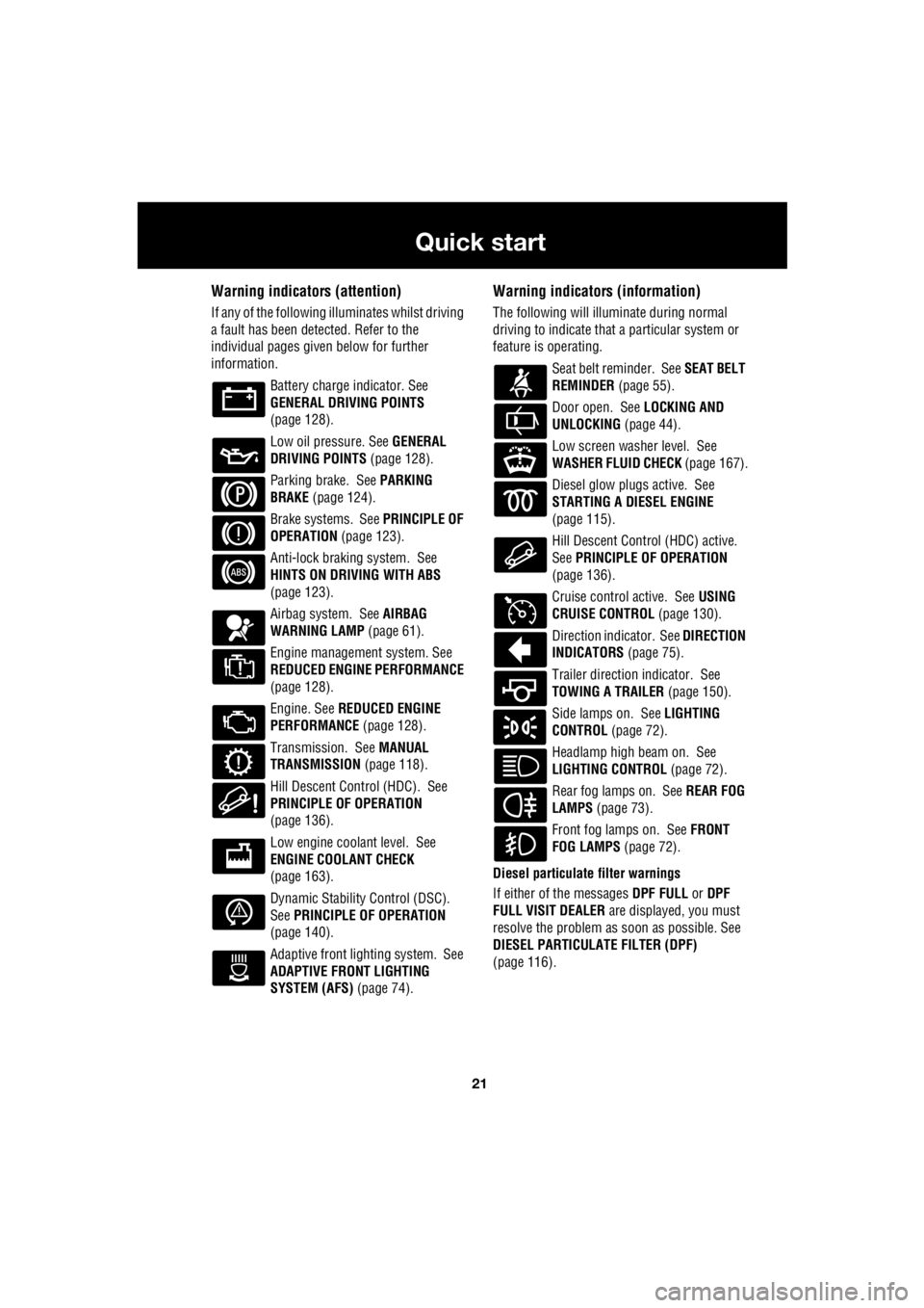
Warning indicators (attention)
If any of the following illuminates whilst driving
a fault has been detected. Refer to the
individual pages give n below for further
information.
Battery charge indicator. See
GENERAL DRIVING POINTS
(page 128).
Low oil pressure. See GENERAL
DRIVING POINTS (page 128).
Parking brake. See PARKING
BRAKE (page 124).
Brake systems. See PRINCIPLE OF
OPERATION (page 123).
Anti-lock braking system. See
HINTS ON DRIVING WITH ABS
(page 123).
Airbag system. See AIRBAG
WARNING LAMP (page 61).
Engine management system. See
REDUCED ENGINE PERFORMANCE
(page 128).
Engine. See REDUCED ENGINE
PERFORMANCE (page 128).
Transmission. See MANUAL
TRANSMISSION (page 118).
Hill Descent Control (HDC). See
PRINCIPLE OF OPERATION
(page 136).
Low engine coolant level. See
ENGINE COOLANT CHECK
(page 163).
Dynamic Stability Control (DSC).
See PRINCIPLE OF OPERATION
(page 140).
Adaptive front lighting system. See
ADAPTIVE FRONT LIGHTING
SYSTEM (AFS) (page 74).
Warning indicators (information)
The following will illuminate during normal
driving to indicate that a particular system or
feature is operating.
Seat belt reminder. See SEAT BELT
REMINDER (page 55).
Door open. See LOCKING AND
UNLOCKING (page 44).
Low screen washer level. See
WASHER FLUID CHECK (page 167).
Diesel glow plugs active. See
STARTING A DIESEL ENGINE
(page 115).
Hill Descent Control (HDC) active.
See PRINCIPLE OF OPERATION
(page 136).
Cruise control active. See USING
CRUISE CONTROL (page 130).
Direction indicator. See DIRECTION
INDICATORS (page 75).
Trailer direction indicator. See
TOWING A TRAILER (page 150).
Side lamps on. See LIGHTING
CONTROL (page 72).
Headlamp high beam on. See
LIGHTING CONTROL (page 72).
Rear fog lamps on. See REAR FOG
LAMPS (page 73).
Front fog lamps on. See FRONT
FOG LAMPS (page 72).
Diesel particulate filter warnings
If either of the messages DPF FULL or DPF
FULL VISIT DEALER are displayed, you must
resolve the problem as soon as possible. See
DIESEL PARTICULATE FILTER (DPF)
(page 116).
Page 2743 of 3229
23
Quick start
R
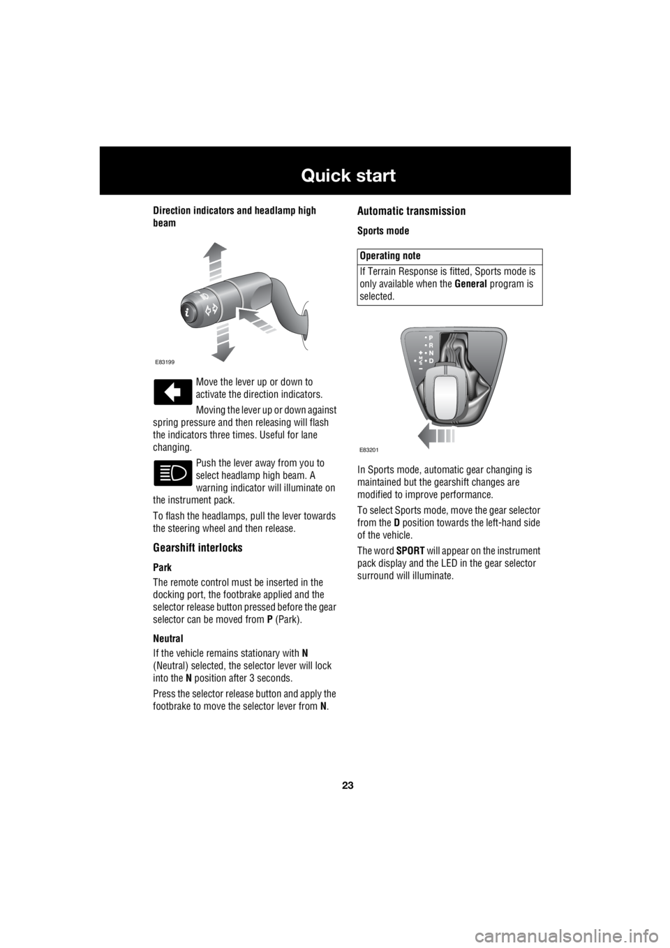
Direction indicators and headlamp high
beam
Move the lever up or down to
activate the direction indicators.
Moving the lever up or down against
spring pressure and then releasing will flash
the indicators three times. Useful for lane
changing.
Push the lever away from you to
select headlamp high beam. A
warning indicator will illuminate on
the instrument pack.
To flash the headlamps, pull the lever towards
the steering wheel and then release.
Gearshift interlocks
Park
The remote control must be inserted in the
docking port, the footbrake applied and the
selector release button pr essed before the gear
selector can be moved from P (Park).
Neutral
If the vehicle remains stationary with N
(Neutral) selected, the selector lever will lock
into the N position after 3 seconds.
Press the selector rele ase button and apply the
footbrake to move the selector lever from N.
Automatic transmission
Sports mode
In Sports mode, automatic gear changing is
maintained but the gearshift changes are
modified to improve performance.
To select Sports mode, move the gear selector
from the D position towards the left-hand side
of the vehicle.
The word SPORT will appear on the instrument
pack display and the LED in the gear selector
surround will illuminate.
E83199
Operating note
If Terrain Response is fi tted, Sports mode is
only available when the General program is
selected.
E83201