2006 LAND ROVER FRELANDER 2 brake sensor
[x] Cancel search: brake sensorPage 54 of 3229
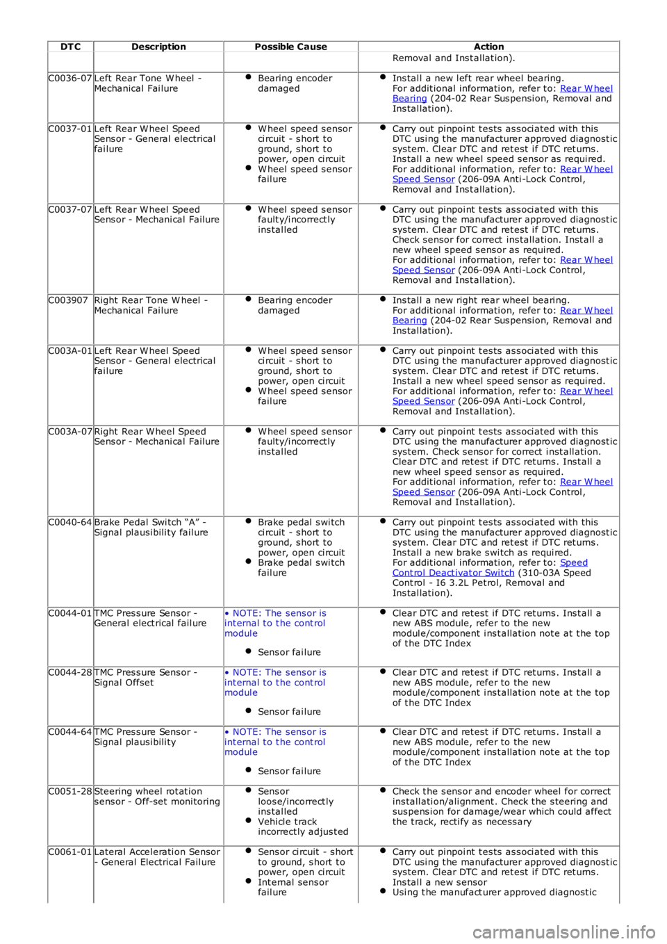
DT CDescriptionPossible CauseAction
Removal and Ins t allat ion).
C0036-07Left Rear Tone W heel -Mechanical Fai lureBearing encoderdamagedIns tal l a new l eft rear wheel bearing.For addit ional informati on, refer t o: Rear W heelBearing (204-02 Rear Sus pensi on, Removal andIns tal lati on).
C0037-01Left Rear W heel SpeedSens or - General electricalfai lure
W heel speed s ensorci rcuit - s hort t oground, s hort t opower, open ci rcuitW heel speed s ensorfail ure
Carry out pi npoi nt t es ts as s oci ated wi th thi sDTC usi ng t he manufacturer approved diagnost icsys tem. Cl ear DTC and ret est i f DTC ret urns .Ins tal l a new wheel speed s ensor as requi red.For addit ional informati on, refer t o: Rear W heelSpeed Sens or (206-09A Anti -Lock Control ,Removal and Ins t allat ion).
C0037-07Left Rear W heel SpeedSens or - Mechani cal FailureW heel speed s ensorfault y/i ncorrect lyins tal led
Carry out pi npoi nt t es ts as s oci ated wi th thi sDTC usi ng t he manufacturer approved diagnost icsys tem. Cl ear DTC and ret est i f DTC ret urns .Check s ensor for correct ins tall ati on. Inst all anew wheel s peed s ens or as required.For addit ional informati on, refer t o: Rear W heelSpeed Sens or (206-09A Anti -Lock Control ,Removal and Ins t allat ion).
C003907Right Rear Tone W heel -Mechanical Fai lureBearing encoderdamagedIns tal l a new right rear wheel beari ng.For addit ional informati on, refer t o: Rear W heelBearing (204-02 Rear Sus pensi on, Removal andIns tal lati on).
C003A-01Left Rear W heel SpeedSens or - General electricalfai lure
W heel speed s ensorci rcuit - s hort t oground, s hort t opower, open ci rcuitW heel speed s ensorfail ure
Carry out pi npoi nt t es ts as s oci ated wi th thi sDTC usi ng t he manufacturer approved diagnost icsys tem. Cl ear DTC and ret est i f DTC ret urns .Ins tal l a new wheel speed s ensor as requi red.For addit ional informati on, refer t o: Rear W heelSpeed Sens or (206-09A Anti -Lock Control ,Removal and Ins t allat ion).
C003A-07Right Rear W heel SpeedSens or - Mechani cal FailureW heel speed s ensorfault y/i ncorrect lyins tal led
Carry out pi npoi nt t es ts as s oci ated wi th thi sDTC usi ng t he manufacturer approved diagnost icsys tem. Check s ens or for correct i nst all ati on.Clear DTC and ret est i f DTC ret urns . Ins t all anew wheel s peed s ens or as required.For addit ional informati on, refer t o: Rear W heelSpeed Sens or (206-09A Anti -Lock Control ,Removal and Ins t allat ion).
C0040-64Brake Pedal Swi tch “A” -Signal pl ausi bili ty fail ureBrake pedal s wi tchci rcuit - s hort t oground, s hort t opower, open ci rcuitBrake pedal s wi tchfail ure
Carry out pi npoi nt t es ts as s oci ated wi th thi sDTC usi ng t he manufacturer approved diagnost icsys tem. Cl ear DTC and ret est i f DTC ret urns .Ins tal l a new brake s wi tch as requi red.For addit ional informati on, refer t o: SpeedCont rol Deact ivat or Swi tch (310-03A SpeedCont rol - I6 3.2L Pet rol, Removal andIns tal lati on).
C0044-01TMC Pres s ure Sens or -General elect rical fail ure• NOTE: The s ens or isint ernal t o t he cont rolmodul e
Sens or fai lure
Clear DTC and ret est i f DTC ret urns . Ins t all anew ABS module, refer to the newmodul e/component i ns t allat ion not e at t he topof t he DTC Index
C0044-28TMC Pres s ure Sens or -Signal Offset• NOTE: The s ens or isint ernal t o t he cont rolmodul e
Sens or fai lure
Clear DTC and ret est i f DTC ret urns . Ins t all anew ABS module, refer to the newmodul e/component i ns t allat ion not e at t he topof t he DTC Index
C0044-64TMC Pres s ure Sens or -Signal pl ausi bili ty• NOTE: The s ens or isint ernal t o t he cont rolmodul e
Sens or fai lure
Clear DTC and ret est i f DTC ret urns . Ins t all anew ABS module, refer to the newmodul e/component i ns t allat ion not e at t he topof t he DTC Index
C0051-28Steering wheel rot at ions ens or - Off-set moni toringSens orloos e/incorrect lyins tal ledVehi cl e t rackincorrect ly adjus t ed
Check t he s ens or and encoder wheel for correctins tall ati on/ali gnment . Check t he s teering andsus pens i on for damage/wear which could affectthe t rack, recti fy as necess ary
C0061-01Lateral Accel erati on Sensor- General Electrical Fail ureSens or ci rcuit - s hortto ground, s hort t opower, open ci rcuitInt ernal sens orfail ure
Carry out pi npoi nt t es ts as s oci ated wi th thi sDTC usi ng t he manufacturer approved diagnost icsys tem. Cl ear DTC and ret est i f DTC ret urns .Ins tal l a new s ensorUsi ng t he manufact urer approved diagnost ic
Page 78 of 3229
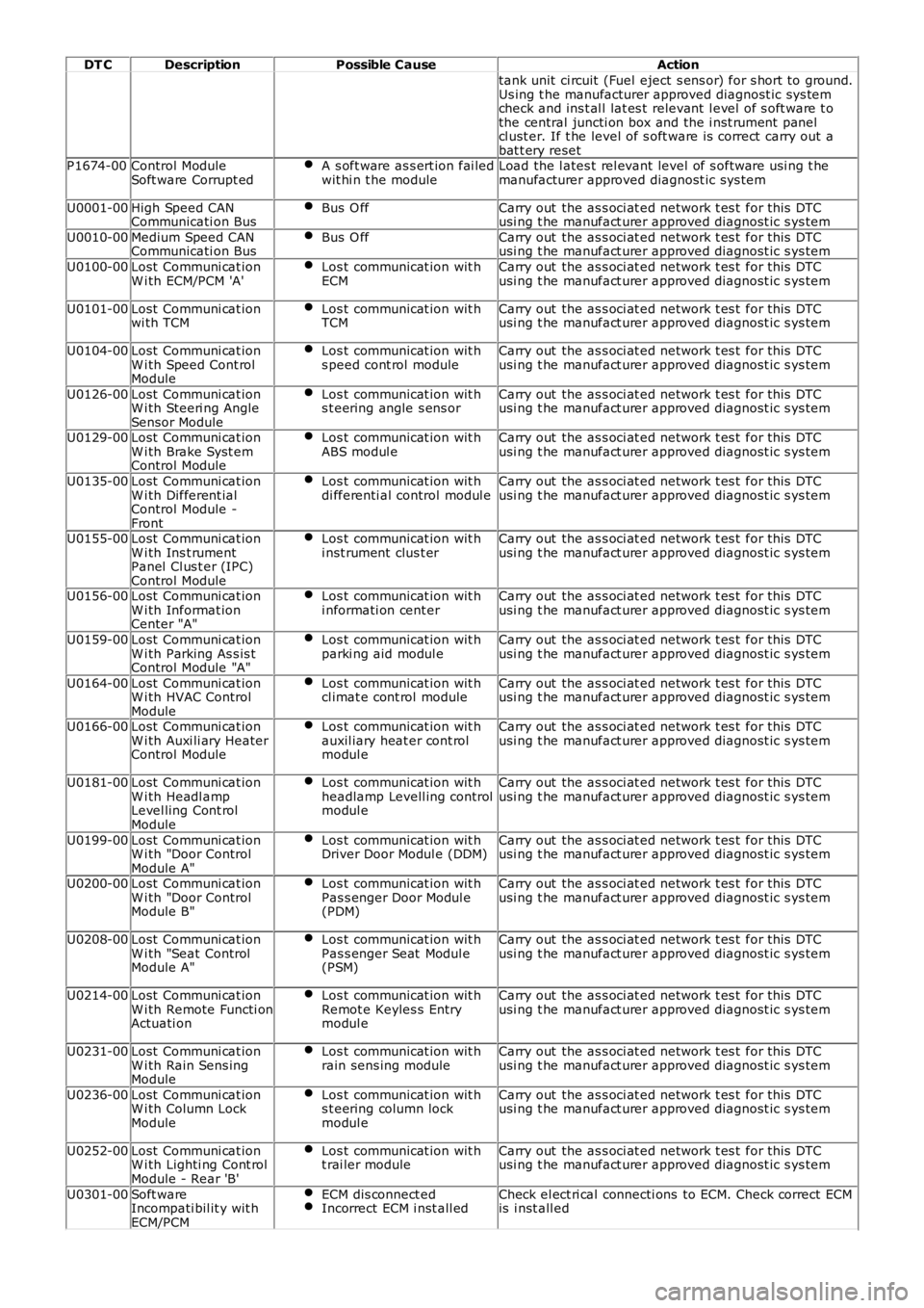
DT CDescriptionPossible CauseAction
tank unit ci rcuit (Fuel eject s ens or) for s hort to ground.Us ing t he manufacturer approved diagnost ic sys temcheck and ins t al l lat es t relevant l evel of s oft ware t othe central juncti on box and the i nst rument panelcl ust er. If t he level of s oft ware is correct carry out abat t ery resetP1674-00Control ModuleSoft ware Corrupt edA s oft ware as s ert ion fai ledwit hi n t he moduleLoad the l ates t rel evant level of s oftware usi ng t hemanufacturer approved diagnost ic sys tem
U0001-00High Speed CANCommunicati on BusBus O ffCarry out the as s oci at ed network t es t for this DTCusi ng t he manufact urer approved diagnost ic s ys tem
U0010-00Medium Speed CANCommunicati on BusBus O ffCarry out the as s oci at ed network t es t for this DTCusi ng t he manufact urer approved diagnost ic s ys tem
U0100-00Lost Communi cat ionW i th ECM/PCM 'A'Los t communicat ion wit hECMCarry out the as s oci at ed network t es t for this DTCusi ng t he manufact urer approved diagnost ic s ys tem
U0101-00Lost Communi cat ionwi th TCMLos t communicat ion wit hTCMCarry out the as s oci at ed network t es t for this DTCusi ng t he manufact urer approved diagnost ic s ys tem
U0104-00Lost Communi cat ionW i th Speed Cont rolModule
Los t communicat ion wit hs peed cont rol moduleCarry out the as s oci at ed network t es t for this DTCusi ng t he manufact urer approved diagnost ic s ys tem
U0126-00Lost Communi cat ionW i th Steeri ng AngleSensor Module
Los t communicat ion wit hs t eering angle s ens orCarry out the as s oci at ed network t es t for this DTCusi ng t he manufact urer approved diagnost ic s ys tem
U0129-00Lost Communi cat ionW i th Brake Syst emControl Module
Los t communicat ion wit hABS modul eCarry out the as s oci at ed network t es t for this DTCusi ng t he manufact urer approved diagnost ic s ys tem
U0135-00Lost Communi cat ionW i th Different ialControl Module -Front
Los t communicat ion wit hdi fferenti al control modul eCarry out the as s oci at ed network t es t for this DTCusi ng t he manufact urer approved diagnost ic s ys tem
U0155-00Lost Communi cat ionW i th Ins t rumentPanel Cl us t er (IPC)Control Module
Los t communicat ion wit hi nst rument clus t erCarry out the as s oci at ed network t es t for this DTCusi ng t he manufact urer approved diagnost ic s ys tem
U0156-00Lost Communi cat ionW i th Informat ionCenter "A"
Los t communicat ion wit hi nformati on cent erCarry out the as s oci at ed network t es t for this DTCusi ng t he manufact urer approved diagnost ic s ys tem
U0159-00Lost Communi cat ionW i th Parking As s is tControl Module "A"
Los t communicat ion wit hparki ng aid modul eCarry out the as s oci at ed network t es t for this DTCusi ng t he manufact urer approved diagnost ic s ys tem
U0164-00Lost Communi cat ionW i th HVAC ControlModule
Los t communicat ion wit hcl imat e cont rol moduleCarry out the as s oci at ed network t es t for this DTCusi ng t he manufact urer approved diagnost ic s ys tem
U0166-00Lost Communi cat ionW i th Auxi li ary HeaterControl Module
Los t communicat ion wit hauxil iary heat er cont rolmodul e
Carry out the as s oci at ed network t es t for this DTCusi ng t he manufact urer approved diagnost ic s ys tem
U0181-00Lost Communi cat ionW i th Headl ampLevel ling Cont rolModule
Los t communicat ion wit hheadlamp Levell ing controlmodul e
Carry out the as s oci at ed network t es t for this DTCusi ng t he manufact urer approved diagnost ic s ys tem
U0199-00Lost Communi cat ionW i th "Door ControlModule A"
Los t communicat ion wit hDriver Door Modul e (DDM)Carry out the as s oci at ed network t es t for this DTCusi ng t he manufact urer approved diagnost ic s ys tem
U0200-00Lost Communi cat ionW i th "Door ControlModule B"
Los t communicat ion wit hPas s enger Door Modul e(PDM)
Carry out the as s oci at ed network t es t for this DTCusi ng t he manufact urer approved diagnost ic s ys tem
U0208-00Lost Communi cat ionW i th "Seat ControlModule A"
Los t communicat ion wit hPas s enger Seat Modul e(PSM)
Carry out the as s oci at ed network t es t for this DTCusi ng t he manufact urer approved diagnost ic s ys tem
U0214-00Lost Communi cat ionW i th Remote Functi onActuati on
Los t communicat ion wit hRemot e Keyles s Entrymodul e
Carry out the as s oci at ed network t es t for this DTCusi ng t he manufact urer approved diagnost ic s ys tem
U0231-00Lost Communi cat ionW i th Rain Sens ingModule
Los t communicat ion wit hrain sens ing moduleCarry out the as s oci at ed network t es t for this DTCusi ng t he manufact urer approved diagnost ic s ys tem
U0236-00Lost Communi cat ionW i th Column LockModule
Los t communicat ion wit hs t eering column lockmodul e
Carry out the as s oci at ed network t es t for this DTCusi ng t he manufact urer approved diagnost ic s ys tem
U0252-00Lost Communi cat ionW i th Lighti ng Cont rolModule - Rear 'B'
Los t communicat ion wit ht rai ler moduleCarry out the as s oci at ed network t es t for this DTCusi ng t he manufact urer approved diagnost ic s ys tem
U0301-00Soft wareIncompati bil it y wit hECM/PCM
ECM dis connect edIncorrect ECM i nst all edCheck el ect ri cal connecti ons to ECM. Check correct ECMis i nst all ed
Page 102 of 3229
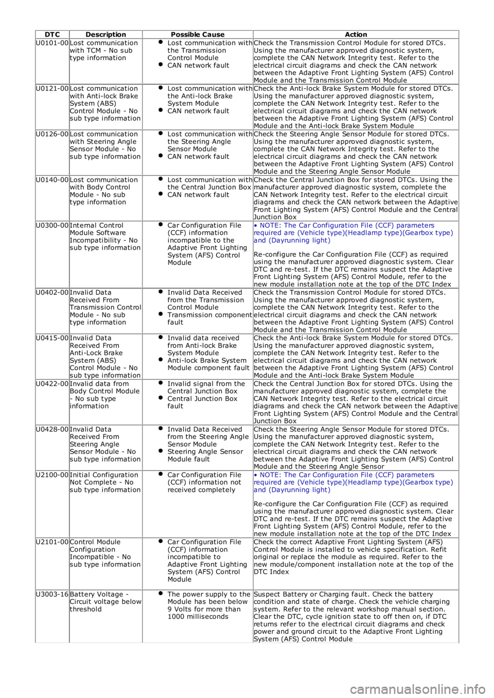
DT CDescriptionPossible CauseAction
U0101-00Lost communicat ionwit h TCM - No s ubt ype i nformati on
Los t communi cat ion wi tht he Trans mis s ionControl Modul eCAN net work fault
Check t he Trans mis s ion Cont rol Module for st ored DTCs .Us ing t he manufacturer approved diagnost ic sys tem,compl ete the CAN Net work Int egrit y t est . Refer t o theelectrical ci rcuit diagrams and check t he CAN networkbet ween t he Adapt ive Front Li ght ing Sys tem (AFS) ControlModul e and t he Trans mis s ion Cont rol Modul eU0121-00Lost communicat ionwit h Ant i-lock BrakeSyst em (ABS)Control Module - Nos ub type i nformati on
Los t communi cat ion wi tht he Anti -l ock BrakeSys tem Modul eCAN net work fault
Check t he Anti -l ock Brake Sys t em Module for s tored DTCs.Us ing t he manufacturer approved diagnost ic sys tem,compl ete the CAN Net work Int egrit y t est . Refer t o theelectrical ci rcuit diagrams and check t he CAN networkbet ween t he Adapt ive Front Li ght ing Sys tem (AFS) ControlModul e and t he Anti -l ock Brake Sys t em ModuleU0126-00Lost communicat ionwit h St eering Angl eSens or Module - Nos ub type i nformati on
Los t communi cat ion wi tht he Steering AngleSensor ModuleCAN net work fault
Check t he Steering Angle Sens or Modul e for s t ored DTCs .Us ing t he manufacturer approved diagnost ic sys tem,compl ete the CAN Net work Int egrit y t est . Refer t o theelectrical ci rcuit diagrams and check t he CAN networkbet ween t he Adapt ive Front Li ght ing Sys tem (AFS) ControlModul e and t he Steeri ng Angle Sens or Module
U0140-00Lost communicat ionwit h Body ControlModule - No subt ype i nformati on
Los t communi cat ion wi tht he Central Junct ion BoxCAN net work fault
Check t he Central Junct ion Box for s tored DTCs . Us ing themanufacturer approved diagnost ic sys tem, complet e t heCAN Net work Integri ty tes t. Refer t o t he electrical ci rcuitdiagrams and check the CAN network bet ween t he Adapt iveFront Lighti ng Sys t em (AFS) Cont rol Modul e and t he CentralJuncti on Box
U0300-00Int ernal Cont rolModule Soft wareIncompati bili ty - Nos ub type i nformati on
Car Configurat ion Fi le(CCF) i nformati oni ncompati ble t o t heAdapti ve Front Li ghti ngSys tem (AFS) Cont rolModule
• NOTE: The Car Configurat ion Fil e (CCF) parametersrequired are (Vehicle type)(Headl amp t ype)(Gearbox t ype)and (Dayrunning light )
Re-configure the Car Confi gurati on Fil e (CCF) as requi redusi ng t he manufact urer approved diagnost ic s ys tem. Cl earDTC and re-t es t . If t he DTC remains s us pect t he Adapt iveFront Lighti ng Sys t em (AFS) Cont rol Modul e, refer t o t henew module ins tall ati on not e at t he t op of the DTC IndexU0402-00Invali d Dat aRecei ved FromTrans mis s ion Cont rolModule - No subt ype i nformati on
Inval id Dat a Recei vedfrom the Transmis si onControl Modul eTrans mi ss i on componentfaul t
Check t he Trans mis s ion Cont rol Module for st ored DTCs .Us ing t he manufacturer approved diagnost ic sys tem,compl ete the CAN Net work Int egrit y t est . Refer t o theelectrical ci rcuit diagrams and check t he CAN networkbet ween t he Adapt ive Front Li ght ing Sys tem (AFS) ControlModul e and t he Trans mis s ion Cont rol Modul eU0415-00Invali d Dat aRecei ved FromAnti -Lock BrakeSyst em (ABS)Control Module - Nos ub type i nformati on
Inval id dat a receivedfrom Anti -l ock BrakeSys tem Modul eAnt i-lock Brake Syst emModule component fault
Check t he Anti -l ock Brake Sys t em Module for s tored DTCs.Us ing t he manufacturer approved diagnost ic sys tem,compl ete the CAN Net work Int egrit y t est . Refer t o theelectrical ci rcuit diagrams and check t he CAN networkbet ween t he Adapt ive Front Li ght ing Sys tem (AFS) ControlModul e and t he Anti -l ock Brake Sys t em Module
U0422-00Invali d data fromBody Cont rol Module- No s ub t ypeinformat ion
Inval id s i gnal from theCentral Juncti on BoxCentral Juncti on Boxfaul t
Check t he Central Junct ion Box for s tored DTCs . Us ing themanufacturer approved diagnost ic sys tem, complet e t heCAN Net work Integri ty tes t. Refer t o t he electrical ci rcuitdiagrams and check the CAN network bet ween t he Adapt iveFront Lighti ng Sys t em (AFS) Cont rol Modul e and t he CentralJuncti on Box
U0428-00Invali d Dat aRecei ved FromSteering AngleSens or Module - Nos ub type i nformati on
Inval id Dat a Recei vedfrom the St eeri ng Angl eSensor ModuleSt eering Angle Sens orModule fault
Check t he Steering Angle Sens or Modul e for s t ored DTCs .Us ing t he manufacturer approved diagnost ic sys tem,compl ete the CAN Net work Int egrit y t est . Refer t o theelectrical ci rcuit diagrams and check t he CAN networkbet ween t he Adapt ive Front Li ght ing Sys tem (AFS) ControlModul e and t he Steeri ng Angle Sens or
U2100-00Ini ti al Configurat ionNot Complet e - Nos ub type i nformati on
Car Configurat ion Fi le(CCF) i nformati on notreceived complet ely
• NOTE: The Car Configurat ion Fil e (CCF) parametersrequired are (Vehicle type)(Headl amp t ype)(Gearbox t ype)and (Dayrunning light )
Re-configure the Car Confi gurati on Fil e (CCF) as requi redusi ng t he manufact urer approved diagnost ic s ys tem. Cl earDTC and re-t es t . If t he DTC remains s us pect t he Adapt iveFront Lighti ng Sys t em (AFS) Cont rol Modul e, refer t o t henew module ins tall ati on not e at t he t op of the DTC IndexU2101-00Control ModuleConfigurat ionIncompati ble - Nos ub type i nformati on
Car Configurat ion Fi le(CCF) i nformati oni ncompati ble t oAdapti ve Front Li ghti ngSys tem (AFS) Cont rolModule
Check t he correct Adapti ve Front Li ght ing Sys t em (AFS)Cont rol Module is i ns t alled to vehicle s pecificati on. Refitori gi nal or repl ace the modul e as required. Refer to thenew module/component ins tall ati on note at t he t op of theDTC Index
U3003-16Batt ery Vol tage -Circui t vol tage belowt hreshol d
The power s upply to theModule has been below9 Vol ts for more than1000 mi ll is econds
Sus pect Bat t ery or Charging fault . Check t he batt erycondit ion and st ate of charge. Check t he vehicle chargi ngs ys t em. Refer to the relevant workshop manual s ect ion.Clear the DTC, cycl e i gni ti on s tat e to off t hen on, i f DTCret urns refer to the el ect ri cal circui t diagrams and checkpower and ground ci rcuit t o t he Adapt ive Front Light ingSys t em (AFS) Cont rol Modul e
Page 147 of 3229
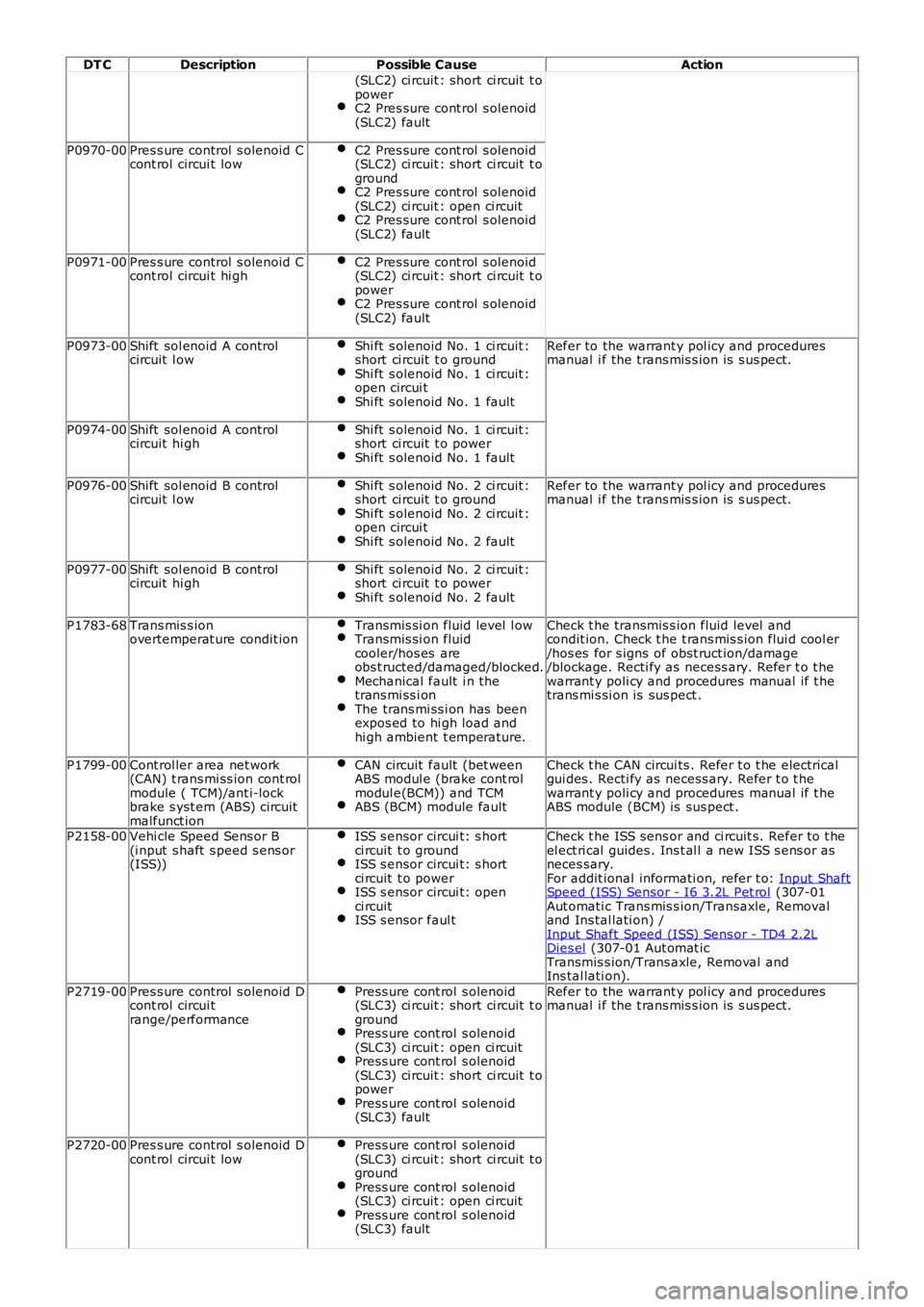
DT C
Description Possible Cause Action
(SLC2) ci rcuit : short ci rcuit t o
power
C2 Pres sure cont rol s olenoid
(SLC2) fault P0970-00
Pres s ure control s olenoid C
cont rol circui t low C2 Pres sure cont rol s olenoid
(SLC2) ci rcuit : short ci rcuit t o
ground C2 Pres sure cont rol s olenoid
(SLC2) ci rcuit : open ci rcuit C2 Pres sure cont rol s olenoid
(SLC2) fault P0971-00
Pres s ure control s olenoid C
cont rol circui t hi gh C2 Pres sure cont rol s olenoid
(SLC2) ci rcuit : short ci rcuit t o
power C2 Pres sure cont rol s olenoid
(SLC2) fault P0973-00
Shift sol enoid A control
circuit l ow Shi ft s olenoid No. 1 ci rcuit :
short ci rcuit t o ground Shi ft s olenoid No. 1 ci rcuit :
open circui t Shi ft s olenoid No. 1 fault Refer to the warrant y pol icy and procedures
manual i f the t rans mis s ion is s us pect.
P0974-00 Shift sol enoid A control
circuit hi gh Shi ft s olenoid No. 1 ci rcuit :
short ci rcuit t o power Shi ft s olenoid No. 1 fault
P0976-00
Shift sol enoid B control
circuit l ow Shi ft s olenoid No. 2 ci rcuit :
short ci rcuit t o ground Shi ft s olenoid No. 2 ci rcuit :
open circui t Shi ft s olenoid No. 2 fault Refer to the warrant y pol icy and procedures
manual i f the t rans mis s ion is s us pect.
P0977-00 Shift sol enoid B control
circuit hi gh Shi ft s olenoid No. 2 ci rcuit :
short ci rcuit t o power Shi ft s olenoid No. 2 fault
P1783-68
Trans mis s ion
overtemperat ure condit ion Transmis si on fluid level l ow Transmis si on fluid
cooler/hos es are
obs t ructed/damaged/blocked. Mechanical fault i n the
trans mi ss i on The trans mi ss i on has been
expos ed to hi gh load and
hi gh ambient t emperature. Check t he transmis s ion fluid level and
condit ion. Check t he t rans mis s ion flui d cool er
/hos es for s igns of obst ruct ion/damage
/blockage. Recti fy as necess ary. Refer t o t he
warrant y poli cy and procedures manual if t he
trans mi s si on is sus pect .
P1799-00 Cont rol ler area net work
(CAN) t rans mi ss ion cont rol
module ( TCM)/ant i-lock
brake s yst em (ABS) circuit
malfunct ion CAN circuit fault (bet ween
ABS modul e (brake cont rol
modul e(BCM)) and TCM ABS (BCM) module fault Check t he CAN circui ts . Refer t o t he electrical
gui des . Recti fy as necess ary. Refer t o t he
warrant y poli cy and procedures manual if t he
ABS module (BCM) is sus pect .
P2158-00 Vehi cle Speed Sens or B
(i nput s haft s peed s ens or
(ISS)) ISS s ensor circui t: s hort
ci rcuit t o ground ISS s ensor circui t: s hort
ci rcuit t o power ISS s ensor circui t: open
ci rcuit ISS s ensor faul t Check t he ISS sens or and ci rcuit s. Refer to t he
el ect ri cal guides . Ins t al l a new ISS s ens or as
neces sary.
For addit ional informati on, refer t o: Input Shaft Speed (ISS) Sensor - I6 3.2L Pet rol (307-01
Aut omati c Trans mis s ion/Transaxle, Removal
and Ins tal lati on) /
Input Shaft Speed (ISS) Sens or - TD4 2.2L Dies el (307-01 Aut omat ic
Transmis s ion/Trans axle, Removal and
Ins tal lati on).
P2719-00 Pres s ure control s olenoid D
cont rol circui t
range/performance Press ure cont rol s olenoid
(SLC3) ci rcuit : short ci rcuit t o
ground Press ure cont rol s olenoid
(SLC3) ci rcuit : open ci rcuit Press ure cont rol s olenoid
(SLC3) ci rcuit : short ci rcuit t o
power Press ure cont rol s olenoid
(SLC3) fault Refer to the warrant y pol icy and procedures
manual i f the t rans mis s ion is s us pect.
P2720-00 Pres s ure control s olenoid D
cont rol circui t low Press ure cont rol s olenoid
(SLC3) ci rcuit : short ci rcuit t o
ground Press ure cont rol s olenoid
(SLC3) ci rcuit : open ci rcuit Press ure cont rol s olenoid
(SLC3) fault
Page 180 of 3229
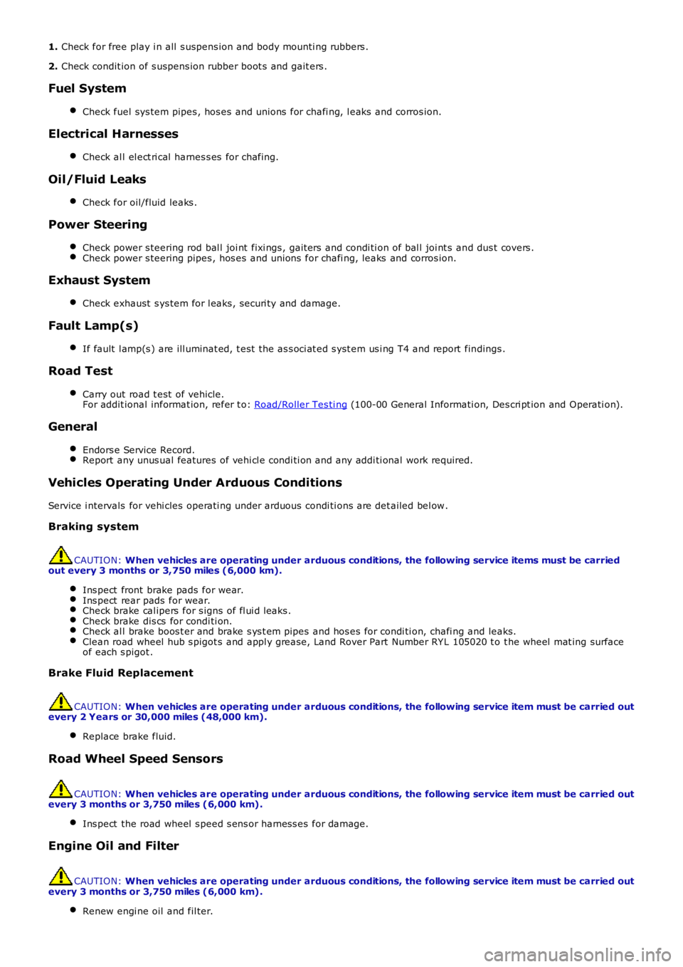
1. Check for free play i n all s uspens ion and body mounti ng rubbers .
2. Check condit ion of s uspens ion rubber boot s and gait ers .
Fuel System
Check fuel sys tem pipes , hos es and unions for chafi ng, l eaks and corros ion.
Electrical Harnesses
Check al l el ect ri cal harnes s es for chafing.
Oil/Fluid Leaks
Check for oil/fluid leaks .
Power Steering
Check power s teering rod bal l joi nt fixi ngs , gait ers and condi ti on of bal l joi nt s and dus t covers .Check power s teering pipes , hos es and unions for chafi ng, leaks and corros ion.
Exhaust System
Check exhaust s ys tem for l eaks , securi ty and damage.
Fault Lamp(s)
If fault l amp(s ) are ill uminat ed, t est the as s oci at ed s yst em us i ng T4 and report findings .
Road Test
Carry out road t est of vehicle.For addit ional informat ion, refer t o: Road/Roller Tes ti ng (100-00 General Informati on, Des cri pt ion and Operati on).
General
Endors e Service Record.Report any unus ual features of vehi cl e condi ti on and any addi ti onal work required.
Vehicles Operating Under Arduous Conditions
Service i ntervals for vehi cles operati ng under arduous condi ti ons are det ailed bel ow.
Braking system
CAUTION: When vehicles are operating under arduous conditions, the following service items must be carriedout every 3 months or 3,750 miles (6,000 km).
Ins pect front brake pads for wear.Ins pect rear pads for wear.Check brake cal ipers for s igns of fl ui d l eaks .Check brake dis cs for condi ti on.Check al l brake boos t er and brake s ys t em pipes and hos es for condi ti on, chafi ng and leaks.Clean road wheel hub s pigot s and appl y greas e, Land Rover Part Number RY L 105020 t o t he wheel mat ing surfaceof each s pigot .
Brake Fluid Replacement
CAUTION: When vehicles are operating under arduous conditions, the following service item must be carried outevery 2 Years or 30,000 miles (48,000 km).
Replace brake fluid.
Road Wheel Speed Sensors
CAUTION: When vehicles are operating under arduous conditions, the following service item must be carried outevery 3 months or 3,750 miles (6,000 km).
Ins pect the road wheel s peed s ens or harness es for damage.
Engine Oil and Filter
CAUTION: When vehicles are operating under arduous conditions, the following service item must be carried outevery 3 months or 3,750 miles (6,000 km).
Renew engi ne oil and fil ter.
Page 192 of 3229
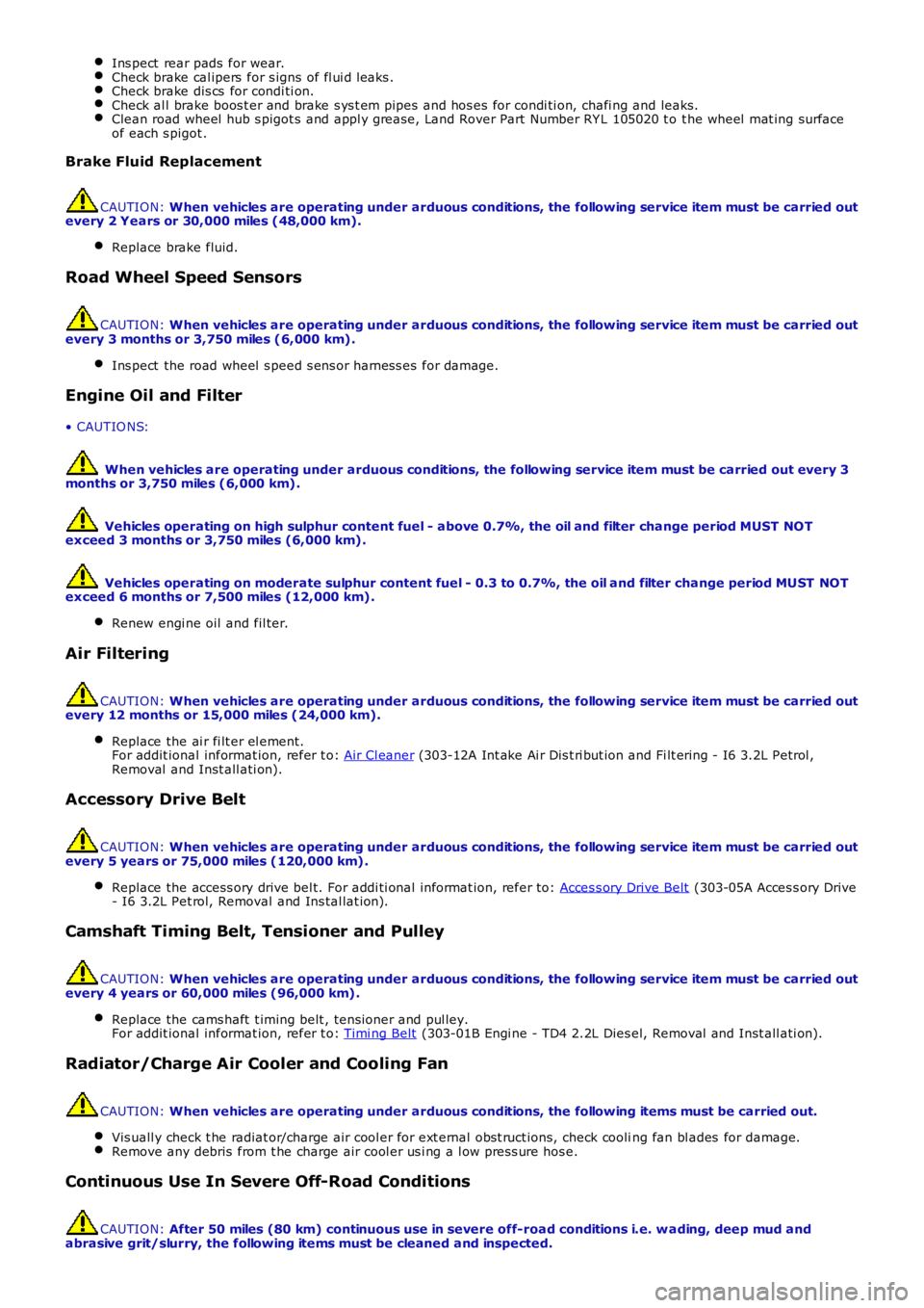
Ins pect rear pads for wear.
Check brake cal ipers for s igns of fl ui d l eaks .
Check brake dis cs for condi ti on.
Check al l brake boos t er and brake s ys t em pipes and hos es for condi ti on, chafi ng and
leaks.Clean road wheel hub s pigot s and appl y greas e, Land Rover Part Number RY L 105020 t o
t he wheel mat ing surface
of each s pigot . Brake Fluid Replacement
CAUTION:
When vehicles are operating under arduous conditions, the following service item mus t be carried out
every 2 Years or 30,000 miles (48,000 km).
Replace brake fluid. Road Wheel Speed Sensors
CAUTION:
When vehicles are operating under arduous conditions, the following service item mus t be carried out
every 3 months or 3,750 miles (6,000 km).
Ins pect the road wheel s peed s ens or harness es for damage. Engine Oil and Filter
• CAUTIO NS:
When vehicles are operating under arduous conditions, the following service item mus t be carried out every 3
months or 3,750 miles (6,000 km).
Vehicles operating on high sulphur content fuel - above 0.7%, the oil and filter cha nge period MUST NOT
exceed 3 months or 3,750 miles (6,000 km).
Vehicles operating on moderate sulphur content fuel - 0.3 to 0.7%, the oil and filte r change period MUST NOT
exceed 6 months or 7,500 miles (12,000 km).
Renew engi ne oil and fil ter. Air Filtering
CAUTION:
When vehicles are operating under arduous conditions, the following service item mus t be carried out
every 12 months or 15,000 miles (24,000 km).
Replace the ai r fi lt er el ement.
For addit ional informat ion, refer t o: Air Cl eaner (303-12A Int ake Ai r Dis t ri but ion and Fi lt ering - I6 3.2L Petrol ,
Removal and Inst all ati on). Accessory Drive Belt
CAUTION:
When vehicles are operating under arduous conditions, the following service item mus t be carried out
every 5 years or 75,000 miles (120,000 km).
Replace the access ory drive bel t. For addi ti onal informat ion, refer to: Acces s ory Drive Belt (303-05A Acces s ory Drive
- I6 3.2L Pet rol, Removal and Ins tal lat ion). Camshaft Timing Belt, Tensioner and Pulley
CAUTION:
When vehicles are operating under arduous conditions, the following service item mus t be carried out
every 4 years or 60,000 miles (96,000 km).
Replace the cams haft t iming belt , tens ioner and pul ley.
For addit ional informat ion, refer t o: Timi ng Belt (303-01B Engi ne - TD4 2.2L Dies el, Removal and Inst all ati on).
Radiator/Charge Air Cooler and Cooling Fan
CAUTION:
When vehicles are operating under arduous conditions, the following items must be ca rried out.
Vis uall y check t he radiat or/charge air cool er for ext ernal obst ruct ions, check cooli ng fan bl ades for damage.Remove any debris from t he charge air cool er us i ng a l ow pres s ure hos e.
Continuous Use In Severe Off-Road Conditions
CAUTION:
After 50 miles (80 km) continuous use in severe off-road conditions i.e. w ading, dee p mud and
abrasive grit/slurry, the following items must be cleaned and inspected.
Page 498 of 3229
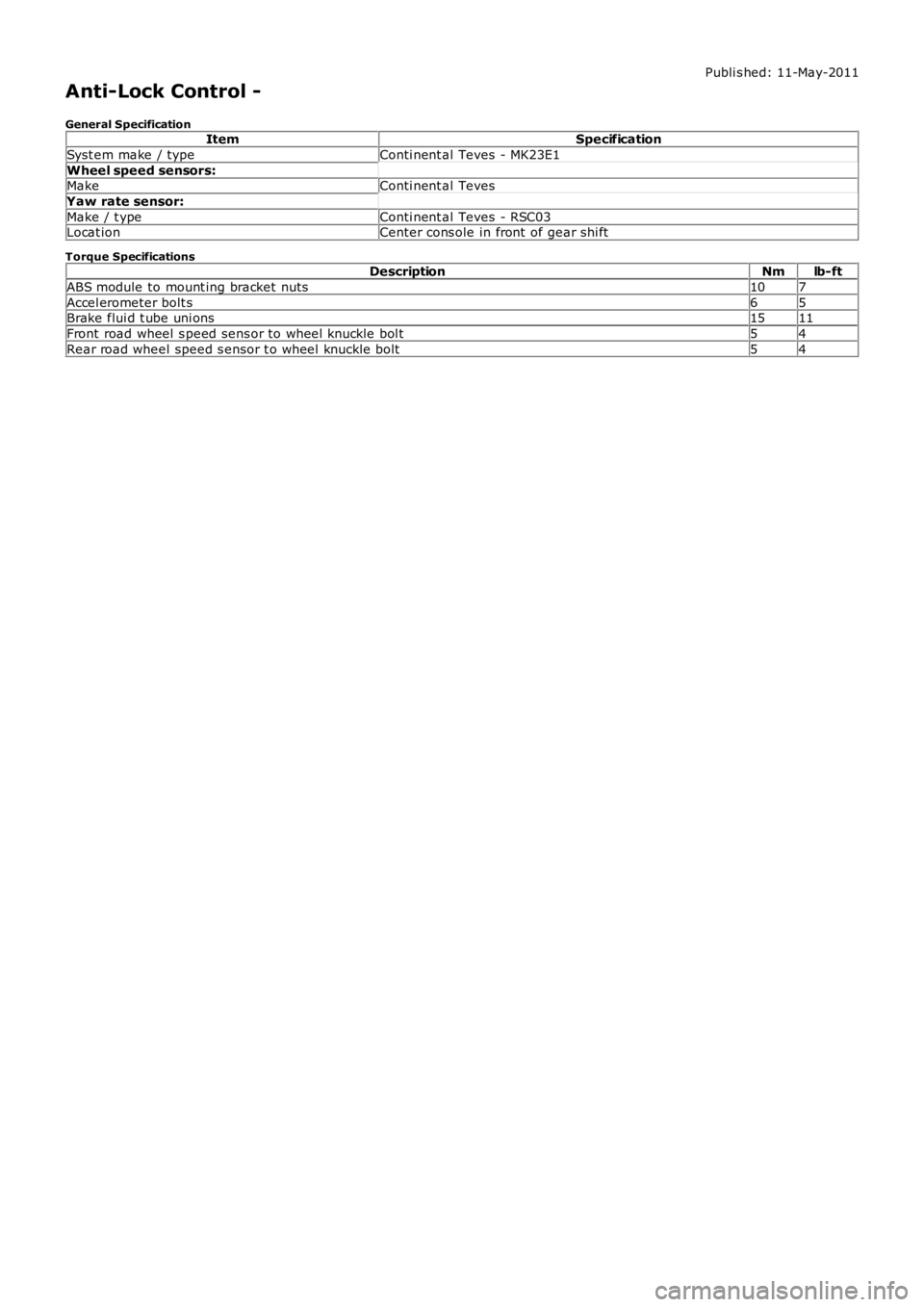
Publi s hed: 11-May-2011
Anti-Lock Control -
General SpecificationItemSpecification
Syst em make / typeConti nent al Teves - MK23E1
Wheel speed sensors:MakeConti nent al Teves
Yaw rate sensor:
Make / t ypeConti nent al Teves - RSC03Locat ionCenter cons ole in front of gear shi ft
Torque SpecificationsDescriptionNmlb-ft
ABS module to mount ing bracket nuts107
Accel erometer bolt s65Brake flui d t ube uni ons1511
Front road wheel s peed sens or to wheel knuckle bol t54
Rear road wheel speed s ensor t o wheel knuckle bolt54
Page 511 of 3229
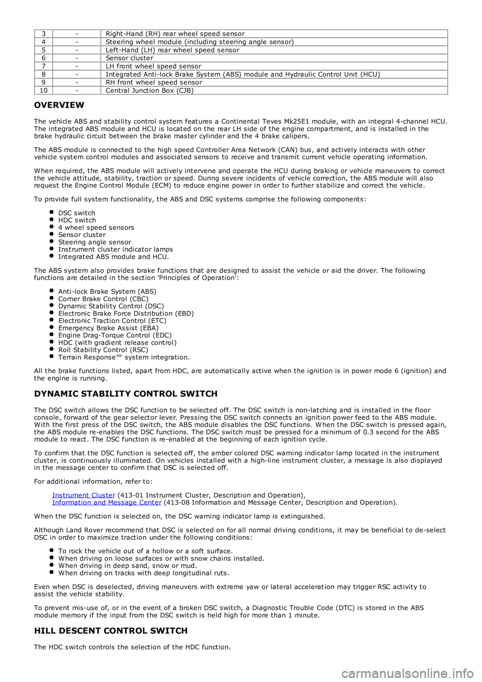
3-Right -Hand (RH) rear wheel s peed s ens or
4-Steering wheel modul e (including s t eering angle sens or)
5-Left -Hand (LH) rear wheel s peed s ens or6-Sensor clus ter
7-LH front wheel speed s ensor
8-Int egrat ed Anti -l ock Brake Sys t em (ABS) modul e and Hydrauli c Cont rol Unit (HCU)9-RH front wheel speed s ensor
10-Central Junct ion Box (CJB)
OVERVIEW
The vehi cl e ABS and s t abi li ty control sys tem feat ures a Cont inental Teves Mk25E1 module, wi th an int egral 4-channel HCU.The int egrated ABS modul e and HCU is l ocat ed on t he rear LH s ide of t he engine compart ment, and i s ins tal led i n t hebrake hydrauli c ci rcuit bet ween the brake mas ter cyl inder and the 4 brake calipers.
The ABS module is connect ed to the hi gh s peed Cont roll er Area Net work (CAN) bus , and acti vel y int eracts wi th othervehi cl e s yst em cont rol modules and as sociat ed s ens ors to recei ve and transmit current vehicle operat ing informati on.
W hen requi red, t he ABS module wi ll acti vel y int ervene and operate the HCU during braki ng or vehi cl e maneuvers t o correctt he vehi cl e att it ude, s t abi li ty, t racti on or speed. During severe incident s of vehicle correct ion, t he ABS module will al soreques t the Engine Cont rol Modul e (ECM) to reduce engi ne power i n order t o further stabil ize and correct t he vehicle.
To provide full s ys tem functi onali ty, t he ABS and DSC s ys tems compris e t he fol lowing component s :
DSC s wit chHDC s wi tch4 wheel s peed s ens orsSens or clus terSteering angle s ens orIns t rument clus ter i ndi cat or lampsInt egrat ed ABS module and HCU.
The ABS s yst em al s o provides brake funct ions t hat are des igned to ass is t t he vehi cle or aid the driver. The followi ngfuncti ons are det ai led i n t he s ect ion 'Principl es of Operati on':
Anti -l ock Brake Sys t em (ABS)Corner Brake Control (CBC)Dynamic St abi li ty Cont rol (DSC)Electroni c Brake Force Di s tributi on (EBD)Electroni c Tracti on Control (ETC)Emergency Brake As s is t (EBA)Engi ne Drag-Torque Control (EDC)HDC (wit h gradi ent releas e cont rol )Roll Stabi lit y Control (RSC)Terrai n Res pons e™ sys tem int egrati on.
All t he brake funct ions li s ted, apart from HDC, are automat icall y act ive when t he i gni ti on is in power mode 6 (igni ti on) andt he engi ne is runni ng.
DYNAMIC STABILITY CONTROL SWITCH
The DSC s wit ch all ows the DSC functi on to be s elect ed off. The DSC s wi tch i s non-latchi ng and is i nst all ed in the floorcons ole, forward of the gear s el ect or lever. Pres s ing t he DSC s wi tch connects an ignit ion power feed to t he ABS modul e.W i th the firs t pres s of the DSC swit ch, t he ABS module di sabl es the DSC funct ions . When t he DSC s wi tch i s pres sed agai n,t he ABS module re-enables t he DSC funct ions. The DSC swi tch must be press ed for a minimum of 0.3 s econd for the ABSmodule t o react . The DSC functi on is re-enabled at t he beginning of each ignit ion cycle.
To confirm that t he DSC functi on is sel ect ed off, the amber colored DSC warni ng indicator l amp located i n t he ins t rumentclus ter, is conti nuous ly i ll uminated. On vehicles i nst all ed wit h a hi gh-li ne ins t rument clus ter, a mes sage i s als o di spl ayedin the mess age cent er to confirm t hat DSC is s elect ed off.
For addit ional informat ion, refer t o:
Ins trument Clus ter (413-01 Ins t rument Clus t er, Descripti on and Operat ion),Informat ion and Mes s age Cent er (413-08 Informati on and Mes sage Cent er, Descripti on and Operat ion).
W hen t he DSC funct ion i s s elected on, t he DSC warni ng indicator l amp is ext inguis hed.
Alt hough Land Rover recommend t hat DSC is s elected on for all normal driving condit ions, i t may be benefi ci al t o de-sel ectDSC i n order t o maximi ze tract ion under t he foll owing condit ions:
To rock t he vehicle out of a holl ow or a s oft surface.W hen driving on loose s urfaces or wit h s now chains ins t al led.W hen driving i n deep s and, s now or mud.W hen driving on tracks wi th deep l ongi tudinal rut s .
Even when DSC is des elected, dri ving maneuvers wi th ext reme yaw or lateral acceleration may trigger RSC act ivit y t oas si st the vehicle st abili ty.
To prevent mis -use of, or in the event of a broken DSC s wit ch, a Diagnost ic Troubl e Code (DTC) i s s tored in the ABSmodule memory i f the input from t he DSC s wit ch is hel d high for more than 1 minut e.
HILL DESCENT CONTROL SWITCH
The HDC s wi tch control s t he s el ect ion of t he HDC funct ion.