2006 LAND ROVER FRELANDER 2 turn signal bulb
[x] Cancel search: turn signal bulbPage 1771 of 3229

Vehicle i n power mode 6 (all vehi cles except NAS vehicles )Vehicle i n power mode 6 for 75 s econds (NAS vehicl es onl y)Vehicle s peed is greater t han 6 mph (10 kph)Dri vers s afet y belt not s ecured in i ts buckleLarge pas senger det ect ed i n front pas s enger s eat wit h an uns ecured safety bel t.
The warni ng indicator wi ll flas h at a frequency of 2 Hz while accompani ed by a chime from the i nst rument clus ter for 10s econds. Thi s is foll owed by a 10 s econd period where the warning i ndicat or is permanent ly ill uminat ed and the s ounder i ss il ent . Thi s 10 s econd cycle wi ll be repeat ed for a maxi mum of 190 seconds or any of t he condit ions l is t ed above cease toexis t.
Supplemental Restraint System Warning Indicator
The Suppl ement al Rest rai nt Sys tem (SRS) warning i ndi cat or is i lluminated on recei pt of a medium s peed CAN bus si gnalfrom the CJB. The si gnal originat es in t he RCM whi ch monit ors t he condi ti on of the SRS and ill uminat es the red warni ngindicat or accordingly.
The SRS warni ng indicator i s il lumi nat ed by t he RCM for a 6 s econd bul b check when the vehicle firs t ent ers power mode 6.If a fault is detect ed wit h t he indicator, the ins trument cl us t er returns a medi um speed CAN bus s ignal vi a t he CJB to theRCM and a Diagnos t ic Troubl e Code (DTC) i s s tored in the RCM's memory. The mes s age 'SrS' wi ll als o be di spl ayed i n t heodometer.For addit ional informat ion, refer t o: Informat ion and Mes s age Cent er (413-08 Informat ion and Mes s age Cent er, Des cript ionand Operat ion).
Left and Right Hand Turn Signal Indicators
The green l eft and right hand turn s ignal i ndicat ors are i ll uminated on recei pt of medium speed CAN bus s i gnals from t heCJB. The CJB provi des a CAN bus s ignal wit h one of t he foll owing values :
0 - LH st eeri ng col umn mul ti -funct ion s wit ch in the central pos it ion1 - LH st eeri ng col umn mul ti -funct ion s wit ch in the LH turn posi ti on2 - LH st eeri ng col umn mul ti -funct ion s wit ch in the RH turn pos it ion3 - Hazard fl as hers reques t ed.
If the vehicle is i n power mode 6 t he ins trument cl ust er wil l fl as h the appropri ate turn s ignal i ndicat or if a medium speedCAN bus s ignal is recei ved wit h a value of 1 or 2. Medi um s peed CAN bus s ignals wi th a value of 3 wi ll acti vat e both theLH and RH turn s ignal i ndicat ors si mult aneous ly i rrespecti ve of power mode.
W hen acti vat ed, the l eft and right hand turn s ignal indicators wil l be accompanied by 'ti ck t ock' chimes from t he ins trumentclus ter s ounder.
Brake Warning Indicator
EBA and EBD warnings are trans mi tt ed t o t he CJB from t he ABS module over t he high s peed CAN bus . Thes e s ignals arerel ayed t o t he i ns t rument clus ter on t he medium s peed CAN bus and wil l act ivate the brake warning i ndicat or when t hevehi cl e i s in power mode 6. If an EBA warni ng is request ed, the i ndi cat or wil l ill uminat e in an amber color. If an EBDwarni ng is reques t ed, t he indi cat or will i ll uminate in a red color.
Low brake flui d level warnings are als o t rans mit t ed to the i nst rument clus t er from the CJB on the medi um s peed CAN bus .The s ignal origi nat es in the ABS modul e which recei ves a hardwired input from the brake flui d level s ens or. If a l ow brakefl uid warning i s reques ted, the indicator wil l il lumi nat e i n a red col or when the vehicle is i n power mode 6.
The brake warni ng indi cat or i s als o s ubject t o a 3 second bul b check when the vehicle firs t ent ers power mode 6. Theindicat or wi ll i lluminate in a amber color for 1.5 s econds t hen a red col or for 1.5 s econds .
High Eng ine Coolant Temperature Warning Ind icator
The red hi gh Engine Coolant Temperature (ECT) warning i ndi cat or is control led by the engine t emperat ure gage s oft ware(see above).
Headlamp High Beam Indicator
The blue headlamp hi gh beam i ndi cat or is i ll uminated on recei pt of a medium s peed CAN bus si gnal from the CJB. Thes ignal origi nat es in the l ight s wit ch module and i s t ransmit ted t o t he CJB over t he LIN bus. The i nst rument clus t er will onlyil lumi nat e t he headl amp high beam indicator when t he vehicle i s in power mode 6 and t he LH s teeri ng column mul ti -functi on s wit ch is moved t o t he high beam pos i ti on.
Tire Pressure Monitoring System Indicator
The Tire Pres s ure Moni tori ng Syst em (TPMS) indicator i s cont rol led by t he ins t rument clus ter on receipt of medium s peedCAN bus s ignals from t he CJB. The s ignal ori gi nates i n t he TPMS module. The indicator i s il lumi nat ed in an amber col or fora 3 second bulb check by the TPMS modul e when t he vehi cl e enters power mode 6. If t he indicator remains i lluminated orfl ashes after t he engi ne is st art ed or when dri vi ng, the TPMS has developed a faul t. The t ire pres s ures s houl d bemonit ored manuall y unti l the fault is recti fi ed.For addit ional informat ion, refer t o: W heels and Ti res (204-04 W heels and Tires , Des cript ion and Operat ion).
Anti-lock Brake System Warning Indicator
The Anti -l ock Brake Sys t em (ABS) warning i ndicat or is controll ed by the ABS module whi ch trans mi ts a high s peed CAN busmes s age to t he CJB. The CJB relays t he mes sage t o t he i ns t rument clus ter over the medi um s peed CAN bus . The warningindicat or i s il lumi nat ed i n an amber col or for 3 s econds for a bulb check by the ABS modul e when t he vehi cl e enters powermode 6. If the warning i ndi cat or remains ill uminat ed or ill uminat es when drivi ng, an ABS fault has occurred and t he ABSfuncti on wil l not be avai lable.
Duri ng the bul b check, if t he warni ng indicator comes on for 0.5 s econd, t hen goes off for 0.5 second and is then
Page 1929 of 3229

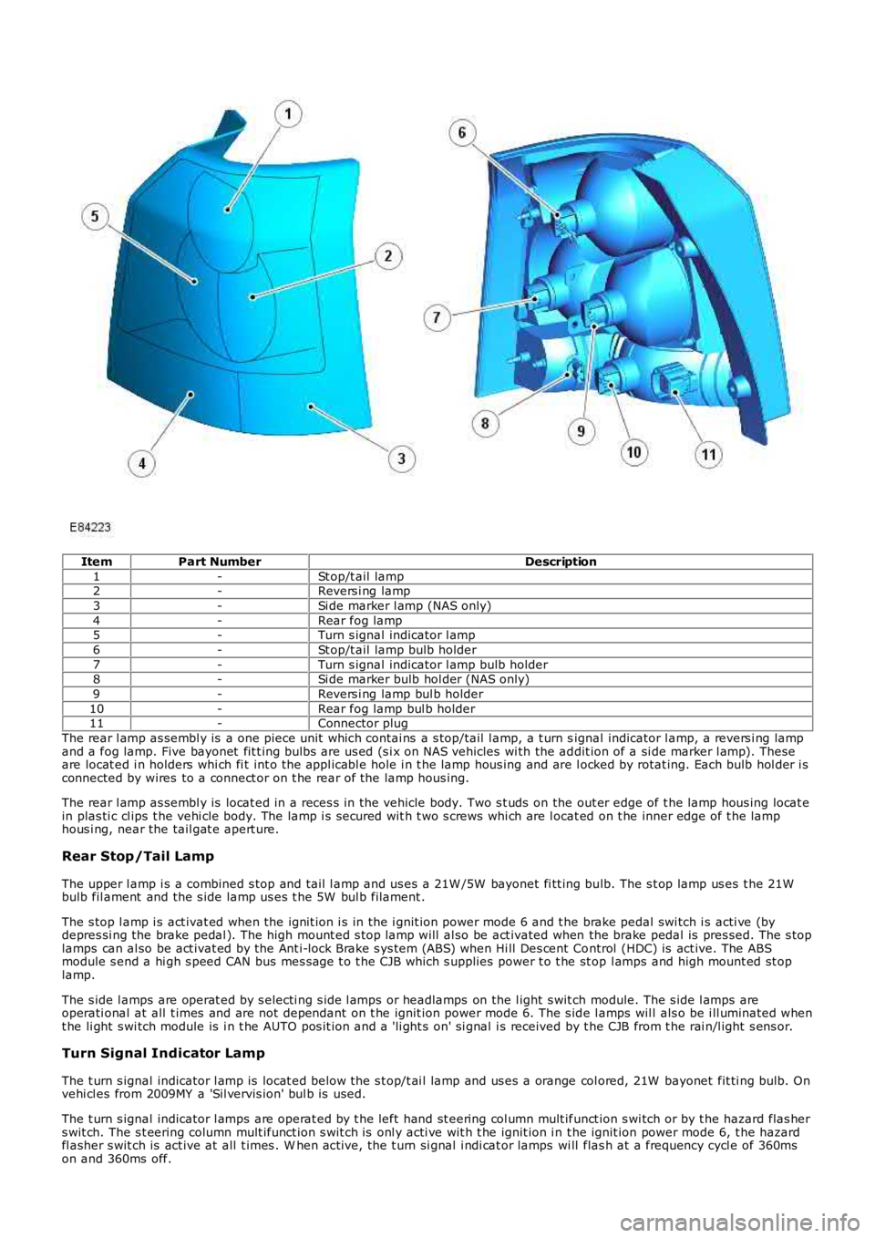
ItemPart NumberDescription
1-St op/t ail lamp2-Revers i ng lamp
3-Si de marker l amp (NAS only)
4-Rear fog lamp5-Turn s ignal indicator l amp
6-St op/t ail lamp bulb holder
7-Turn s ignal indicator l amp bulb holder8-Si de marker bulb hol der (NAS only)
9-Revers i ng lamp bul b holder
10-Rear fog lamp bul b holder11-Connector plug
The rear l amp as sembl y is a one piece unit which contai ns a s top/tail l amp, a t urn signal indicator l amp, a revers i ng lampand a fog lamp. Five bayonet fit t ing bulbs are us ed (s i x on NAS vehicles wi th the addit ion of a si de marker l amp). Theseare locat ed i n holders whi ch fi t int o the appl icabl e hole i n t he lamp hous ing and are l ocked by rotat ing. Each bulb hol der i sconnected by wires to a connect or on t he rear of the lamp hous ing.
The rear l amp as sembl y is locat ed in a reces s in the vehicle body. Two s t uds on the out er edge of t he lamp hous ing locat ein plas ti c cl ips t he vehi cle body. The lamp i s s ecured wit h t wo s crews whi ch are l ocat ed on t he inner edge of t he lamphous i ng, near the tail gat e apert ure.
Rear Stop/Tail Lamp
The upper l amp i s a combined s top and tail l amp and us es a 21W /5W bayonet fi tt ing bulb. The s t op lamp us es t he 21Wbulb fil ament and the s ide lamp us es t he 5W bul b filament .
The s top l amp i s act ivat ed when the ignit ion i s in the i gnit ion power mode 6 and t he brake pedal swi tch i s acti ve (bydepres si ng the brake pedal ). The high mount ed s top lamp will al so be act ivated when the brake pedal is pres sed. The s toplamps can al so be act ivat ed by the Ant i-lock Brake s ys tem (ABS) when Hi ll Des cent Control (HDC) is act ive. The ABSmodule s end a hi gh s peed CAN bus mes sage t o t he CJB which s upplies power t o t he st op l amps and high mount ed st oplamp.
The s ide l amps are operat ed by s electi ng s ide l amps or headlamps on the l ight s wit ch module. The s ide l amps areoperati onal at all t imes and are not dependant on t he ignit ion power mode 6. The s ide l amps wil l als o be i ll uminated whent he li ght s wi tch module is i n t he AUTO pos it ion and a 'li ght s on' si gnal i s received by t he CJB from t he rai n/l ight s ens or.
Turn Signal Indicator Lamp
The t urn s ignal indicator l amp is locat ed below the s t op/t ai l lamp and us es a orange col ored, 21W bayonet fit ti ng bulb. Onvehi cl es from 2009MY a 'Sil vervis ion' bul b is used.
The t urn s ignal indicator l amps are operat ed by t he left hand st eering col umn mult ifunct ion s wi tch or by t he hazard flas hers wit ch. The s t eering column mult ifunct ion s wit ch is onl y acti ve wit h t he ignit ion i n t he ignit ion power mode 6, t he hazardfl asher s wit ch is act ive at all t imes . W hen act ive, the t urn si gnal i ndi cat or lamps wi ll flas h at a frequency cycl e of 360mson and 360ms off.
Page 1930 of 3229

If a bulb fails , t he remai ning t urn s i gnal indi cat or l amp bulb on that s ide of t he vehicle flas hes at normal s peed. Theappl icable t urn si gnal i ndi cat or in t he i ns t rument clus ter wi ll fl ash at double s peed t o al ert t he driver t o t he bul b fai lure.
Reversing Lamp
The revers i ng lamp is l ocat ed adjacent t o t he turn s ignal lamp and us es a 21W bayonet fit ti ng bul b.
The revers i ng lamp is acti ve when the ignit ion i s in the i gnit ion power mode 6 and the CJB receives a revers e s el ect eds ignal on the medi um s peed Control ler Area Network (CAN) bus . The aut omati c t rans miss ion has a revers e s wit ch whichs ens es when reverse is s elect ed.
Rear Fog Lamp
The rear fog lamp is l ocat ed at the bot tom of the rear lamp and us es a 21W bayonet fit ti ng bul b.
The rear fog lamp is controlled by the l ight cont rol module. W hen the i gni ti on s wit ch is i n t he ignit ion power mode 6 andt he li ght control modul e is in t he s ide l amp or headl amp pos it ion, the rear fog l amp s wit ch on t he li ght control modul e canbe pres s ed t o act ivat e the rear fog l amps . A rear fog lamp warning i ndicat or is ill uminat ed in t he i ns t rument clus ter whent he rear fog lamps are act ive.
Side Marker Lamp (NAS only)
The s ide marker l amp i s located i n t he outer part of t he rear lamp, adjacent to rear fog lamp and us es a W 5W wedgefi tt ing bul b.
The s ide marker l amp bulb, whi ch is fit ted i n a hol der l ocat es in an aperture in the rear lamp hous ing and i s rot ated t o l ockin pos i ti on. The s ide marker lamp is acti ve at all ti mes when t he s ide l amps are select ed on us ing t he li ght controlmodule. The s ide marker l amps wi ll als o be i ll uminated when the l ight cont rol module rot ary s wit ch is in t he 'AUTO'posi ti on and a 'light s on' s i gnal is received by t he CJB from t he li ght sens or.
HAZARD FLASHERS
The hazard flas hers are cont roll ed by a non-l atching s wi tch i n the cent re of t he inst rument panel . The hazard fl as hersoperate at al l ti mes when s elected and are not dependant on the ignit ion power mode.
W hen t he hazard flas hers are s el ect ed on, all of the front , rear and s ide t urn s i gnal indi cat or l amps operate as previous lydescribed and both left and right t urn s ignal indicators in the ins trument cl us t er al s o fl ash. The hazard warning flas hersfl ash at a rat e of 360ms on and 360ms off. W hen the hazard flas hers are act ive, t hey override any reques t for t urn si gnallamp operati on.
If a trail er i s fit ted, the trailer t urn s i gnal lamps wil l flas h at t he s ame frequency as t he vehi cle i ndi cat ors . The t rail erwarni ng indicator i n t he ins trument cl ust er wil l al s o fl ash. If a t rail er bul b i s defect ive, t he trail er warning i ndi cat or wil l notfl ash.
The hazard flas hers can als o be acti vat ed by a crash si gnal from the Res t raint s Control modul e (RCM). This i s received byt he CJB which act ivat es the hazard flas hers . The hazard flas hers can be cancell ed by changing t he i gni ti on power mode tot he auxi liary power mode 4 or t he off power mode 0 or t he cras h mode i s cancelled by the res trai nts control modul e.
LICENSE PLATE LAMPS
Two l icens e pl ate l amps are fi tt ed in the t ail gat e handle, above t he l icens e pl ate in t he upper t ail gat e. Each l amp us es a5W caples s t ype bul b.
The lamps are s ecured in the upper li ft gat e handle wi th int egral cl ips . The lamps can be released from t he handl e us ing as mall , fl at bl ade screwdriver. The l icense pl ate lamps are act ive at al l ti mes when t he si de lamps or headlamps ares wit ched on.
HIGH MOUNTED STOP LAMP
The high mount ed s top l amp i s located i n t he li ft gat e. Acces s t o the lamp i s by removal of t he upper li ft gate interior t rimpanel . Aft er releas ing t he lamp ret aining cl ips , the l amp can be removed from outs ide the vehicle.
The lamp compris es a pl ast ic hous ing wi th a red col ored l ens . The lamp is i ll uminated by a s ingle 16W caples s type bulb.
The high mount ed s top l amp i s act ivat ed, along wit h the tail l amp s t op lamps , when the ignit ion i s in ignit ion power mode6 and t he brake pedal swi tch i s acti ve (by pres s ing the brake pedal).
The high mount ed s top l amp and t he s top l amps can als o be acti vat ed by t he ABS when Hi ll Des cent Control (HDC) isact ive. A s i gnal on t he high s peed CAN bus from the ABS modul e i s pass ed t o t he CJB which s uppl ies power to the st oplamps .
SIDE TURN SIGNAL LAMPS
The s ide t urn si gnal l amps are l ocat ed in the front fender air vents . On vehicles from 2009MY , t he s ide t urn si gnal l ampshave cl ear l enses and orange colored bulbs . The lamps are clipped i nt o an aperture in the vent panel and can be removedby s li di ng rearwards and releasi ng t he front edge of t he lamp from t he vent .
The s ide t urn si gnal l amps use a 5W caples s bulb which is locat ed i n a holder. The lamps have the same functi onal it y ast he front and rear turn s ignal i ndicat or lamps and are operat ed by the left hand s t eering column mult ifunct ion s wit ch or byt he hazard fl asher s wit ch. The s t eering column mult ifunct ion s wit ch is onl y acti ve wit h t he ignit ion i n t he ignit ion powermode 6, t he hazard fl asher s wit ch is act ive at all t imes , regardl ess of t he power mode. W hen act ive, t he s ide t urn s i gnallamps will flas h at a frequency cycle of 360ms on and 360ms off. If a s ide t urn si gnal l amp bulb fail s, t he t urn s i gnalindicat or l amps cont inue t o flas h at t he normal rat e.
Page 2781 of 3229

61
Supplementary restraints system
R
Airbag deployment effectsAIRBAG WARNING LAMP
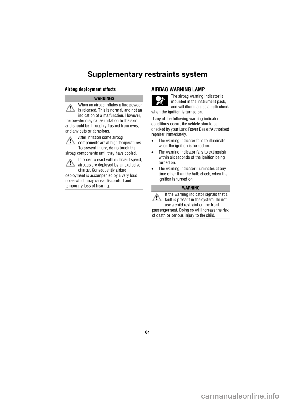
The airbag warning indicator is
mounted in the instrument pack,
and will illuminate as a bulb check
when the ignition is turned on.
If any of the following warning indicator
conditions occur, the vehicle should be
checked by your Land Ro ver Dealer/Authorised
repairer immediately.
• The warning indicator fails to illuminate
when the ignition is turned on.
• The warning indicator fails to extinguish
within six seconds of the ignition being
turned on.
• The warning indicator illuminates at any
time other than the bulb check, when the
ignition is turned on.WARNINGS
When an airbag inflates a fine powder
is released. This is normal, and not an
indication of a malf unction. However,
the powder may cause irritation to the skin,
and should be throughly flushed from eyes,
and any cuts or abrasions.
After inflation some airbag
components are at high temperatures.
To prevent injury, do no touch the
airbag components until they have cooled.
In order to react with sufficient speed,
airbags are deployed by an explosive
charge. Consequently airbag
deployment is accompan ied by a very loud
noise which may cause discomfort and
temporary loss of hearing.
WARNING
If the warning indicator signals that a
fault is present in the system, do not
use a child restraint on the front
passenger seat. Doing so will increase the risk
of death or serious injury to the child.