2006 LAND ROVER FRELANDER 2 hood release
[x] Cancel search: hood releasePage 218 of 3229
Stage 1:
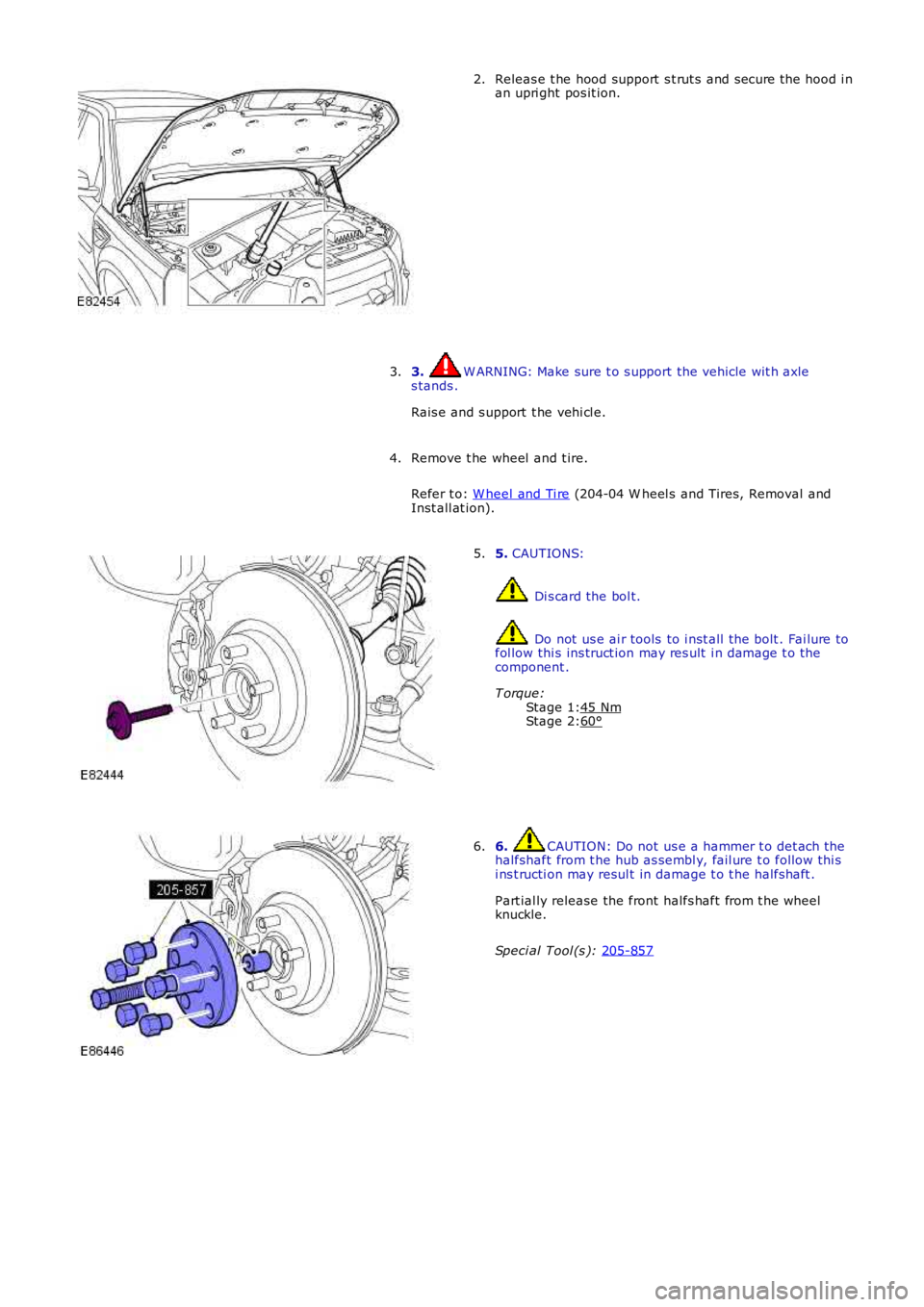
Stage 2: Releas e t he hood support s t rut s and s ecure the hood i n
an upri ght pos it ion.
2.
3. W ARNING: Make sure t o s upport the vehicle wit h axle
s tands .
Rais e and s upport t he vehi cl e.
3.
Remove t he wheel and t ire.
Refer t o: W heel and Ti re (204-04 W heel s and Tires, Removal and
Inst all at ion).
4. 5.
CAUTIONS: Di s card the bol t.
Do not us e ai r tools to i nst all t he bolt . Fai lure to
fol low thi s ins truct ion may res ult i n damage t o the
component .
T orque: 45 Nm 60°5.
6. CAUTION: Do not us e a hammer t o det ach t he
halfshaft from t he hub as sembl y, fail ure t o follow thi s
i ns t ructi on may resul t in damage t o t he halfshaft .
Part ial ly release the front halfs haft from t he wheel
knuckle.
Speci al Tool (s ): 205-857 6.
Page 949 of 3229
1
1
Is t he coolant expans ion t ank pres sure cap operati ng correctl y?
Yes GO t o B3 .
No INSTALL a new coolant expans ion t ank pres s ure cap. TEST t he s yst em for correct opera ti on.
B3: CHECK T HERMOST AT Check t he t hermos tat for correct operat ion. REFER to the t hermos t at component t es t i n t his
sect ion.
Is t he t hermos tat operat ing correct ly?
Yes
Check for correct operat ion of cooli ng fans , ci rcuit s , sens ors , modules , et c.
REFER t o: Electroni c Engine Controls (303-14B Electronic Engine Controls - TD4 2.2L Dies el,
Diagnos i s and Test ing).
No
INSTALL a new t hermos t at .
REFER t o: Thermos tat (303-03B Engine Cooli ng - TD4 2.2L Di esel , Removal and Ins t allat ion).
TEST the s ys tem for correct operat ion.
PINPOINT TEST C : THE ENG INE DOES NOT REACH NORMAL OPERATING TEMPERATURE T EST
CONDIT IONS DET AILS/RESULT S/ACT IONS
C1: CHECK T HERMOST AT Check t he thermost at for correct operat ion. REFER to t he t hermos tat component t est i n t his
secti on.
Is t he t hermos tat operati ng correct ly?
Yes Check for correct operat ion of cooling fans , ci rcuit s, s ens ors , modul es, et c.
REFER t o: Electroni c Engi ne Control s (303-14B Electroni c Engi ne Controls - TD4 2.2L Dies el,
Diagnos is and Tes t ing).
No INSTALL a new t hermos tat .
REFER t o: Thermos tat (303-03B Engi ne Cooling - TD4 2.2L Di es el, Removal and Ins t al lat ion).
TEST t he s yst em for correct operati on.
Component Tests
Cooling System Pressure Test W ARNING: Never, under any ci rcums tances, remove the coolant expans ion tank pres s ure
cap whi le t he engine i s
operati ng. To avoid havi ng s caldi ng hot water or s team bl ow out of the cooli ng s ys t e m, use ext reme care when removi ng
t he coolant expans ion tank pres s ure cap from a hot cool ing s ys tem. W ai t unti l the en gine has cooled, then wrap a t hick
cloth around t he coolant expans ion tank pres s ure cap and t urn it s lowl y unt il t he pr es s ure begins t o releas e, s t ep back
whil e t he pres sure i s rel eas ed from the s ys tem. W hen certai n all t he pres s ure has be en rel eas ed (s ti ll wit h a cl oth) t urn
and remove t he coolant expans ion t ank pres sure cap. Fail ure t o follow thes e i ns t ruct i ons may res ult i n damage t o t he
cool ing s ys tem, engine and/or cause pers onal injury.
1. Swit ch the engine off.
1.
2. Open the hood and i nst all prot ect ive fender covers .
2.
3. Careful ly remove the coolant expans ion t ank pres s ure cap from the coolant expans ion t ank to rel ieve pres s ure i n
t he cool ing s ys tem. Add coolant t o cool ant expans i on tank as necess ary.
3.
4. Ins t al l the press ure tes t er equipment t o t he cool ing s yst em foll owing manufact urers i nst ruct ions. Rei ns t all t he
coolant expans ion t ank pres sure cap (if pres s ure t est equipment i s not ins tal led t o t he cool ant expans i on tank).
4.
5. Pres surize t he cool ing s ys tem to the coolant expans ion t ank pres s ure cap lower l imi t .
5.
6. Observe the gauge readi ng for approximat ely t wo minutes . Pres s ure s houl d not drop du ring t his t ime.
If sys tem holds pres s ure, cont inue from s tep 7. If the pres s ure drops, check the complet e cool ing s ys tem for l eaks . Als o refer to en
gi ne s ys t em checks i f a
leak cannot be locat ed in the cooli ng s ys t em. Correct any leaks found and recheck t h e s ys t em.6.
7. Release the s ys tem pres s ure and remove the press ure tes t equipment. Check the coolan t level. Replenis h as
necess ary wit h t he correct cool ant s olut ion.
REFER t o: Specificati ons (303-03A Engine Cooli ng - I6 3.2L Pet rol, Specifi cat ions ).
7.
8. Check t he radi at or overfl ow hos e for any obs truct ions which may block the flow of co olant eit her to or from t he
coolant expans ion t ank.
8.
9. Conduct the coolant expans ion t ank pres s ure cap pres s ure t es t in t his secti on.
9.
Coolant Expansion Tank Pressure Cap Pressure Test W ARNING: Never, under any ci rcums tances, remove the coolant expans ion tank pres s ure
cap whi le t he engine i s
operati ng. To avoid havi ng s caldi ng hot water or s team bl ow out of the cooli ng s ys t e m, use ext reme care when removi ng
t he coolant expans ion tank pres s ure cap from a hot cool ing s ys tem. W ai t unti l the en gine has cooled, then wrap a t hick
cloth around t he coolant expans ion tank pres s ure cap and t urn it s lowl y unt il t he pr es s ure begins t o releas e, s t ep back
whil e t he pres sure i s rel eas ed from the s ys tem. W hen certai n all t he pres s ure has be en rel eas ed (s ti ll wit h a cl oth) t urn
and remove t he coolant expans ion t ank pres sure cap. Fail ure t o follow thes e i ns t ruct i ons may res ult i n damage t o t he
cool ing s ys tem, engine and/or cause pers onal injury.
Page 1827 of 3229
Publi s hed: 11-May-2011
Battery, Mounting and Cables -
General SpecificationItemSpecification
Battery - All models:
TypeExide H7Capaci ty80Ah/700CCA
Res erve capacit y125 minutes
Battery Disconnect/C onnect
CAUTION: The vehicle s t atus and batt ery condit ion mus t be es t abl is hed before att empti ng bat t erydis connect/connect . Reference mus t be t hen made t o t he fol lowing table to es t abl is h t he rel evant procedure t o befol lowed.
• NOTE: Vehicles fit ted wit h a fuel fired boos t er heat er will requi re a 5 mi nute wait before tel es t art funct ion wi ll operate.Cycl e t he ignit ion off->on->off. W ai t 5 mi nutes t o all ow fuel fired boos t er heat er to s t ore vehicle confi gurati onparamet ers .
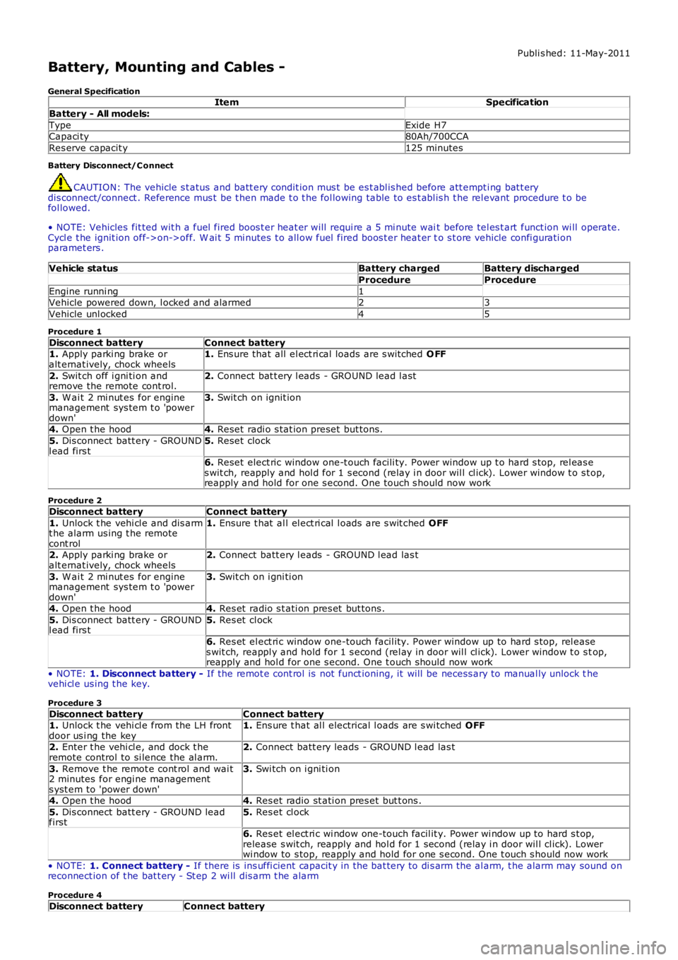
Vehicle statusBattery chargedBattery discharged
ProcedureProcedure
Engine runni ng1Vehicle powered down, l ocked and alarmed23
Vehicle unl ocked45
Procedure 1
Disconnect batteryConnect battery1. Apply parki ng brake oralt ernat ively, chock wheels1. Ens ure that all el ect ri cal loads are s wit ched O FF
2. Swit ch off i gni ti on andremove the remote cont rol.2. Connect bat t ery l eads - GROUND lead l ast
3. W ai t 2 mi nut es for enginemanagement sys tem t o 'powerdown'
3. Swit ch on ignit ion
4. Open t he hood4. Reset radi o s tat ion preset but tons .
5. Dis connect batt ery - GROUNDl ead firs t5. Reset clock
6. Reset elect ric window one-t ouch facili ty. Power window up t o hard s top, rel eas es wit ch, reapply and hol d for 1 s econd (relay i n door wil l cl ick). Lower window t o s top,reapply and hold for one s econd. One t ouch s hould now work
Procedure 2
Disconnect batteryConnect battery
1. Unlock t he vehi cl e and dis armt he alarm us ing t he remotecont rol
1. Ensure t hat al l el ect ri cal l oads are s wit ched OFF
2. Apply parki ng brake oralt ernat ively, chock wheels2. Connect batt ery l eads - GROUND l ead las t
3. W ai t 2 mi nut es for enginemanagement sys tem t o 'powerdown'
3. Swit ch on i gni ti on
4. Open t he hood4. Res et radio s t ati on pres et but tons .
5. Dis connect batt ery - GROUNDl ead firs t5. Res et cl ock
6. Res et el ect ri c window one-touch facil it y. Power window up to hard s top, rel eases wit ch, reappl y and hold for 1 s econd (rel ay in door wil l cl ick). Lower window t o s top,reapply and hol d for one s econd. One t ouch should now work
• NOTE: 1. Disconnect battery - If the remot e cont rol is not funct ioning, it will be necess ary to manual ly unlock thevehi cl e us ing t he key.
Procedure 3
Disconnect batteryConnect battery1. Unlock t he vehi cl e from the LH frontdoor us i ng the key1. Ens ure t hat al l electrical l oads are s wi tched OFF
2. Enter t he vehi cl e, and dock t heremote control to si lence the al arm.2. Connect batt ery leads - GROUND l ead las t
3. Remove t he remot e cont rol and wai t2 minutes for engi ne managements yst em to 'power down'
3. Swi tch on i gni ti on
4. Open t he hood4. Res et radio st ati on pres et but t ons .
5. Dis connect batt ery - GROUND leadfirst5. Res et cl ock
6. Res et el ect ri c wi ndow one-touch facil it y. Power wi ndow up to hard s t op,release s wit ch, reapply and hol d for 1 second (relay i n door wil l cl ick). Lowerwi ndow to s top, reapply and hold for one s econd. One t ouch s hould now work
• NOTE: 1. Connect battery - If there is ins uffi cient capacit y in the bat tery to di s arm the al arm, t he alarm may sound onreconnect ion of t he bat t ery - St ep 2 wi ll dis arm t he alarm
Procedure 4
Disconnect batteryConnect battery
Page 1828 of 3229
1. Apply parki ng brake oralt ernat ively, chock wheels1. Ens ure t hat al l elect rical l oads are s wit ched OFF
2. Open t he hood2. Connect batt ery leads - GROUND l ead las t3. Dis connect batt ery -GROUND lead firs t3. Swit ch on i gni ti on
4. Res et radio s t ati on pres et but tons .
5. Res et cl ock
6. Res et el ect ri c window one-touch facil it y. Power wi ndow up to hard s t op, release swit ch,reapply and hol d for 1 s econd (relay i n door wil l cl ick). Lower window t o s top, reapply andhold for one s econd. One t ouch s houl d now work
Procedure 5
Disconnect batteryConnect battery1. Apply parki ng brake oralt ernat ively, chock wheels1. Ens ure t hat al l elect rical l oads are s wit ched OFF
2. Open t he hood2. Connect batt ery leads - GROUND l ead las t
3. Dis connect batt ery -GROUND lead firs t3. Swit ch on i gni ti on
4. Res et radio s t ati on pres et but tons .
5. Res et cl ock
6. Res et el ect ri c window one-touch facil it y. Power wi ndow up to hard s t op, release swit ch,reapply and hol d for 1 s econd (relay i n door wil l cl ick). Lower window t o s top, reapply andhold for one s econd. One t ouch s houl d now work
Torque SpecificationsDescriptionNmlb-ft
Batt ery tray to support bracket107
Batt ery terminal nut s107Battery support bracket to body:
M8 nut2418
M8 bol t2418
Page 2054 of 3229
it recei ves an alarm s ignal from t he CJB or the t il t s ens ort he power s upply or t he LIN bus link t o t he CJB is dis rupted.
The t ilt s ens or meas ures the l ongi tudinal and lat eral angl e of the vehicl e over a range of ±16 degrees from the hori zont al.W hen t he acti ve ant i-t heft s ys t em i s armed in volumet ri c mode, the t il t s ens or s tores the current vehi cl e angl es in it smemory and monit ors t he t il t sens or readings. If t he vehi cl e angle changes i n eit her di recti on by more t han the al armli mit , t he ti lt s ensor acti vat es t he s ounder.
If the al arm sys tem is act ive and t he batt ery or t he batt ery backed sounder is di sconnect ed, t he s ounder wil l operatewit hout the vi sual indicati on of the turn s ignal i ndicat ors fl as hing.
Global Open/Close
The global open/cl os e feature all ows the us er t o ful ly rais e/l ower t he wi ndows wit h a s ingle pres s of a remote hands etbutt on. The but ton must be press ed and held for more t han 2 s econds. Ei ther or bot h gl obal open/clos e functi ons can bedis abled us ing a Land Rover approved di agnos ti c s yst em.
• NOTE: Remote global cl os e i s not avai lable in cert ain markets , Nort h American Speci ficat ion (NAS) for exampl e.
Single Point Entry
The s ingle poi nt ent ry feature only unlocks the driver's door and the l iftgate, al l ot her doors remai n locked. A si ngle pres sof the unl ock but ton on the remote hands et wil l unl ock only the driver's door and t he li ft gate, a s econd pres s is requi red tounlock the remaini ng doors .
If the vehicle is double l ocked, the firs t pres s of the unlock butt on on t he remote hands et unl ocks t he dri ver's door and theli ft gate. The remai ning doors revert t o the si ngl e l ocked s tat e and can t herefore be unlocked us ing the i nteri or doorhandl es, t he remot e handset unlock butt on or t he unl ock swi tch on the i nst rument panel swi tchpack.
Changi ng from central locki ng to si ngle point ent ry can be carried out by pres s ing the l ock and unlock butt ons on t heremot e handset s imult aneousl y. The turn s ignal i ndicat ors wil l flas h t o confirm that t he functi on change has beenperformed.
Drive Away Locking
The dri ve away door l ocking feature locks the doors and the lift gat e i f they are unlocked when t he vehi cle reaches a cert ains peed.
On vehicles wi th aut omat ic t rans mis s ion, wit h al l t he doors , li ft gate and hood clos ed and t he gear s elector not in 'P' Parkor 'N' Neutral pos it ion, if t he CJB detects , via a high s peed CAN mes s age from t he Ant i-lock Brake Syst em (ABS) module,t hat t he vehi cle s peed is more t han 7 km/h (5 mph), the doors wil l aut omati cal ly l ock.
On vehicles wi th manual t rans mis s ion, wi th al l the doors , l ift gate and hood cl os ed, if t he CJB detects , via a high s peedCAN mes s age from t he ABS modul e, t hat the vehicle speed i s more than 7 km/h (5 mph), t he doors wi ll automat ically lock.
Remote Handset Additional Features
The remot e handset has convenience butt ons in addit ion to the l ock and unl ock but tons .
Pani c Alarm
The pani c alarm feature allows the us er to act ivate the vehicle alarm s yst em us ing the remote hands et. The 'panic but ton',identi fi ed by a t ri angl e s ymbol, can be pres s ed 3 t imes wit hi n 3 s econds or pres s ed and held for more than 3 seconds toact ivat e t he pani c alarm.
Global Open/Close
A gl obal open and clos e feat ure can be operat ed from t he remote hands et . This feature allows the vehicle windows t o beopened/cl os ed by a s ingle press of t he l ock or unlock butt on. The but ton must be press ed and held for more t han 2s econds t o act ivat e the gl obal open/clos e feat ure. The global open/cl ose feature i s not avail abl e i n all market s .
Liftgate Release
A l iftgat e rel eas e but ton can pres s ed t o unlock and rel eas e t he li ft gate latch only. This will operat e wi th the vehicle lockedand alarmed or unl ocked. If t he vehicle i s locked and alarmed, when t he l iftgate releas e butt on i s pres s ed, t he li ft gate canbe opened wit hout t ri ggering t he alarm s ys tem. W hen the liftgat e is subs equent ly clos ed, the al arm wil l be re-act ivated.
Headlamp Convenience
A headlamp conveni ence but ton can be press ed t o operat e the headlamps to as s is t departure or approach to the vehicle. As ingle press of the but ton wi ll operat e the headlamps for approxi mat el y 25 s econds , aft er whi ch ti me t hey wil lautomat ically turn off. A s econd press of t he butt on wi ll t urn off the headlamps i f the 25 second period has not beenreached. Pres s ing the s t op/s tart but ton wit hin t he 25 s econd period wi ll als o t urn off t he headlamp convenience feature.
Convenience mode
W hen t he vehicle i s unlocked us i ng the unl ock but ton on t he remote hands et , t he vehicl e's electrical s ys t em i ni ti atesconvenience mode. The foll owing s yst ems become acti ve:
Memory - s eat adjus t ment and mirror pos it ionInt eri or and ext erior l ighti ngAudio s ys temIns t rument clus ter mes s age cent reHornCigar li ght er/power socket .
Page 2310 of 3229
2-Emergency key blade3-LH front door handl eThe remote hands et cont ai ns an emergency key blade, conceal ed in t he key fob. The front LH exterior door handleincorporates a mechanical operated door lock that i s conceal ed behind a removable plas ti c cover. The door lock all ows thefront LH door to be mechanicall y unlocked and locked us ing t he emergency key blade in the event that the remote cent rallocki ng operation fai ls, or a vehicl e power fai lure occurs.
W hen the mechanical door lock is us ed t he central l ocking syst em wil l not operat e, and if al ready armed the vehicle al armwi ll s ound when the door is opened. The vehicl e i s not abl e to be doubl e l ocked, or the al arm syst em armed usi ng theemergency key blade.
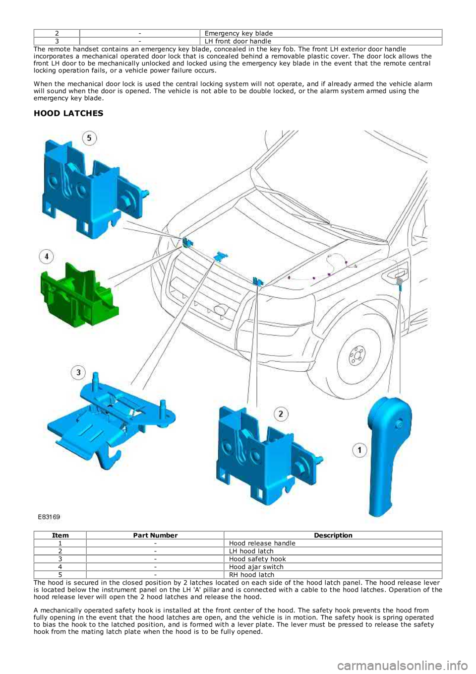
HOOD LATCHES
ItemPart NumberDescription1-Hood release handle2-LH hood lat ch3-Hood s afet y hook4-Hood ajar s witch5-RH hood latchThe hood is s ecured in the clos ed posi tion by 2 latches locat ed on each si de of t he hood l at ch panel. The hood rel ease leveris located bel ow t he inst rument panel on t he LH 'A' pi llar and i s connect ed wit h a cable to t he hood l at ches . Operati on of t hehood releas e lever will open t he 2 hood lat ches and releas e the hood.
A mechanicall y operated safety hook i s i ns talled at the front center of t he hood. The safety hook prevent s t he hood fromfully opening in the event t hat the hood latches are open, and the vehicle is in motion. The safety hook i s s pring operatedto bi as the hook t o t he l atched posi tion, and is formed wit h a lever plat e. The lever must be press ed to release the safetyhook from t he mating lat ch plat e when t he hood is to be full y opened.
Page 2311 of 3229
Hood Ajar Switch
The RH hood lat ch incorporat es the hood ajar s wi tch t hat is hardwired t o t he CJB. If t he i gniti on is in power modes 4(Acces sory) or 6 (Ignit ion) and the hood is opened or is not ful ly closed, t he hood ajar switch is opened t o dis connect theground from t he CJB. A mess age i s trans mitt ed by t he CJB via the medi um s peed CAN bus t o the i ns trument clust er, toinform the dri ver t hat the hood is ajar.
On vehicl es with a low-li ne inst rument clus ter t he hood ajar symbol is i llumi nated.For addit ional informat ion, refer t o: Inst rument Clus ter (413-01 Ins trument Clust er, Des cription and Operat ion).On vehicl es with a high-l ine i ns trument clust er, t he hood ajar s ymbol is il luminat ed and a mes sage i s als o dis pl ayed in t hemess age cent er.For addit ional informat ion, refer t o: Informat ion and Mes sage Center (413-08 Informati on and Mes sage Center, Descriptionand Operat ion).
The hood ajar s wi tch i s als o i nt egrated wit h the vehicle securit y system and is used as the detecti on device for unauthorizedvehicle ent ry.For addit ional informat ion, refer t o: Anti -Theft - Act ive (419-01A Anti-Theft - Act ive, Description and Operat ion).
LIFTGATE LATCH
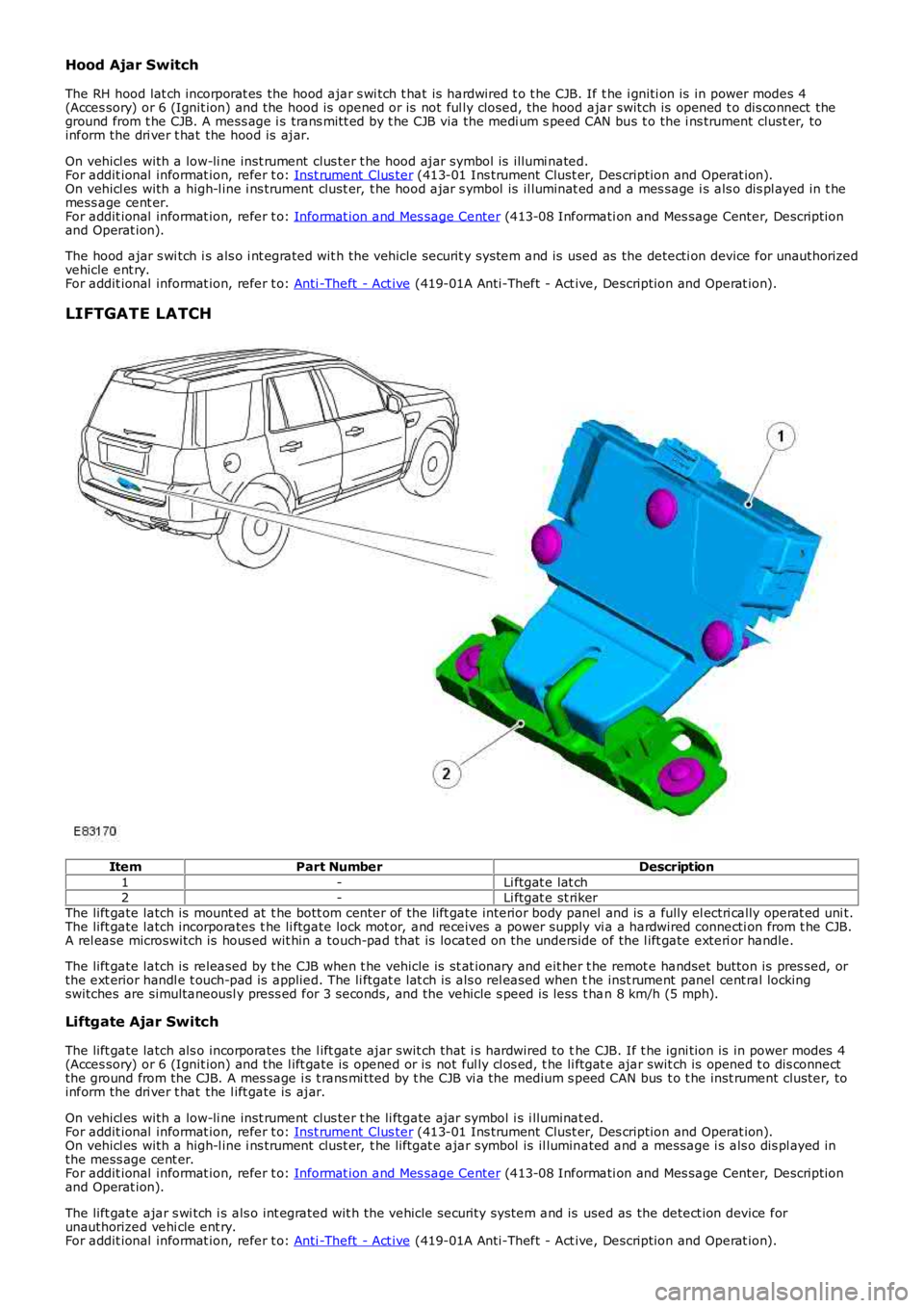
ItemPart NumberDescription
1-Li ftgat e lat ch2-Li ftgat e st rikerThe lift gate latch is mount ed at t he bott om center of the lift gate interior body panel and is a fully el ectri cally operat ed uni t.The lift gate latch incorporates t he li ftgate lock mot or, and receives a power supply vi a a hardwired connecti on from t he CJB.A rel ease microswitch is hous ed wit hin a touch-pad that is located on the unders ide of the l ift gate exteri or handle.
The lift gate latch is released by t he CJB when t he vehicle is st at ionary and eit her t he remot e handset button is pres sed, orthe ext erior handl e t ouch-pad is applied. The li ftgat e lat ch is als o rel eased when the inst rument panel cent ral lockingswitches are simultaneousl y press ed for 3 seconds, and the vehicle s peed is less t han 8 km/h (5 mph).
Liftgate Ajar Switch
The lift gate latch als o incorporates the l ift gate ajar swit ch that i s hardwired to the CJB. If t he igni tion is in power modes 4(Acces sory) or 6 (Ignit ion) and the l ift gate is opened or is not ful ly cl os ed, t he li ftgat e ajar swit ch is opened t o dis connectthe ground from the CJB. A mes sage i s t rans mi tted by t he CJB vi a t he medium s peed CAN bus t o t he inst rument cluster, toinform the dri ver t hat the l ift gate is ajar.
On vehicl es with a low-li ne inst rument clus ter t he li ftgate ajar symbol i s i lluminated.For addit ional informat ion, refer t o: Inst rument Clus ter (413-01 Ins trument Clust er, Des cription and Operat ion).On vehicl es with a high-l ine i ns trument clust er, t he liftgat e ajar symbol is il luminated and a message i s als o dis pl ayed inthe mess age cent er.For addit ional informat ion, refer t o: Informat ion and Mes sage Center (413-08 Informati on and Mes sage Center, Descriptionand Operat ion).
The lift gate ajar s wi tch i s als o int egrated wit h the vehicle securit y system and is used as the detect ion device forunauthorized vehi cle ent ry.For addit ional informat ion, refer t o: Anti -Theft - Act ive (419-01A Anti-Theft - Act ive, Description and Operat ion).
Page 2316 of 3229
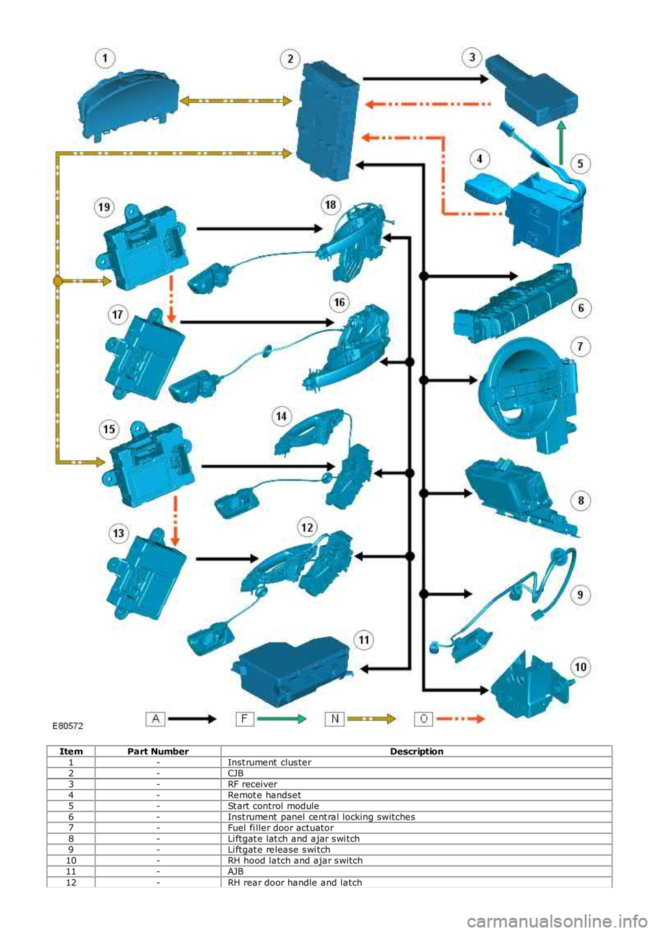
ItemPart NumberDescription1-Inst rument clus ter2-CJB3-RF receiver4-Remot e handset5-St art control module6-Inst rument panel cent ral locking switches7-Fuel fi ller door actuator8-Li ftgat e lat ch and ajar s wi tch9-Li ftgat e release s wi tch10-RH hood latch and ajar s witch11-AJB
12-RH rear door handle and latch