2006 LAND ROVER FRELANDER 2 infotainment
[x] Cancel search: infotainmentPage 108 of 3229
Publ is hed: 28-Apr-2011
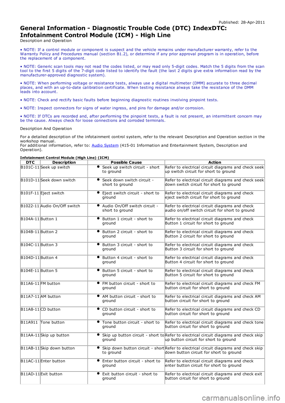
General Information - Diagnostic Trouble Code (DTC) IndexDTC:
Infotainment Control Module (ICM) - High Line
Des cript ion and Operat ion
• NOTE: If a cont rol module or component i s s uspect and the vehicl e remai ns under manufacturer warrant y, refer t o t heW arranty Pol icy and Procedures manual (s ect ion B1.2), or determine i f any pri or approval program is i n operat ion, beforet he replacement of a component.
• NOTE: Generic scan t ool s may not read the codes li st ed, or may read only 5-digi t codes . Match t he 5 digi ts from t he s cant ool t o t he fi rs t 5 di gi ts of the 7-digit code li s ted t o i dent ify the fault (the last 2 digi ts gi ve ext ra informati on read by themanufacturer-approved di agnos ti c s ys t em).
• NOTE: W hen performing volt age or res is t ance t est s , always use a digi tal mult imeter (DMM) accurat e t o t hree deci malplaces, and wi th an up-t o-date cal ibrat ion cert ificate. W hen tes ti ng res is t ance al ways take t he res is t ance of t he DMMleads i nt o account .
• NOTE: Check and recti fy bas ic faul ts before beginni ng diagnos t ic rout ines i nvol vi ng pinpoint t es t s.
• NOTE: Ins pect connect ors for s igns of water ingres s , and pins for damage and/or corros ion.
• NOTE: If DTCs are recorded and, aft er performi ng the pi npoi nt tes ts , a fault is not present , an int ermi tt ent concern maybe t he caus e. Always check for loose connect ions and corroded terminals .
Des cript ion And Operat ion
For a detail ed descripti on of the infot ainment cont rol s ys t em, refer to t he relevant Des cript ion and O perati on sect ion i n theworks hop manual .For addit ional informat ion, refer t o: Audi o Sys tem (415-01 Informati on and Entertainment Sys tem, Des cript ion andOperat ion).
Infotainment C ontrol Module (High Line) (IC M)
DT CDescriptionPossible CauseAction
B101C-11Seek up s wit chSeek up s wi tch circui t - s hortt o groundRefer to electrical ci rcuit diagrams and check s eekup s wit ch ci rcuit for short to ground
B101D-11Seek down s wit chSeek down s wi tch circui t -s hort t o groundRefer to electrical ci rcuit diagrams and check s eekdown s wit ch ci rcuit for short to ground
B101F-11Eject s wit chEject s wi tch circui t - s hort togroundRefer to electrical ci rcuit diagrams and checkeject swit ch ci rcuit for s hort t o ground
B1022-11Audio On/Off s wi tchAudio On/Off s wit ch ci rcuit -s hort t o groundRefer to electrical ci rcuit diagrams and checkaudi o on/off swi tch ci rcuit for s hort t o ground
B104A-11Butt on 1But ton 1 circuit - short togroundRefer to electrical ci rcuit diagrams and checkButt on 1 circui t for s hort t o ground
B104B-11Butt on 2But ton 2 circuit - short togroundRefer to electrical ci rcuit diagrams and checkButt on 2 circui t for s hort t o ground
B104C-11Butt on 3But ton 3 circuit - short togroundRefer to electrical ci rcuit diagrams and checkButt on 3 circui t for s hort t o ground
B104D-11Butt on 4But ton 4 circuit - short togroundRefer to electrical ci rcuit diagrams and checkButt on 4 circui t for s hort t o ground
B104E-11Butt on 5But ton 5 circuit - short togroundRefer to electrical ci rcuit diagrams and checkButt on 5 circui t for s hort t o ground
B11A6-11FM but tonFM but t on ci rcuit - s hort t ogroundRefer to electrical ci rcuit diagrams and check FMbut t on ci rcuit for short to ground
B11A7-11AM but tonAM butt on circuit - short togroundRefer to electrical ci rcuit diagrams and check AMbut t on ci rcuit for short to ground
B11A8-11CD but tonCD butt on circuit - short togroundRefer to electrical ci rcuit diagrams and check CDbut t on ci rcuit for short to ground
B11A911Tone butt onTone but ton circui t - s hort t ogroundRefer to electrical ci rcuit diagrams and check t onebut t on ci rcuit for short to ground
B11AA-11Skip up but tonSkip up butt on circuit - short togroundRefer to electrical ci rcuit diagrams and check s kipup butt on circuit for s hort to ground
B11AB-11Skip down but tonSkip down butt on circuit - shortt o groundRefer to electrical ci rcuit diagrams and check s kipdown butt on circuit for s hort to ground
B11AC-11Enter butt onEnt er but ton ci rcuit - s hort t ogroundRefer to electrical ci rcuit diagrams and checkent er butt on circuit for s hort to ground
B11AD-11Exit butt onExit but ton ci rcuit - s hort t ogroundRefer to electrical ci rcuit diagrams and check exitbut t on ci rcuit for short to ground
Page 111 of 3229
Publ is hed: 28-Apr-2011
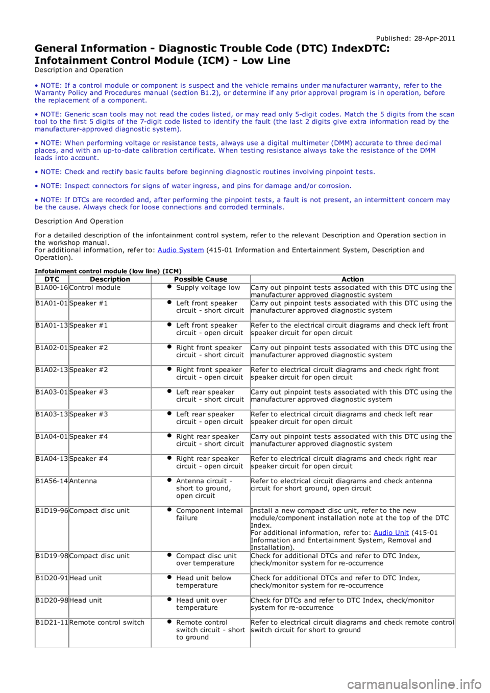
General Information - Diagnostic Trouble Code (DTC) IndexDTC:
Infotainment Control Module (ICM) - Low Line
Des cript ion and Operat ion
• NOTE: If a cont rol module or component i s s uspect and the vehicl e remai ns under manufacturer warrant y, refer t o t heW arranty Pol icy and Procedures manual (s ect ion B1.2), or determine i f any pri or approval program is i n operat ion, beforet he replacement of a component.
• NOTE: Generic scan t ool s may not read the codes li st ed, or may read only 5-digi t codes . Match t he 5 digi ts from t he s cant ool t o t he fi rs t 5 di gi ts of the 7-digit code li s ted t o i dent ify the fault (the last 2 digi ts gi ve ext ra informati on read by themanufacturer-approved di agnos ti c s ys t em).
• NOTE: W hen performing volt age or res is t ance t est s , always use a digi tal mult imeter (DMM) accurat e t o t hree deci malplaces, and wi th an up-t o-date cal ibrat ion cert ificate. W hen tes ti ng res is t ance al ways take t he res is t ance of t he DMMleads i nt o account .
• NOTE: Check and recti fy bas ic faul ts before beginni ng diagnos t ic rout ines i nvol vi ng pinpoint t es t s.
• NOTE: Ins pect connect ors for s igns of water ingres s , and pins for damage and/or corros ion.
• NOTE: If DTCs are recorded and, aft er performi ng the pi npoi nt tes ts , a fault is not present , an int ermi tt ent concern maybe t he caus e. Always check for loose connect ions and corroded terminals .
Des cript ion And Operat ion
For a detail ed descripti on of the infont ai nment cont rol s ys t em, refer t o t he rel evant Des cript ion and Operat ion secti on int he works hop manual .For addit ional informat ion, refer t o: Audi o Sys tem (415-01 Informati on and Entertainment Sys tem, Des cript ion andOperat ion).
Infotainment control module (low line) (IC M)
DT CDescriptionPossible CauseAction
B1A00-16Control modul eSuppl y volt age lowCarry out pi npoi nt tes ts ass ociated wit h t hi s DTC us ing t hemanufacturer approved diagnost ic sys tem
B1A01-01Speaker #1Left front s peakercircui t - short ci rcuitCarry out pi npoi nt tes ts ass ociated wit h t hi s DTC us ing t hemanufacturer approved diagnost ic sys tem
B1A01-13Speaker #1Left front s peakercircui t - open ci rcuitRefer t o the el ect ri cal circui t diagrams and check left fronts peaker ci rcuit for open ci rcuit
B1A02-01Speaker #2Right front s peakercircui t - short ci rcuitCarry out pi npoi nt tes ts ass ociated wit h t hi s DTC us ing t hemanufacturer approved diagnost ic sys tem
B1A02-13Speaker #2Right front s peakercircui t - open ci rcuitRefer t o electrical ci rcuit diagrams and check right fronts peaker ci rcuit for open ci rcuit
B1A03-01Speaker #3Left rear s peakercircui t - short ci rcuitCarry out pi npoi nt tes ts ass ociated wit h t hi s DTC us ing t hemanufacturer approved diagnost ic sys tem
B1A03-13Speaker #3Left rear s peakercircui t - open ci rcuitRefer t o electrical ci rcuit diagrams and check l eft rears peaker ci rcuit for open ci rcuit
B1A04-01Speaker #4Right rear s peakercircui t - short ci rcuitCarry out pi npoi nt tes ts ass ociated wit h t hi s DTC us ing t hemanufacturer approved diagnost ic sys tem
B1A04-13Speaker #4Right rear s peakercircui t - open ci rcuitRefer t o electrical ci rcuit diagrams and check right rears peaker ci rcuit for open ci rcuit
B1A56-14AntennaAntenna circui t -s hort t o ground,open circuit
Refer t o electrical ci rcuit diagrams and check antennacircuit for s hort ground, open circui t
B1D19-96Compact di sc uni tComponent i nternalfai lureIns t al l a new compact di s c uni t, refer t o t he newmodule/component i nst all ati on not e at t he t op of the DTCIndex.For addit ional informat ion, refer t o: Audi o Unit (415-01Informat ion and Ent ert ai nment Sys t em, Removal andIns t al lat ion).
B1D19-98Compact di sc uni tCompact di sc uni tover t emperat ureCheck for addi ti onal DTCs and refer to DTC Index,check/moni tor s ys t em for re-occurrence
B1D20-91Head unitHead unit belowt emperatureCheck for addi ti onal DTCs and refer to DTC Index,check/moni tor s ys t em for re-occurrence
B1D20-98Head unitHead unit overt emperatureCheck for DTCs and refer t o DTC Index, check/monit ors ys t em for re-occurrence
B1D21-11Remote cont rol s wit chRemote cont rols wit ch circuit - shortt o ground
Refer t o electrical ci rcuit diagrams and check remote controls wit ch ci rcuit for short to ground
Page 589 of 3229

1-Pres s t o s wit ch between radi o, CD, or AUX
2-Pres s t o i ncreas e volume
3-Pres s t o decrease vol ume4-Pres s and release to scrol l through preset radi o s t at ions or CD tracks . Pres s to search up or down fort he next or previous radio s t at ion/CD t rack
The audi o control s wi tches are res is ti ve ladder swi tches. Thes e s wit ches connect t o t he Infotainment Control Modul e (ICM)or Int egrated Audi o Modul e (IAM) (dependant upon the l evel of audi o fit ted t o t he vehicle) via t he clockspring.
For addit ional informat ion, refer t o: Audi o Sys tem (415-01, Des cript ion and Operat ion).
Speed Control Switches
ItemPart NumberDescription
1-Set t arget speed, or increase s peed
2-Set t arget speed, or decreas e s peed3-Res ume s et s peed
4-Cancel s s peed cont rol operati on wit hout erasi ng memorized s peed
The s peed control swit ches are res is t ive l adder type. The s ignals from the res is ti ve ladder are fed t o the st eeri ng col umnmodule (located in t he clocks pri ng) which t hen out put s t he s ignals as a local i nterconnect net work (LIN) bus s ignal to thecent ral junct ion box (CJB). The CJB trans mi ts speed cont rol s ignals on the hi gh s peed controll er area network (CAN) bus t ot he engi ne cont rol module (ECM).
For addit ional informat ion, refer t o: Speed Cont rol (310-03A Speed Cont rol - I6 3.2L Petrol, Des cript ion and Operat ion).
For addit ional informat ion, refer t o: Speed Cont rol - 2.2L Di esel (310-03, Des cri ption and Operati on).
Page 1837 of 3229
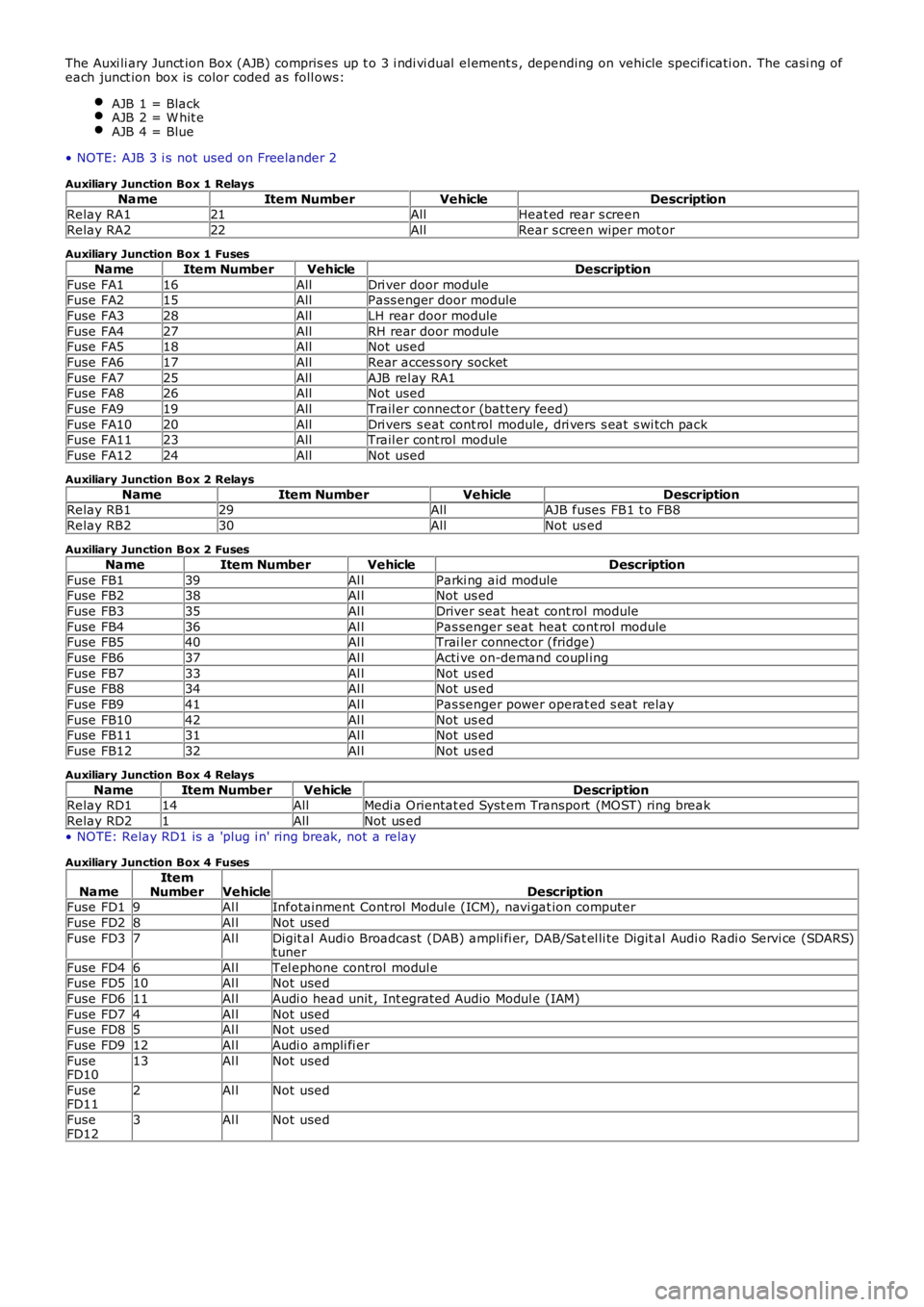
The Auxi li ary Junct ion Box (AJB) compris es up t o 3 i ndi vi dual el ement s , depending on vehicle specificati on. The casi ng ofeach junct ion box is color coded as foll ows:
AJB 1 = BlackAJB 2 = W hit eAJB 4 = Blue
• NOTE: AJB 3 i s not used on Freelander 2
Auxiliary Junction Box 1 Relays
NameItem NumberVehicleDescriptionRelay RA121AllHeat ed rear s creen
Relay RA222AllRear s creen wiper mot or
Auxiliary Junction Box 1 Fuses
NameItem NumberVehicleDescription
Fuse FA116AllDri ver door moduleFuse FA215AllPass enger door module
Fuse FA328AllLH rear door module
Fuse FA427AllRH rear door moduleFuse FA518AllNot used
Fuse FA617AllRear acces s ory socket
Fuse FA725AllAJB rel ay RA1Fuse FA826AllNot used
Fuse FA919AllTrail er connect or (bat tery feed)
Fuse FA1020AllDri vers s eat cont rol module, dri vers s eat s wi tch packFuse FA1123AllTrail er cont rol module
Fuse FA1224AllNot used
Auxiliary Junction Box 2 Relays
NameItem NumberVehicleDescriptionRelay RB129AllAJB fuses FB1 t o FB8
Relay RB230AllNot us ed
Auxiliary Junction Box 2 Fuses
NameItem NumberVehicleDescription
Fuse FB139Al lParki ng aid moduleFuse FB238Al lNot us ed
Fuse FB335Al lDriver seat heat cont rol module
Fuse FB436Al lPas senger seat heat cont rol moduleFuse FB540Al lTrai ler connector (fridge)
Fuse FB637Al lActi ve on-demand coupl ing
Fuse FB733Al lNot us edFuse FB834Al lNot us ed
Fuse FB941Al lPas senger power operat ed s eat relay
Fuse FB1042Al lNot us edFuse FB1131Al lNot us ed
Fuse FB1232Al lNot us ed
Auxiliary Junction Box 4 Relays
NameItem NumberVehicleDescriptionRelay RD114AllMedi a Orientat ed Syst em Transport (MOST) ring break
Relay RD21AllNot us ed
• NOTE: Relay RD1 is a 'plug i n' ring break, not a relay
Auxiliary Junction Box 4 Fuses
NameItemNumberVehicleDescriptionFuse FD19Al lInfotainment Control Modul e (ICM), navi gat ion computer
Fuse FD28Al lNot used
Fuse FD37Al lDigit al Audi o Broadcast (DAB) ampli fi er, DAB/Sat el li te Digit al Audi o Radi o Servi ce (SDARS)tuner
Fuse FD46Al lTel ephone control modul eFuse FD510Al lNot used
Fuse FD611Al lAudi o head unit , Int egrated Audio Modul e (IAM)
Fuse FD74Al lNot usedFuse FD85Al lNot used
Fuse FD912Al lAudi o ampli fi er
FuseFD1013Al lNot used
FuseFD112Al lNot used
FuseFD123Al lNot used
Page 1888 of 3229
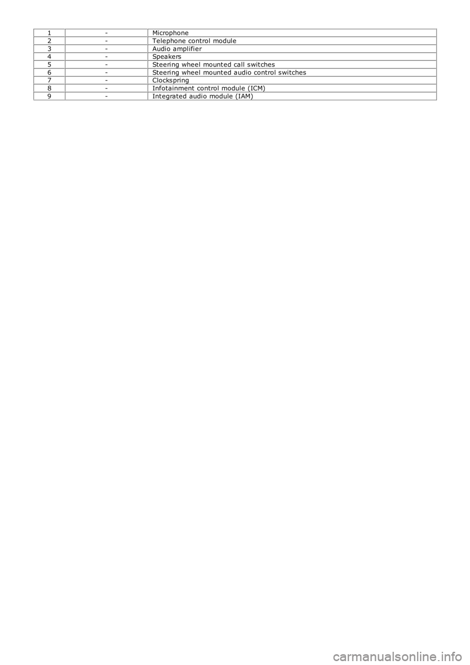
1-Microphone
2-Telephone control modul e
3-Audi o ampl ifi er4-Speakers
5-Steeri ng wheel mount ed call s wit ches
6-Steeri ng wheel mount ed audio control s wi tches7-Clocks pring
8-Infotainment control modul e (ICM)
9-Int egrated audi o module (IAM)
Page 1892 of 3229
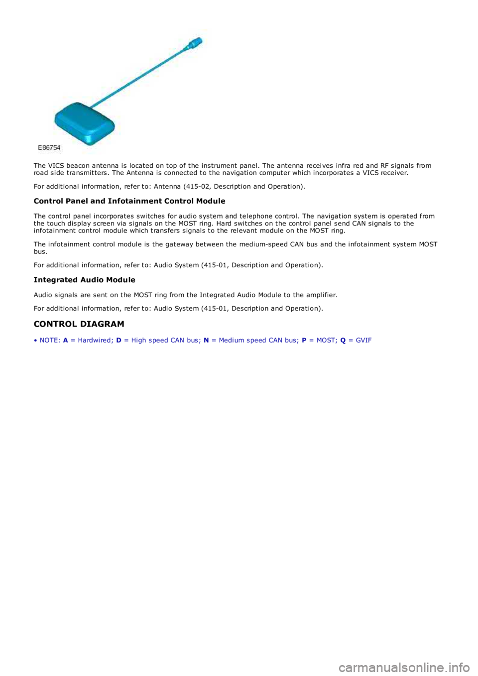
The VICS beacon antenna i s located on t op of t he ins trument panel. The ant enna receives infra red and RF s ignals fromroad s i de transmit ters . The Ant enna i s connected t o t he navigati on comput er which incorporat es a VICS receiver.
For addit ional informat ion, refer t o: Antenna (415-02, Des cri pt ion and Operati on).
Control Panel and Infotainment Control Module
The cont rol panel i ncorporates s wi tches for audio s ys tem and tel ephone cont rol . The navi gat ion s ys tem is operat ed fromt he touch dis play s creen via si gnal s on t he MOST ring. Hard swi tches on t he cont rol panel s end CAN s i gnals to theinfotainment control modul e which t rans fers s ignal s t o t he rel evant module on the MOST ri ng.
The infotainment control modul e is the gat eway bet ween the medium-speed CAN bus and t he i nfotai nment s ys tem MOSTbus.
For addit ional informat ion, refer t o: Audi o Sys tem (415-01, Des cript ion and Operat ion).
Integrated Audio Module
Audio s ignals are s ent on t he MOST ring from the Integrat ed Audio Modul e to the amplifier.
For addit ional informat ion, refer t o: Audi o Sys tem (415-01, Des cript ion and Operat ion).
CONTROL DIAGRAM
• NOTE: A = Hardwi red; D = Hi gh s peed CAN bus ; N = Medi um s peed CAN bus; P = MOST; Q = GVIF