2006 LAND ROVER FRELANDER 2 glove box
[x] Cancel search: glove boxPage 1830 of 3229
• NOTE: The fus i bl e l inks are mount ed on t he inboard s i de of the BJB behind a series of removable covers .
The CJB is mount ed behind t he glovebox and recei ves it s main power s uppl y from the BJB. In addi ti on to cont aining bl adefus es , the CJB i s t he main controll er for a number of vehicle s ys t ems. Thes e functi ons are out li ned in t he rel evant s ect ionsof thi s manual .
The AJB is locat ed beneat h t he luggage compartment carpet , adjacent t he spare wheel wel l. The AJB i s a modular des ign,and compris es up t o 3 individual elements depending on vehicle specificati on. The AJB cont ains bl ade and J-cas e fuses ,and rel ays to di st ribute el ect ri cal power to sys t ems used at the rear of t he vehi cle. The AJB receives it s mai n power s upplyfrom the BJB.
Starter Fuse
ItemPart NumberDescription
1-Starter fus e
Incorporat ed i n the cable bet ween t he bat t ery and t he s tarter mot or/generat or is a CAL3 st art er fus e. The fus e is mount edadjacent t he batt ery pos it ive t erminal and is i ntegral wi th t he cable as s embly. In the event of fus e fai lure, t he completecabl e as sembl y mus t be repl aced.
Wire Color Codes
New wi re col or codes have been i ntroduced i n the El ect ri cal Ci rcuit Di agrams . Thes e new codes are s hown i n t he tablebelow.
ColorCode
BlackBK
BlueBUBrownBN
GreenGN
GreyGYOrangeOG
RedRD
Viol etVTW hi teW H
Y ell owY E
Tracer wire col or codes are s eparat ed from the main wi re col or code by a hyphen, t hus BU-RD equat es to a blue wire wit h ared tracer. For more informat ion, refer to t he Elect rical Circui t Diagrams and the El ect ri cal Library.
POWER MODES
The CJB cont rol s the power s uppl ies for the vari ous vehi cl e functi ons. There are 9 power modes availabl e which are usedby vari ous s ys tems to det ermi ne t he operati ng condit ion of t he vehi cle. Only 3 of thes e modes wil l be noti ceable t o t hedri ver and t echnici ans as foll ows:
Power mode 4 - Acces s oryPower mode 6 - Igni ti onPower mode 9 - Engine crank.
Transport Mode
All new vehicles will be del ivered from the factory in t rans port mode. Trans port mode repl aces t he t radit ional trans i t relayand inhibi ts a number of el ect ri cal s ys t ems and feat ures t o eli mi nat e quies cent drain from the bat tery during del ivery.W hen t he vehicle i s in transport mode 't rans p' wi ll be di spl ayed i n t he ins trument cl ust er odomet er.
To remove the vehicle from t rans port mode, the Land Rover approved di agnos ti c s ys t em mus t be connect ed during t hePre-Delivery Ins pect ion (PDI). For more i nformati on, refer t o the PDI manual .
Stop/Start Vehicles - From 2010 MY
Component Locat ion
The TD4_e is t he first Land Rover fit t ed wit h an i ntell igent ‘St op/Start’ s yst em; t he fol lowing component s have beenint roduced to support t he Stop/St art vehicle.For addit ional informat ion, refer t o: Starti ng Sys t em (303-06C Starti ng Syst em - TD4 2.2L Di es el, Vehicles Bui lt From:01-03-2009, Descripti on and Operat ion).
Page 1918 of 3229
5-Side turn s ignal l amp
6-Headlamp level ing modul e or Adapt ive Front l ighti ng Sys t em (AFS) control modul e
7-Bat tery Juncti on Box (BJB)8-Column s talk mult ifunct ion s wit ch
9-Revers e l amp s wit ch (Manual trans mi s si on only)
10-Light s wit ch module11-St op lamp swi tch
12-Front height s ens or (Xenon headlamps only)
13-Refl ect or14-Rear lamp as s embly
15-License plate lamps
16-Hi gh mounted s t op lamp17-Central Juncti on Box (CJB)
18-Front fog lamp
19-Headlamp as s embly
OVERVIEW
Three l evel s of ext eri or l ighti ng are avai lable dependi ng on vehicle s peci fi cat ion:
Halogen headl ampsBi-xenon Hi gh Int ensi ty Dis charge (HID) headl ampsBi-xenon HID Adapt ive Front li ghti ng Sys t em (AFS) headlamps .
A l ight s wit ch module i s located i n t he ins t rument panel and all ows t he driver t o s elect the appropri ate operat ion of t heexteri or li ght ing s ys tems .
The rear l amp as sembl ies cont ain si de lamps , s top lamps , revers e l amps , t urn s i gnal indi cat ors and rear fog lamps . OnNort h American Speci ficat ion (NAS) vehicles the rear l amp as s embly als o incl udes a side marker l amp. The rear lampas sembl ies requi re removal for bul b repl acement. Two reflect ors are mount ed in the rear bumper.
All vers ions of t he headl amps have impact res is t ant polycarbonat e l ens '. Removable covers at t he rear of t he headl ampsall ow for bulb replacement. The headlamps requi re removal for bul b repl acement.
The halogen headl amps have large complex surface reflectors to opt imis e t he beam patt erns i n l ow beam only. A hi ghbeam only refl ect or is l ocat ed on t he inboard s i de of the headlamp. Headl amp l evel ing on t he halogen headl amps ismanually adjust ed us ing a rot ary t humbwheel located i n t he li ght swi tch modul e which operat es leveling motors located i nt he headlamp.
The bi-functi on HID headl amps and the AFS headlamps us e a projector unit wit h a D1S xenon bulb whi ch operates i n bothlow and high beam. An addit ional hal ogen hi gh beam only refl ect or is l ocat ed on t he inboard s ide of t he headlamp.Headl amp l evel ing i s aut omat ic on t he HID headl amps . Front and rear hei ght sens ors are located on the Left Hand (LH)s ide of t he front and rear axl es. Thes e meas ure t he vehi cle at ti tude and a headlamp leveling modul e, which is locat ed ont he bul khead 'A' pi ll ar behind t he glovebox, aut omat icall y cont rol s t he headlamp vert ical al ignment.
Headl amp powerwas h i s a s t andard fi tment on HID headlamps .
Turn s i gnal indi cat ors and high and low beam functi ons are cont rol led from t he LH s teeri ng column mul ti functi on s wit ch.The t urn s ignal indicators have a lane change feat ure. A s ingle pres s and rel eas e of t he mult ifunct ion s wi tch i n eit herdirect ion wi ll operat e t he sel ect ed t urn s ignal indicators for 3 cycles .
The exteri or li ght ing i s cont rol led by t he CJB. The CJB i s t he main cont roll ing modul e for vehicle body s yst ems and i slocated behind the gl ovebox in the i nst rument panel.
The CJB provides circui t protect ion for al l ext eri or l ighti ng circui ts .
Exterior Bulb Typ e/Rating
The fol lowing table shows t he bulbs us ed for t he exterior li ght ing sys tem and t hei r type and s peci fi cat ion.
BulbT ypeRating
Halogen Headlamps - Low beam - Rest O f W orl d (ROW )Halogen H755W
Halogen Headlamps - Low beam - Nort h American Specificati on (NAS)Halogen H1155WXenon headl amps - Low/Hi gh BeamXenon D1S35W
Headlamps - Hi gh BeamHalogen H755W
Front fog lampsHalogen H1155WRear fog l ampsBayonet P2121W
Turn si gnal i ndi cat or lamps - Front - ROWBayonet PY 21W21W
Turn si gnal i ndi cat or lamps - Front - NASBayonet 7507A or PY 21W21WSide turn s ignal l amps - Up t o 2009MYCapl ess W 5W Clear5W
Side turn s ignal l amps - From 2009MYCapl ess W Y 5W Orange5W
Turn si gnal i ndi cat or lamps - Rear - Up t o 2009MYBayonet PY 21 Orange21WTurn si gnal i ndi cat or lamps - Rear - From 2009MYBayonet Silvervi si on PY 21W SV21W
Side lamps - FrontCapl ess W 5W5W
St op/Tai l lampsBayonet - Twin fil ament P21/521W /5WHi gh mount ed s t op lampW 16W16W
License plate lampsCapl ess W 5W5W
Revers ing l ampsBayonet P2121WNAS - Si de marker lamp (rear)Capl ess W 5W5W
CONTROL DIAGRAM
Page 1953 of 3229
5-Rear door module
6-Rear i nterior lamp
7-Luggage compart ment lamp8-Rear door lat ch swit ch
9-Rear door module
10-Dri ver door lat ch swi tch11-Dri ver door lamp
12-Dri ver door module
13-Ext eri or mirror lamp14-Vani ty mirror l amp
15-Dri ver foot well l amp
16-Pas s enger foot well l amp17-Cent ral Junct ion Box (CJB)
18-Pas s enger door lamp
19-Glovebox lamp20-Pas s enger door module
21-Ext eri or mirror lamp
22-Pas s enger door lat ch swi tch
OVERVIEW
Operat ion of t he int erior l ighti ng s ys t em, wit h t he excepti on of the door and mi rror lamps , is controlled by the CJB. Doorand mi rror l amp operat ion i s cont rol led by t he rel evant door modul e.
In order to cont rol t he int erior l ighti ng s ys t em, the CJB recei ves i nput s from the 4 door l atch s wit ches and the l iftgat erel eas e motor. The s ys tem als o i nt eracts wit h t he cent ral locking s ys tem, i lluminating the interior lamps and the mirrorlamps on receipt of an unlock request . This reques t is trans mi tt ed t o t he CJB from the Radio Frequency (RF) receiver.
The front and rear roof mounted interior lamps contai n a 3 pos i ti on rocker s wi tch. Aut omati c (Courtes y) operati on of thelamps can be overridden by movi ng the s wi tch t o t he 'al ways on' or 'always off' positi on.
If 'Court es y' li ght ing i s acti ve and a hinged panel i s left open, t he CJB wil l ext inguis h all i nterior lamps after a period of 15mi nut es. If a manual request for int erior l ighti ng has been made, t he CJB wi ll exti nguis h the l amps aft er a peri od of 30mi nut es.
Pres s ing t he li ght symbol on t he remot e hands et wi ll act ivat e t he 'Approach Lamp' feat ure. W hen act ivated, t he CJBil lumi nat es t he mirror l amps and a number of ext eri or l amps.For addit ional informat ion, refer t o: Ext eri or Li ght ing (417-01 Ext erior Light ing, Descri pti on and Operat ion).
On vehicles from 2009MY , t he front int erior l amp incorporat es 2 map reading l amps. The front i nt eri or lamp i s fit ted wi th 2addi ti onal s wi tches which cont rol each lamp and operate i ndependant ly of t he i nt eri or light ing funct ionalit y.
Transport Mode
All new vehicles will be del ivered from the factory in t rans port mode. Trans port mode i nhi bit s a number of el ect ri cals ys t ems and feat ures , including t he i nt eri or lamps , to el imi nate qui es cent drain from t he bat t ery duri ng delivery. W hen thevehi cl e i s in trans port mode 't ransp' wi ll be dis played i n the ins trument cl us t er odomet er.
To remove the vehicle from t rans port mode, the Land Rover approved di agnos ti c s ys t em mus t be connect ed during t hePre-Delivery Ins pect ion (PDI). For more i nformati on, refer t o the PDI manual .
CONTROL DIAGRAM
• NOTE: A = Hardwi red; N = Medium s peed Cont roll er Area Net work (CAN) bus
Page 1955 of 3229

12-Rear i nt eri or lamp
13-Front interior lamp (i ncl udes map reading lamps on vehicles from 2009MY )
14-Li ft gate releas e mot or15-Luggage compartment l amp
16-Glovebox l amp
17-Dri ver foot well l amp18-Pas s enger foot well l amp
19-RF receiver
20-CJB21-Dri ver door latch s wi tch
22-Pas s enger door latch s wi tch
23-Dri ver door lamp24-Pas s enger door lamp
25-Ext eri or mirror lamp
26-Bat t ery Junct ion Box (BJB)
PRINCIPLES OF OPERATION
Operat ion and control of t he int eri or l amps can be s plit i nto 3 main groups.
Front and Rear Interior Lamps, Footwell Lamps, and Load Space Lamp
The CJB cont rol s operati on of thes e lamps by providing a vol tage feed to bot h s ides of each lamp. By i ncreas i ng ordecreas i ng the vol tage s uppl ied t o one s ide of t he l amp, the CJB control s t he current flow t hrough t he lamp and thus t heli ght ing level . This feat ure is controlled vi a t he int erior l amp Field Effect Trans is t or (FET), which i s i nt egral wit h t he CJBand all ows the CJB t o ramp up and ramp down t he i lluminati on levels of t he lamps when required. The CJB cont rol s t heramp up t ime to 1.3 s econds , and the ramp down t ime t o 2.6 seconds .
If the vehicle is i nvolved i n an acci dent vi ol ent enough t o t ri gger t he Suppl ement al Res t raint Sys tem (SRS), the Res traint sControl Module (RCM) wi ll provide a 250 Hz 'crash' s ignal to t he CJB. On receipt of t hi s s ignal the CJB wi ll i lluminate thefront and rear int erior l amps, t he foot well l amps and the l oad s pace l amp for up to 30 minut es . The CJB wi ll exti nguis h theint eri or l amps pri or to t he 30 minute period el aps ing if t he cras h s ignal from t he RCM i s replaced wi th a 10 Hz 'normal's ignal.
Vanity Mirror and Glovebox Lamps
The vani ty mirror l amps and the gl ovebox lamp are provi ded a volt age feed by t he CJB. W hen vani ty mirror l amp operati onis sel ect ed by pres s ing t he rel evant s wit ch, a ground path i s creat ed caus ing t he l amp t o il lumi nat e. Glovebox l ampil lumi nat ion is control led by a mi croswi tch whi ch is i ntegral wi th the l amp as sembl y. W hen t he glovebox i s opened, t hes wit ch cont act s clos e creati ng a ground pat h for t he l amp.
Door and Mirror Lamps
Operat ion of t he door and mirror lamps i s cont rol led by t he door modul es in conjuncti on wit h t he CJB. The CJB provi des afeed t o each door latch s wi tch. W hen a door is opened, the s wi tch contacts cl os e provi ding a feed t o t he relevant doormodule. On recei pt of t his feed, t he module il luminat es it s door lamp by provi ding a feed and ground path.
The dri ver and front pass enger door modules al so cont rol operati on of the mirror lamps . W hen a val id unl ock reques t isreceived from the RF recei ver, t he CJB not ifies t he dri ver and front pas senger door modules vi a the medium speed CANbus. On receipt of the CAN bus mes sage t he door modul e i llumi nates t he rel evant mi rror lamp by provi ding a feed andground path.
Page 1970 of 3229
Publi s hed: 11-May-2011
Module Communications Network - Central Junction Box (CJB)
Removal and Inst all ati on
Removal
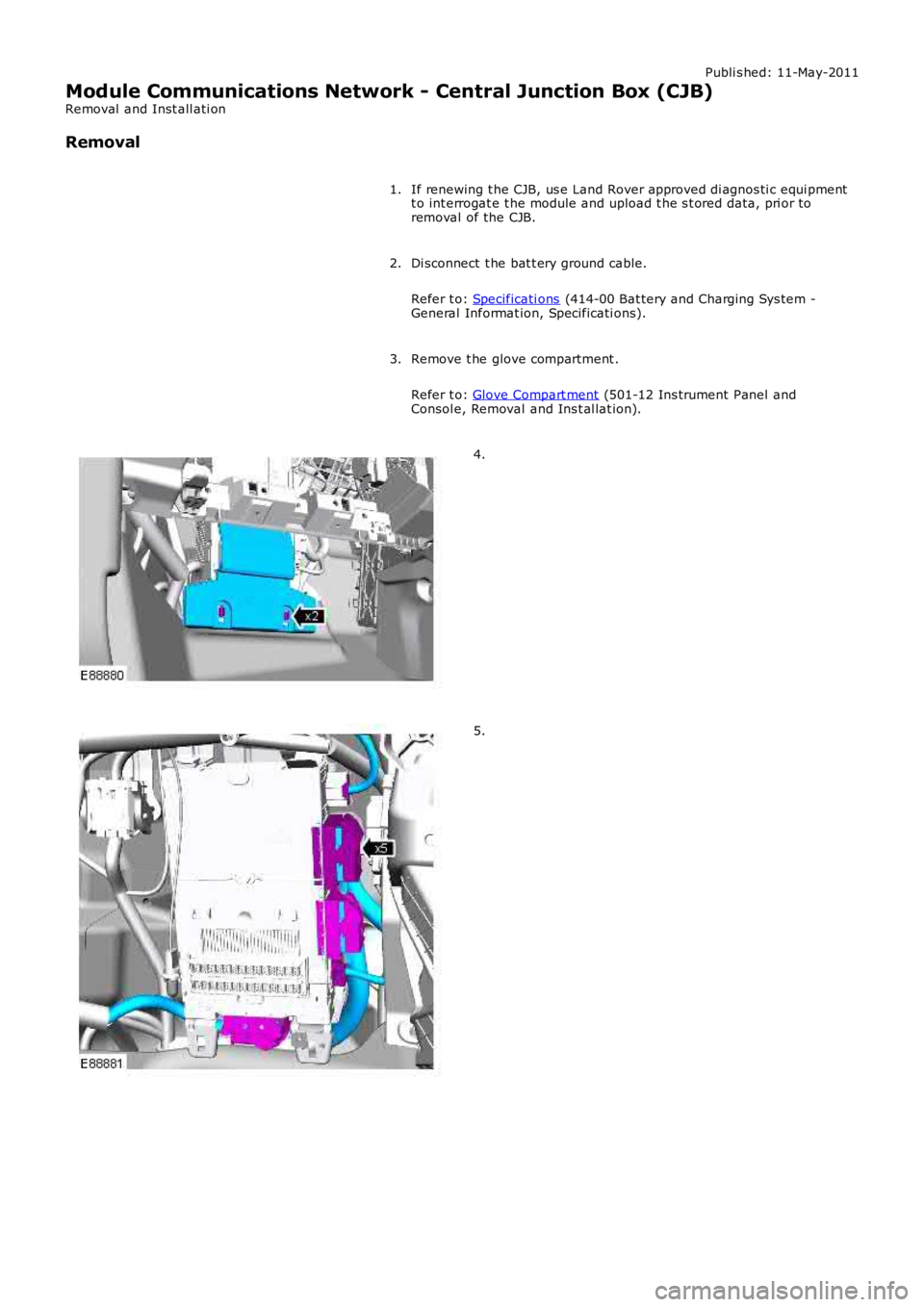
If renewing t he CJB, us e Land Rover approved di agnos ti c equi pmentt o int errogat e t he module and upload t he s t ored data, pri or toremoval of the CJB.
1.
Di sconnect t he bat t ery ground cable.
Refer t o: Specificati ons (414-00 Bat tery and Charging Sys tem -General Informat ion, Specificati ons).
2.
Remove t he glove compartment .
Refer t o: Glove Compart ment (501-12 Ins trument Panel andConsol e, Removal and Ins t al lat ion).
3.
4.
5.
Page 1972 of 3229
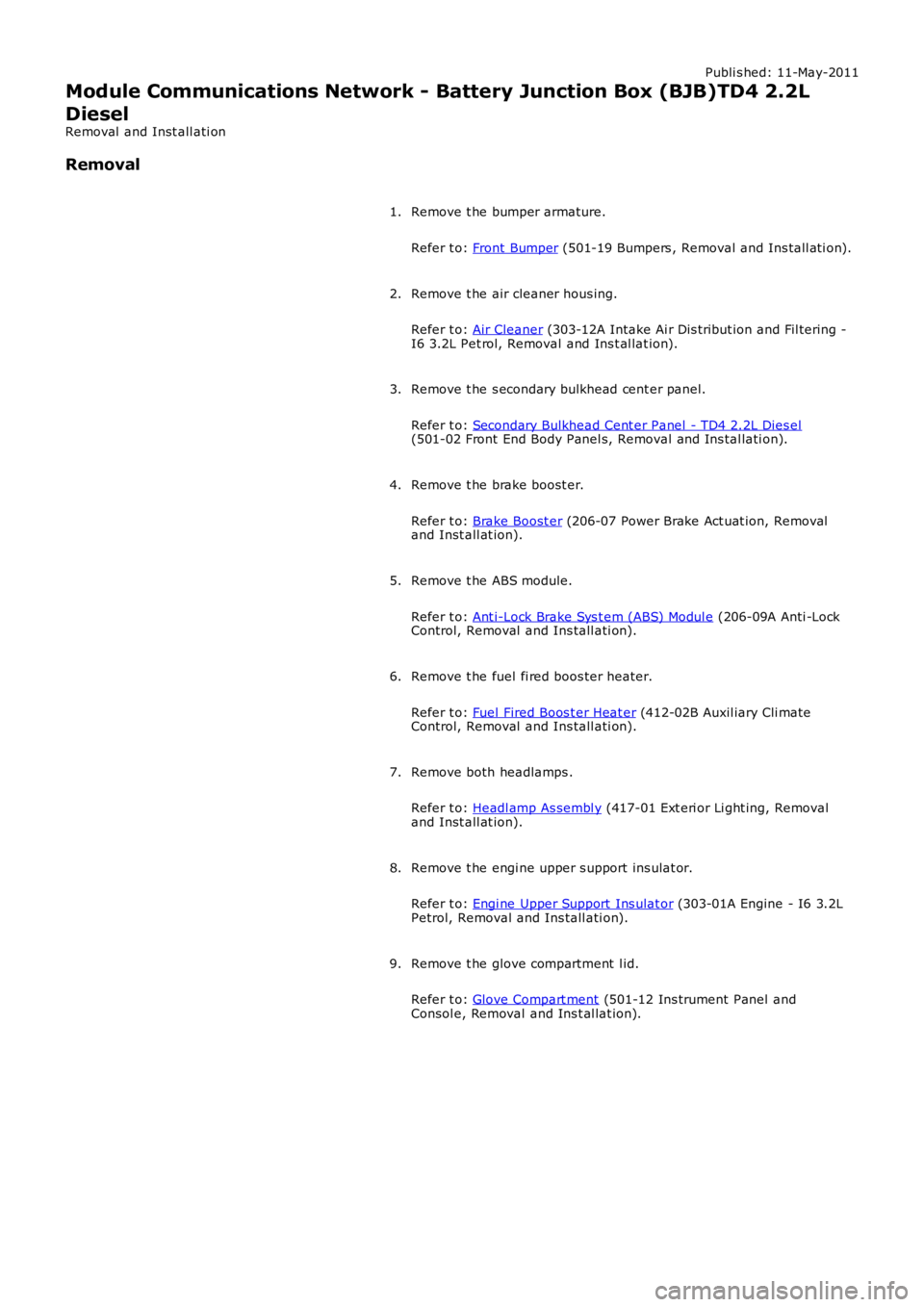
Publi s hed: 11-May-2011
Module Communications Network - Battery Junction Box (BJB)TD4 2.2L
Diesel
Removal and Inst all ati on
Removal
Remove t he bumper armature.
Refer t o: Front Bumper (501-19 Bumpers , Removal and Ins tall ati on).
1.
Remove t he air cleaner hous ing.
Refer t o: Air Cleaner (303-12A Intake Ai r Dis tribut ion and Fil tering -I6 3.2L Pet rol, Removal and Ins t al lat ion).
2.
Remove t he s econdary bulkhead cent er panel.
Refer t o: Secondary Bulkhead Cent er Panel - TD4 2.2L Dies el(501-02 Front End Body Panel s, Removal and Ins tal lati on).
3.
Remove t he brake boost er.
Refer t o: Brake Boost er (206-07 Power Brake Act uat ion, Removaland Inst all at ion).
4.
Remove t he ABS module.
Refer t o: Ant i-Lock Brake Sys t em (ABS) Modul e (206-09A Anti -LockControl, Removal and Ins tall ati on).
5.
Remove t he fuel fi red boos ter heater.
Refer t o: Fuel Fired Boos t er Heat er (412-02B Auxil iary Cli mateControl, Removal and Ins tall ati on).
6.
Remove both headlamps .
Refer t o: Headl amp As sembl y (417-01 Ext eri or Li ght ing, Removaland Inst all at ion).
7.
Remove t he engi ne upper s upport ins ulat or.
Refer t o: Engi ne Upper Support Ins ulat or (303-01A Engine - I6 3.2LPetrol, Removal and Ins tall ati on).
8.
Remove t he glove compartment l id.
Refer t o: Glove Compart ment (501-12 Ins trument Panel andConsol e, Removal and Ins t al lat ion).
9.
Page 1992 of 3229
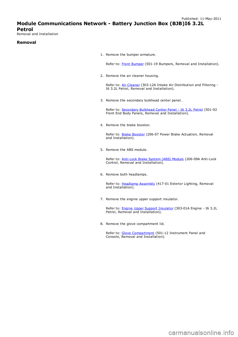
Publi s hed: 11-May-2011
Module Communications Network - Battery Junction Box (BJB)I6 3.2L
Petrol
Removal and Inst all ati on
Removal
Remove t he bumper armature.
Refer t o: Front Bumper (501-19 Bumpers , Removal and Ins tall ati on).
1.
Remove t he air cleaner hous ing.
Refer t o: Air Cleaner (303-12A Intake Ai r Dis tribut ion and Fil tering -I6 3.2L Pet rol, Removal and Ins t al lat ion).
2.
Remove t he s econdary bulkhead cent er panel.
Refer t o: Secondary Bulkhead Cent er Panel - I6 3.2L Pet rol (501-02Front End Body Panel s, Removal and Ins t al lat ion).
3.
Remove t he brake boost er.
Refer t o: Brake Boost er (206-07 Power Brake Act uat ion, Removaland Inst all at ion).
4.
Remove t he ABS module.
Refer t o: Ant i-Lock Brake Sys t em (ABS) Modul e (206-09A Anti -LockControl, Removal and Ins tall ati on).
5.
Remove both headlamps .
Refer t o: Headl amp As sembl y (417-01 Ext eri or Li ght ing, Removaland Inst all at ion).
6.
Remove t he engi ne upper s upport ins ulat or.
Refer t o: Engi ne Upper Support Ins ulat or (303-01A Engine - I6 3.2LPetrol, Removal and Ins tall ati on).
7.
Remove t he glove compartment l id.
Refer t o: Glove Compart ment (501-12 Ins trument Panel andConsol e, Removal and Ins t al lat ion).
8.
Page 2072 of 3229
3-Touch Screen Dis play (TAD)
4-Integrat ed Head Unit (IHU) - Hi-Li ne
5-Bl uet ooth phone module6-Ampl ifier/t uner
7-Di git al Audio Broadcas t (DAB) recei ver
8-Navigat ion computer
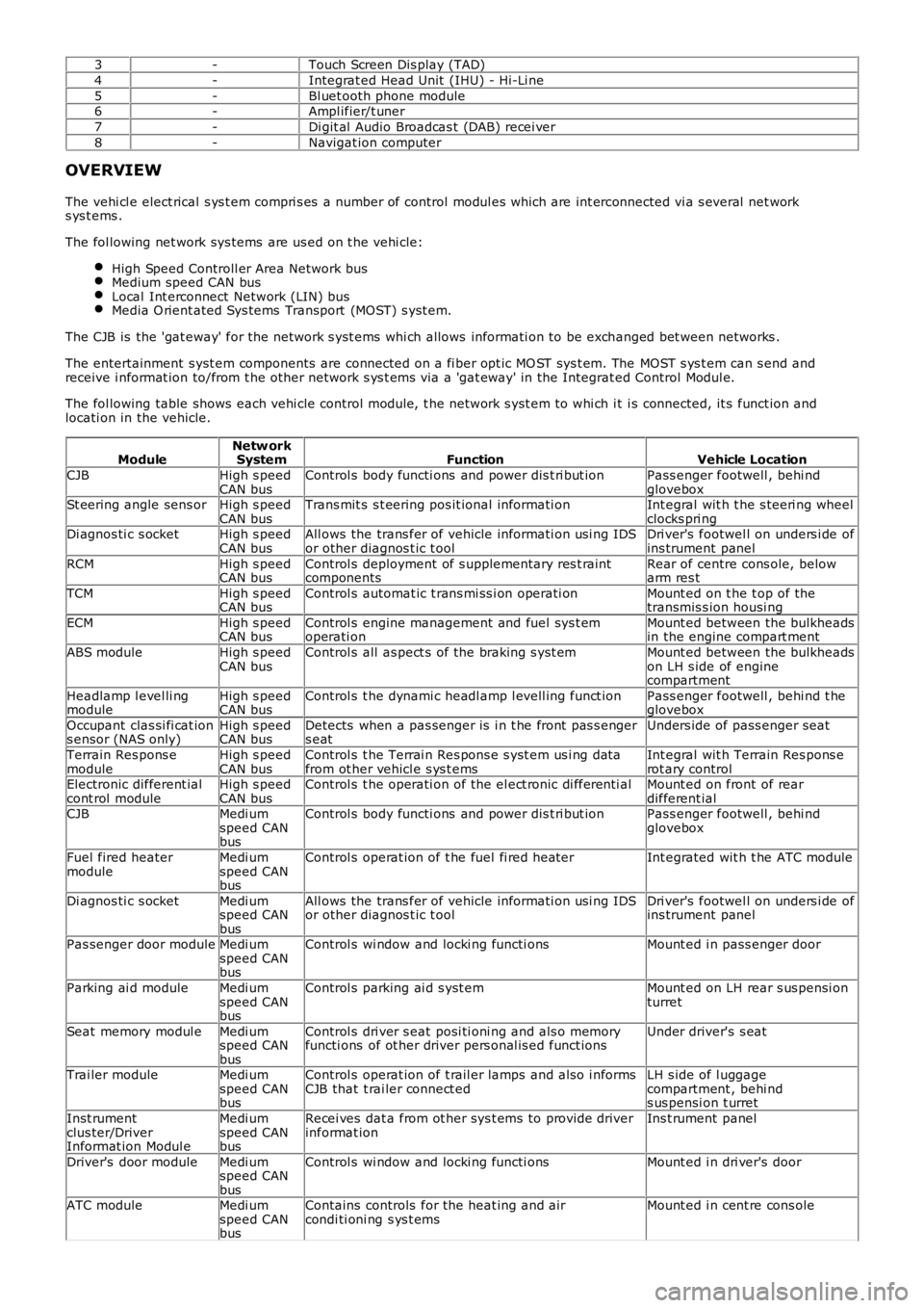
OVERVIEW
The vehi cl e elect rical s ys t em compri s es a number of control modul es which are int erconnected vi a s everal net works ys t ems .
The fol lowing net work sys tems are us ed on t he vehi cle:
High Speed Controll er Area Network busMedium speed CAN busLocal Int erconnect Network (LIN) busMedia O rient ated Sys tems Transport (MOST) s yst em.
The CJB is the 'gat eway' for the net work s yst ems whi ch allows informati on to be exchanged bet ween networks .
The entertainment s yst em components are connected on a fi ber opt ic MO ST sys t em. The MOST s ys t em can s end andreceive i nformat ion to/from t he other network s ys t ems via a 'gat eway' in the Integrat ed Control Modul e.
The fol lowing table shows each vehi cle control modul e, t he network s yst em to whi ch it i s connected, it s funct ion andlocati on in the vehicle.
ModuleNetw orkSystemFunctionVehicle Location
CJBHigh s peedCAN busControl s body functi ons and power dis t ri but ionPass enger footwell , behi ndgloveboxSt eering angle sens orHigh s peedCAN busTrans mit s s t eering pos it ional informati onInt egral wit h t he s teeri ng wheelclocks pri ngDi agnos ti c s ocketHigh s peedCAN busAll ows the trans fer of vehicle informati on usi ng IDSor other diagnos t ic t oolDri ver's footwel l on unders i de ofins trument panel
RCMHigh s peedCAN busControl s deployment of s upplementary res t raintcomponentsRear of centre cons ole, belowarm res t
TCMHigh s peedCAN busControl s automat ic t rans mi ss i on operati onMount ed on t he t op of thetransmis s ion housi ng
ECMHigh s peedCAN busControl s engine management and fuel sys t emoperati onMount ed between the bulkheadsin the engine compart ment
ABS moduleHigh s peedCAN busControl s all as pect s of the braking s yst emMount ed between the bulkheadson LH s ide of enginecompartment
Headlamp l evel li ngmoduleHigh s peedCAN busControl s t he dynami c headl amp l evell ing funct ionPass enger footwell , behi nd t heglovebox
Occupant clas si fi cat ions ensor (NAS only)High s peedCAN busDetects when a pas senger is i n t he front pas s engers eatUnders ide of pass enger seat
Terrain Res pons emoduleHigh s peedCAN busControl s t he Terrai n Res pons e s yst em us i ng dat afrom ot her vehicl e s ys t emsInt egral wit h Terrain Res pons erot ary controlElectronic different ialcont rol moduleHigh s peedCAN busControl s t he operati on of the el ect ronic di fferenti alMount ed on front of reardifferent ialCJBMedi umspeed CANbus
Control s body functi ons and power dis t ri but ionPass enger footwell , behi ndglovebox
Fuel fired heatermoduleMedi umspeed CANbus
Control s operat ion of t he fuel fi red heaterInt egrated wit h t he ATC module
Di agnos ti c s ocketMedi umspeed CANbus
All ows the trans fer of vehicle informati on usi ng IDSor other diagnos t ic t oolDri ver's footwel l on unders i de ofins trument panel
Pas senger door moduleMedi umspeed CANbus
Control s wi ndow and locki ng functi onsMount ed i n pass enger door
Parking ai d moduleMedi umspeed CANbus
Control s parking ai d s yst emMount ed on LH rear s us pensi onturret
Seat memory modul eMedi umspeed CANbus
Control s dri ver s eat posi ti oni ng and als o memoryfuncti ons of ot her driver pers onal is ed funct ionsUnder driver's s eat
Trai ler moduleMedi umspeed CANbus
Control s operat ion of t rail er lamps and als o i nformsCJB that t rai ler connect edLH s ide of l uggagecompartment , behi nds us pensi on t urret
Inst rumentclus ter/DriverInformat ion Modul e
Medi umspeed CANbus
Recei ves dat a from ot her sys t ems to provide driverinformat ionIns t rument panel
Driver's door moduleMedi umspeed CANbus
Control s wi ndow and locki ng functi onsMount ed i n dri ver's door
ATC moduleMedi umspeed CANbus
Contains controls for the heat ing and aircondi ti oni ng s ys t emsMount ed i n cent re cons ole