2006 LAND ROVER FRELANDER 2 lights
[x] Cancel search: lightsPage 73 of 3229
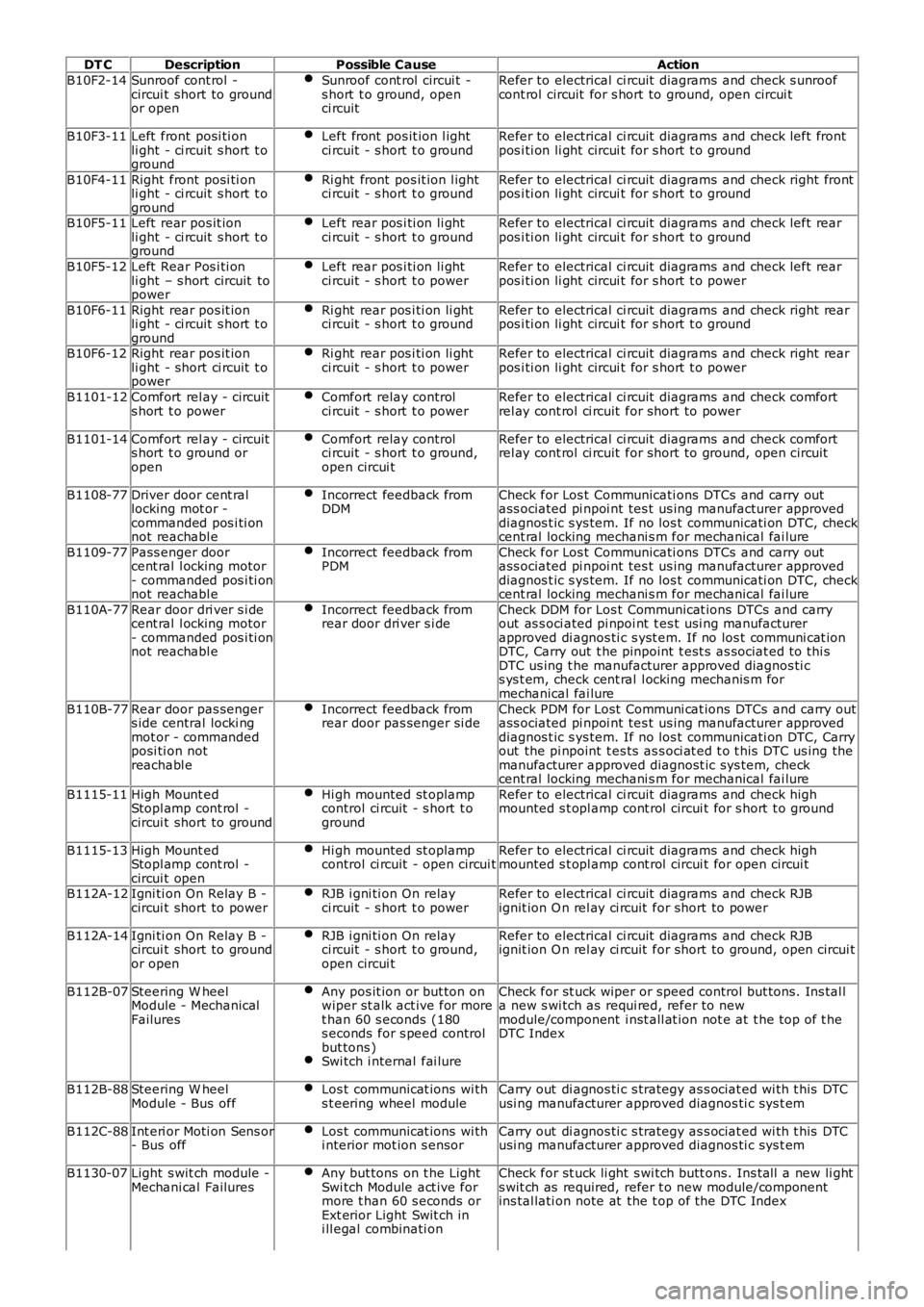
DT CDescriptionPossible CauseAction
B10F2-14Sunroof cont rol -circui t short to groundor open
Sunroof cont rol circui t -s hort t o ground, openci rcuit
Refer to electrical ci rcuit diagrams and check s unroofcont rol circuit for s hort to ground, open circui t
B10F3-11Left front posi ti onli ght - ci rcuit s hort t oground
Left front pos it ion l ightci rcuit - s hort t o groundRefer to electrical ci rcuit diagrams and check left frontpos i ti on li ght circui t for s hort t o ground
B10F4-11Right front posi ti onli ght - ci rcuit s hort t oground
Ri ght front pos it ion l ightci rcuit - s hort t o groundRefer to electrical ci rcuit diagrams and check right frontpos i ti on li ght circui t for s hort t o ground
B10F5-11Left rear pos it ionli ght - ci rcuit s hort t oground
Left rear pos i ti on li ghtci rcuit - s hort t o groundRefer to electrical ci rcuit diagrams and check left rearpos i ti on li ght circui t for s hort t o ground
B10F5-12Left Rear Pos i ti onli ght – s hort circuit topower
Left rear pos i ti on li ghtci rcuit - s hort t o powerRefer to electrical ci rcuit diagrams and check left rearpos i ti on li ght circui t for s hort t o power
B10F6-11Right rear pos it ionli ght - ci rcuit s hort t oground
Ri ght rear pos i ti on li ghtci rcuit - s hort t o groundRefer to electrical ci rcuit diagrams and check right rearpos i ti on li ght circui t for s hort t o ground
B10F6-12Right rear pos it ionli ght - short ci rcuit t opower
Ri ght rear pos i ti on li ghtci rcuit - s hort t o powerRefer to electrical ci rcuit diagrams and check right rearpos i ti on li ght circui t for s hort t o power
B1101-12Comfort rel ay - circuits hort t o powerComfort relay controlci rcuit - s hort t o powerRefer to electrical ci rcuit diagrams and check comfortrel ay cont rol ci rcuit for short to power
B1101-14Comfort rel ay - circuits hort t o ground oropen
Comfort relay controlci rcuit - s hort t o ground,open circui t
Refer to electrical ci rcuit diagrams and check comfortrel ay cont rol ci rcuit for short to ground, open circui t
B1108-77Driver door cent rallocking mot or -commanded pos i ti onnot reachabl e
Incorrect feedback fromDDMCheck for Los t Communicati ons DTCs and carry outass ociated pi npoi nt tes t us ing manufacturer approveddiagnos t ic s ys tem. If no los t communicati on DTC, checkcent ral locking mechani s m for mechanical fai lure
B1109-77Pass enger doorcent ral l ocking motor- commanded pos i ti onnot reachabl e
Incorrect feedback fromPDMCheck for Los t Communicati ons DTCs and carry outass ociated pi npoi nt tes t us ing manufacturer approveddiagnos t ic s ys tem. If no los t communicati on DTC, checkcent ral locking mechani s m for mechanical fai lure
B110A-77Rear door dri ver s i decent ral l ocking motor- commanded pos i ti onnot reachabl e
Incorrect feedback fromrear door dri ver s i deCheck DDM for Los t Communicat ions DTCs and carryout as s oci ated pi npoi nt t es t usi ng manufacturerapproved di agnos ti c s yst em. If no los t communi cat ionDTC, Carry out t he pinpoint t est s as sociat ed t o thi sDTC us ing t he manufacturer approved diagnos ti cs ys t em, check cent ral l ocking mechanis m formechanical fai lure
B110B-77Rear door pas sengers ide central locki ngmot or - commandedposi ti on notreachabl e
Incorrect feedback fromrear door pas senger si deCheck PDM for Lost Communi cat ions DTCs and carry outass ociated pi npoi nt tes t us ing manufacturer approveddiagnos t ic s ys tem. If no los t communicati on DTC, Carryout the pi npoint t es ts as s oci at ed t o t his DTC us ing themanufacturer approved diagnost ic sys tem, checkcent ral locking mechani s m for mechanical fai lure
B1115-11High Mount edStopl amp cont rol -circui t short to ground
Hi gh mounted st oplampcontrol ci rcuit - s hort t oground
Refer to electrical ci rcuit diagrams and check highmounted s t opl amp cont rol circui t for s hort t o ground
B1115-13High Mount edStopl amp cont rol -circui t open
Hi gh mounted st oplampcontrol ci rcuit - open circui tRefer to electrical ci rcuit diagrams and check highmounted s t opl amp cont rol circui t for open circui t
B112A-12Igni ti on On Relay B -circui t short to powerRJB i gni ti on On relayci rcuit - s hort t o powerRefer to electrical ci rcuit diagrams and check RJBignit ion O n rel ay ci rcuit for short to power
B112A-14Igni ti on On Relay B -circui t short to groundor open
RJB i gni ti on On relayci rcuit - s hort t o ground,open circui t
Refer to electrical ci rcuit diagrams and check RJBignit ion O n rel ay ci rcuit for short to ground, open circui t
B112B-07Steering W heelModule - MechanicalFailures
Any pos it ion or but ton onwiper st alk act ive for moret han 60 s econds (180s econds for s peed controlbut tons )Swi tch i nternal fai lure
Check for st uck wiper or speed control but tons . Ins tal la new s wi tch as requi red, refer to newmodule/component i nst all at ion not e at t he top of t heDTC Index
B112B-88Steering W heelModule - Bus offLos t communicat ions wi ths t eering wheel moduleCarry out di agnos ti c s trategy as s ociat ed wi th t his DTCusi ng manufacturer approved diagnos ti c sys t em
B112C-88Int eri or Moti on Sens or- Bus offLos t communicat ions wi thi nterior mot ion s ensorCarry out di agnos ti c s trategy as s ociat ed wi th t his DTCusi ng manufacturer approved diagnos ti c sys t em
B1130-07Light s wit ch module -Mechani cal FailuresAny but tons on t he LightSwi tch Module act ive formore t han 60 s econds orExt erior Light Swit ch ini ll egal combinati on
Check for st uck li ght s wi tch butt ons. Ins tall a new li ghts wit ch as required, refer t o new module/componentins tal lati on note at the t op of the DTC Index
Page 1791 of 3229
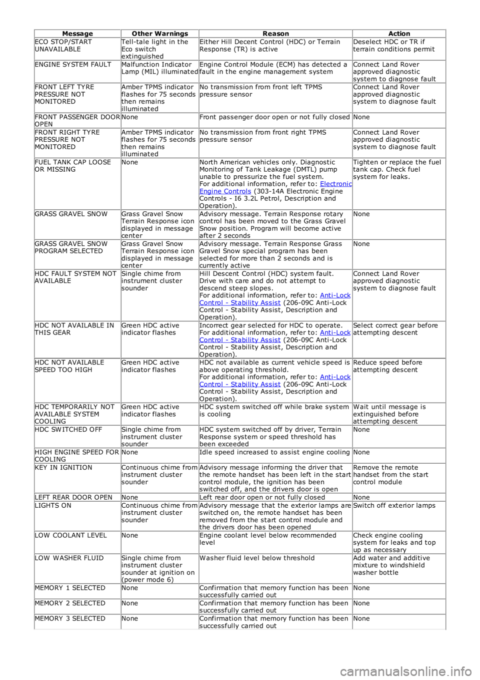
MessageO ther WarningsReasonAction
ECO STOP/STARTUNAVAILABLETel l-tal e li ght in t heEco swi tchext inguis hed
Eit her Hi ll Decent Control (HDC) or TerrainRespons e (TR) i s act iveDes elect HDC or TR i fterrain condit ions permi t
ENGINE SY STEM FAULTMalfunct ion Indi cat orLamp (MIL) il lumi nat edEngi ne Cont rol Module (ECM) has detected afault i n t he engi ne management s ys temConnect Land Roverapproved di agnos ti csys tem t o diagnos e faultFRONT LEFT TY REPRESSURE NOTMONITORED
Amber TPMS indicatorfl ashes for 75 secondsthen remainsil lumi nat ed
No t rans mis s ion from front left TPMSpres sure s ensorConnect Land Roverapproved di agnos ti csys tem t o diagnos e fault
FRONT PASSENGER DOOROPENNoneFront pas s enger door open or not fully cl osedNone
FRONT RIGHT TY REPRESSURE NOTMONITORED
Amber TPMS indicatorfl ashes for 75 secondsthen remainsil lumi nat ed
No t rans mis s ion from front ri ght TPMSpres sure s ensorConnect Land Roverapproved di agnos ti csys tem t o diagnos e fault
FUEL TANK CAP LOOSEOR MISSINGNoneNort h American vehi cl es onl y. Diagnos t icMonit oring of Tank Leakage (DMTL) pumpunabl e to pres surize t he fuel s yst em.For addit ional informati on, refer t o: Elect roni cEngi ne Cont rol s (303-14A Electroni c Engi neCont rol s - I6 3.2L Pet rol, Des cri pt ion andOperati on).
Ti ght en or repl ace t he fueltank cap. Check fuelsys tem for l eaks .
GRASS GRAVEL SNOWGras s Gravel SnowTerrai n Res pons e i condis played in mess agecent er
Advi sory mes s age. Terrain Res pons e rotarycont rol has been moved to the Grass GravelSnow posi ti on. Program will become acti veaft er 2 s econds
None
GRASS GRAVEL SNOWPROGRAM SELECTEDGras s Gravel SnowTerrai n Res pons e i condis played in mess agecent er
Advi sory mes s age. Terrain Res pons e Gras sGravel Snow special program has beens el ect ed for more t han 2 s econds and i scurrent ly acti ve
None
HDC FAULT SY STEM NOTAVAILABLESingle chime fromins trument cl ust ers ounder
Hil l Des cent Cont rol (HDC) sys tem faul t.Dri ve wit h care and do not at tempt t odes cend s teep s lopes .For addit ional informati on, refer t o: Ant i-LockCont rol - St abi li ty As s is t (206-09C Anti -LockCont rol - St abi li ty As s is t , Des cri pti on andOperati on).
Connect Land Roverapproved di agnos ti csys tem t o diagnos e fault
HDC NOT AVAILABLE INTHIS GEARGreen HDC act iveindicator flas hesIncorrect gear s el ect ed for HDC to operate.For addit ional informati on, refer t o: Ant i-LockCont rol - St abi li ty As s is t (206-09C Anti -LockCont rol - St abi li ty As s is t , Des cri pti on andOperati on).
Sel ect correct gear beforeat t empt ing des cent
HDC NOT AVAILABLESPEED TOO HIGHGreen HDC act iveindicator flas hesHDC not avai lable as current vehi cl e s peed isabove operat ing t hres hold.For addit ional informati on, refer t o: Ant i-LockCont rol - St abi li ty As s is t (206-09C Anti -LockCont rol - St abi li ty As s is t , Des cri pti on andOperati on).
Reduce s peed beforeat t empt ing des cent
HDC TEMPORARILY NOTAVAILABLE SY STEMCOOLING
Green HDC act iveindicator flas hesHDC s yst em swi tched off whi le brake s ys t emis cooli ngW ait unt il mes sage i sext inguis hed beforeat t empt ing des cent
HDC SW ITCHED O FFSingle chime fromins trument cl ust ers ounder
HDC s yst em swi tched off by driver, TerrainRespons e s ys t em or s peed thres hold hasbeen exceeded
None
HIGH ENGINE SPEED FORCOOLINGNoneIdl e s peed increased to as s is t engine cool ingNone
KEY IN IGNITIONCont inuous chi me fromins trument cl ust ers ounder
Advi sory mes s age informing the driver thatthe remot e hands et has been left i n t he s tartcont rol module, t he ignit ion has beens wit ched off, and t he dri vers door i s open
Remove t he remotehands et from t he s tartcontrol modul e
LEFT REAR DOOR O PENNoneLeft rear door open or not ful ly cl os edNone
LIGHTS ONCont inuous chi me fromins trument cl ust ers ounder
Advi sory mes s age that t he ext eri or l amps ares wit ched on, t he remot e hands et has beenremoved from the s t art control modul e andthe drivers door has been opened
Swi tch off ext eri or lamps
LOW COOLANT LEVELNoneEngi ne cool ant l evel below recommendedlevelCheck engine cool ingsys tem for l eaks and t opup as neces sary
LOW W ASHER FLUIDSingle chime fromins trument cl ust ers ounder at ignit ion on(power mode 6)
W as her flui d level bel ow t hres hol dAdd water and addi ti vemixt ure t o wi nds hiel dwas her bott le
MEMORY 1 SELECTEDNoneConfirmati on t hat memory funct ion has beens uccess ful ly carried outNone
MEMORY 2 SELECTEDNoneConfirmati on t hat memory funct ion has beens uccess ful ly carried outNone
MEMORY 3 SELECTEDNoneConfirmati on t hat memory funct ion has beens uccess ful ly carried outNone
Page 1920 of 3229
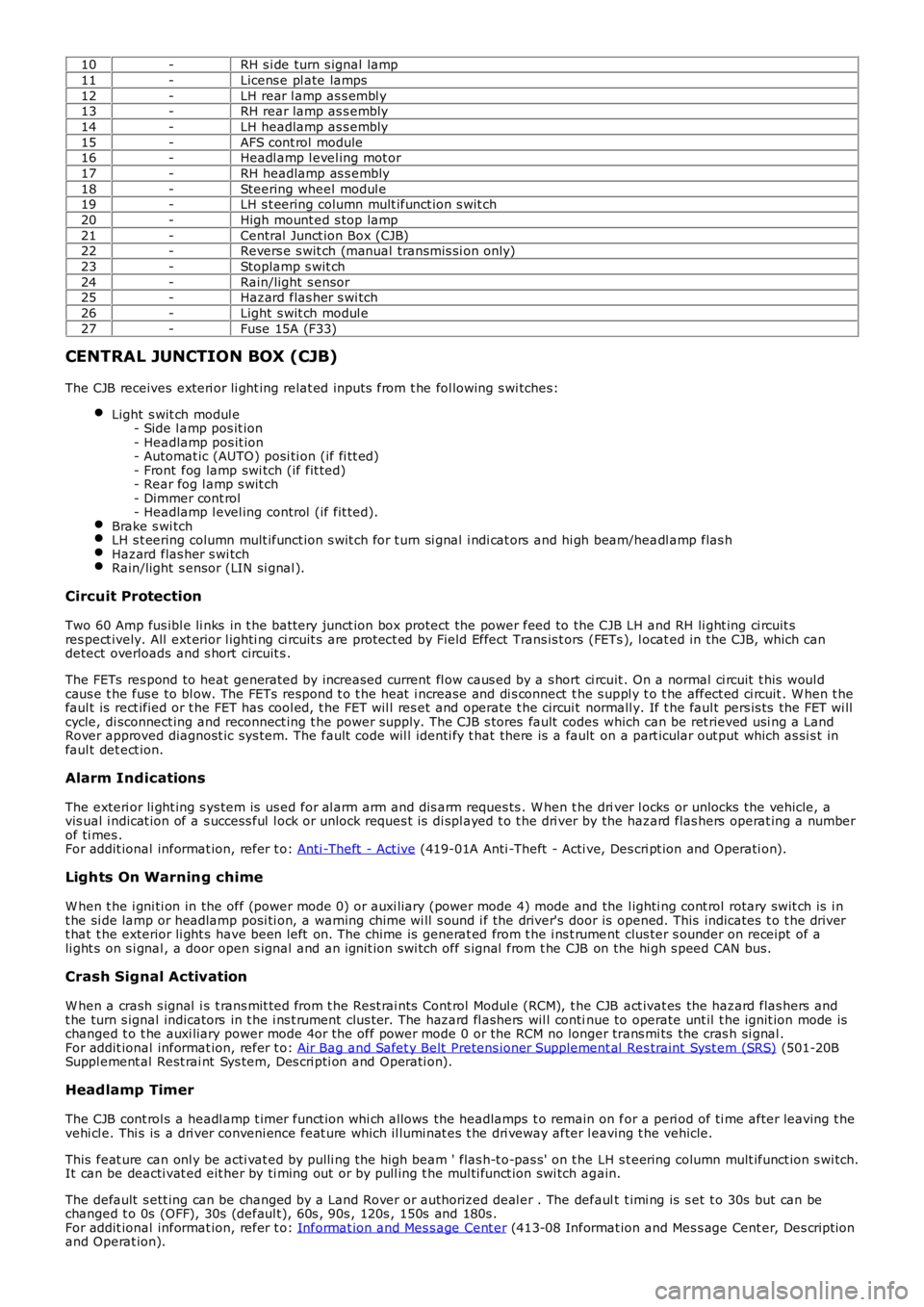
10-RH s i de turn s ignal lamp
11-Licens e pl ate lamps
12-LH rear l amp as s embl y13-RH rear lamp as s embly
14-LH headlamp as s embly
15-AFS cont rol module16-Headl amp l evel ing mot or
17-RH headlamp as s embly
18-Steering wheel modul e19-LH s t eering column mult ifunct ion s wit ch
20-High mount ed s top lamp
21-Central Junct ion Box (CJB)22-Revers e s wit ch (manual transmis si on only)
23-Stoplamp s wit ch
24-Rain/light s ensor25-Hazard flas her s wi tch
26-Light s wit ch modul e
27-Fuse 15A (F33)
CENTRAL JUNCTION BOX (CJB)
The CJB receives exteri or li ght ing relat ed inputs from t he fol lowing s wi tches:
Light s wit ch modul e- Side l amp pos it ion- Headlamp pos it ion- Automat ic (AUTO) posi ti on (if fi tt ed)- Front fog lamp swi tch (if fit ted)- Rear fog l amp s wit ch- Dimmer cont rol- Headlamp l evel ing control (if fit ted).Brake s wi tchLH s t eering column mult ifunct ion s wit ch for t urn si gnal i ndi cat ors and hi gh beam/headl amp flas hHazard flas her s wi tchRain/light s ensor (LIN si gnal ).
Circuit Protection
Two 60 Amp fus ibl e li nks in t he batt ery junct ion box protect the power feed to the CJB LH and RH li ght ing ci rcuit sres pect ively. All ext erior l ighti ng ci rcuit s are prot ect ed by Field Effect Trans is t ors (FETs ), l ocat ed in the CJB, which candetect overloads and s hort circuit s .
The FETs res pond to heat generated by increased current fl ow caus ed by a s hort ci rcuit . On a normal ci rcuit t his woul dcaus e t he fus e to bl ow. The FETs respond t o t he heat i ncrease and di s connect t he s uppl y t o t he affect ed ci rcuit . W hen t hefaul t is rect ified or t he FET has cool ed, t he FET wil l res et and operate t he circui t normall y. If t he faul t pers is ts the FET wi llcycle, di sconnect ing and reconnect ing t he power supply. The CJB s tores fault codes which can be ret rieved usi ng a LandRover approved diagnost ic sys tem. The fault code wil l identi fy t hat there is a fault on a part icular out put which as si s t infaul t det ect ion.
Alarm Indications
The exteri or li ght ing s ys tem is us ed for al arm arm and dis arm reques ts . W hen t he driver l ocks or unlocks the vehicle, avis ual i ndicat ion of a s uccess ful l ock or unlock reques t is di spl ayed t o t he dri ver by the hazard flas hers operat ing a numberof ti mes .For addit ional informat ion, refer t o: Anti -Theft - Act ive (419-01A Anti -Theft - Acti ve, Des cri pt ion and Operati on).
Lights On Warning chime
W hen t he i gni ti on in the off (power mode 0) or auxi liary (power mode 4) mode and the l ighti ng cont rol rotary swit ch is i nt he si de lamp or headlamp posi ti on, a warning chime wi ll s ound i f the driver's door is opened. This indicates t o t he dri vert hat t he exterior li ght s have been left on. The chime is generat ed from t he i ns t rument clus ter s ounder on receipt of ali ght s on s i gnal , a door open s ignal and an ignit ion swi tch off s ignal from t he CJB on the hi gh s peed CAN bus.
Crash Signal Activation
W hen a crash s ignal i s t rans mit ted from t he Rest rai nts Cont rol Modul e (RCM), t he CJB act ivat es the hazard flas hers andt he turn s ignal indicators in t he i ns t rument clus ter. The hazard fl ashers wil l continue to operate unt il t he ignit ion mode ischanged t o t he auxi liary power mode 4or the off power mode 0 or the RCM no longer trans mi ts the cras h si gnal .For addit ional informat ion, refer t o: Air Bag and Safet y Belt Pretens ioner Supplement al Res traint Syst em (SRS) (501-20BSuppl ement al Rest rai nt Sys tem, Des cri pti on and Operati on).
Headlamp Timer
The CJB cont rol s a headl amp t imer funct ion whi ch allows the headlamps t o remain on for a peri od of ti me after leaving t hevehi cl e. Thi s is a dri ver conveni ence feat ure which il lumi nat es t he dri veway after leaving t he vehicle.
This feat ure can onl y be acti vat ed by pulli ng t he high beam ' flas h-t o-pas s' on t he LH s t eering column mult ifunct ion s wi tch.It can be deacti vat ed eit her by ti ming out or by pull ing t he mul ti funct ion swi tch again.
The default s ett ing can be changed by a Land Rover or authorized deal er . The default t imi ng is s et t o 30s but can bechanged t o 0s (OFF), 30s (defaul t), 60s , 90s , 120s , 150s and 180s .For addit ional informat ion, refer t o: Informat ion and Mes s age Cent er (413-08 Informat ion and Mes s age Cent er, Des cript ionand Operat ion).
Page 1956 of 3229
Publi s hed: 11-May-2011
Interior Lighting - Interior Lighting
Diagnosi s and Tes ti ng
Principles of Operation
For a detail ed descripti on of the interior li ght ing sys tem, refer t o t he rel evant Des cript ion and Operat ion s ecti on in theworks hop manual .REFER to: Interior Lighti ng (417-02 Int erior Light ing, Descri pti on and Operat ion).
Inspection and Verification
CAUTION: Di agnos is by s ubs ti tut ion from a donor vehicle is NO T acceptabl e. Subs ti tut ion of cont rol modules doesnot guarant ee confirmat ion of a faul t, and may als o caus e addit ional fault s i n t he vehi cl e being t est ed and/or t he donorvehi cl e.
1. Verify t he cus t omer concern.1.
2. Vis ually ins pect for obvious s igns of mechani cal or electrical damage.2.
Visual InspectionMechanicalElectrical
BulbsFus es/rel ays (refer to electrical gui de)W iring harnes sCorrect engagement of elect rical connect orsLoos e or corroded connecti ons
3. If an obvious cause for an obs erved or report ed concern is found, correct t he caus e (if pos s ible) beforeproceeding t o t he next s t ep.3.
4. If t he caus e is not vis ually evi dent , check for Di agnos ti c Trouble Codes (DTCs) and refer t o t he DTC Index.4.
DTC Index
• NOTE: If the control modul e or a component i s s us pect and the vehicle remains under manufacturer warrant y, refer t o theW arranty Pol icy and Procedures manual (s ect ion B1.2), or determine i f any pri or approval programme is in operat ion, pri ort o the ins tall ati on of a new module/component.
• NOTE: Generic scan t ool s may not read the codes li st ed, or may read only fi ve digit codes . Mat ch the five di git s from t hes can tool to the firs t fi ve di git s of the seven digi t code l is ted to ident ify t he faul t (t he las t t wo digi ts gi ve ext rainformat ion read by the manufact urer-approved diagnost ic s ys tem).
• NOTE: W hen performing volt age or res is t ance t est s , always use a digi tal mult imeter (DMM) accurat e t o t hree deci malplaces and wit h a current cal ibrat ion cert ificate. W hen tes ti ng res i st ance, always take the res is tance of the DMM l eads i ntoaccount.
• NOTE: Check and recti fy bas ic faul ts before beginni ng diagnos t ic rout ines i nvol vi ng pinpoint t es t s.
• NOTE: If DTCs are recorded and, aft er performi ng the pi npoi nt tes ts , a fault is not present , an int ermi tt ent concern maybe t he caus e. Always check for loose connect ions and corroded terminals .
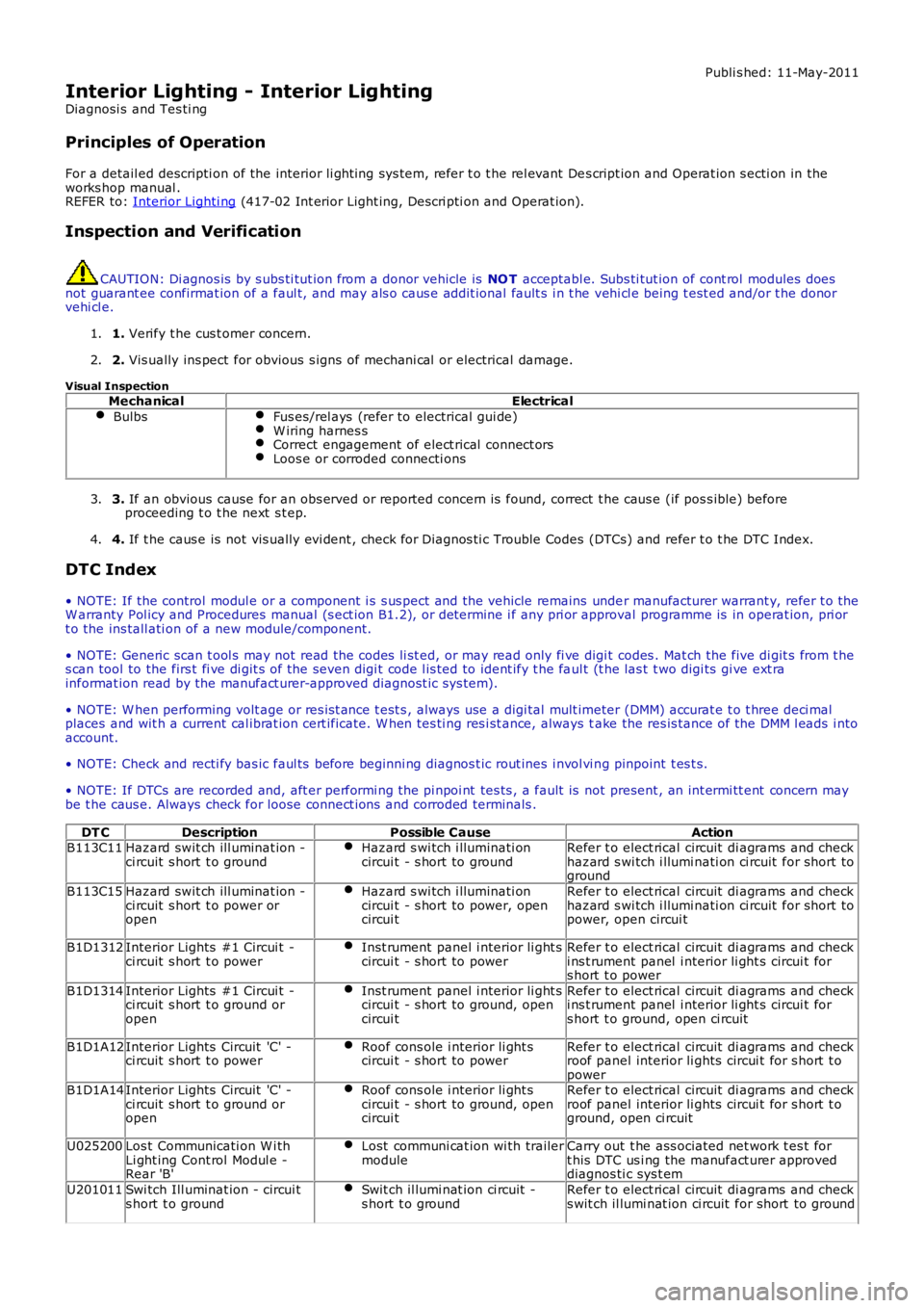
DT CDescriptionPossible CauseActionB113C11Hazard swit ch ill uminat ion -ci rcuit s hort t o groundHazard s wi tch i lluminati oncircui t - s hort to groundRefer t o elect rical circuit di agrams and checkhazard s wi tch i llumi nati on ci rcuit for short toground
B113C15Hazard swit ch ill uminat ion -ci rcuit s hort t o power oropen
Hazard s wi tch i lluminati oncircui t - s hort to power, opencircui t
Refer t o elect rical circuit di agrams and checkhazard s wi tch i llumi nati on ci rcuit for short topower, open circui t
B1D1312Interior Lights #1 Circui t -ci rcuit s hort t o powerInst rument panel i nterior li ght scircui t - s hort to powerRefer t o elect rical circuit di agrams and checki ns t rument panel i nterior li ght s circui t fors hort t o power
B1D1314Interior Lights #1 Circui t -ci rcuit s hort t o ground oropen
Inst rument panel i nterior li ght scircui t - s hort to ground, opencircui t
Refer t o elect rical circuit di agrams and checki ns t rument panel i nterior li ght s circui t fors hort t o ground, open ci rcuit
B1D1A12Interior Lights Circuit 'C' -ci rcuit s hort t o powerRoof cons ole i nterior li ght scircui t - s hort to powerRefer t o elect rical circuit di agrams and checkroof panel interior li ghts circui t for s hort t opowerB1D1A14Interior Lights Circuit 'C' -ci rcuit s hort t o ground oropen
Roof cons ole i nterior li ght scircui t - s hort to ground, opencircui t
Refer t o elect rical circuit di agrams and checkroof panel interior li ghts circui t for s hort t oground, open ci rcuit
U025200Los t Communicati on W i thLi ght ing Cont rol Modul e -Rear 'B'
Lost communi cat ion wi th trailermoduleCarry out t he ass ociated net work t es t fort his DTC us i ng the manufact urer approveddiagnos ti c sys t em
U201011Swi tch Ill uminat ion - circui ts hort t o groundSwit ch il lumi nat ion ci rcuit -s hort t o groundRefer t o elect rical circuit di agrams and checks wit ch il lumi nat ion ci rcuit for short to ground
Page 2727 of 3229
7
Quick start
R
Quick startQUICK START
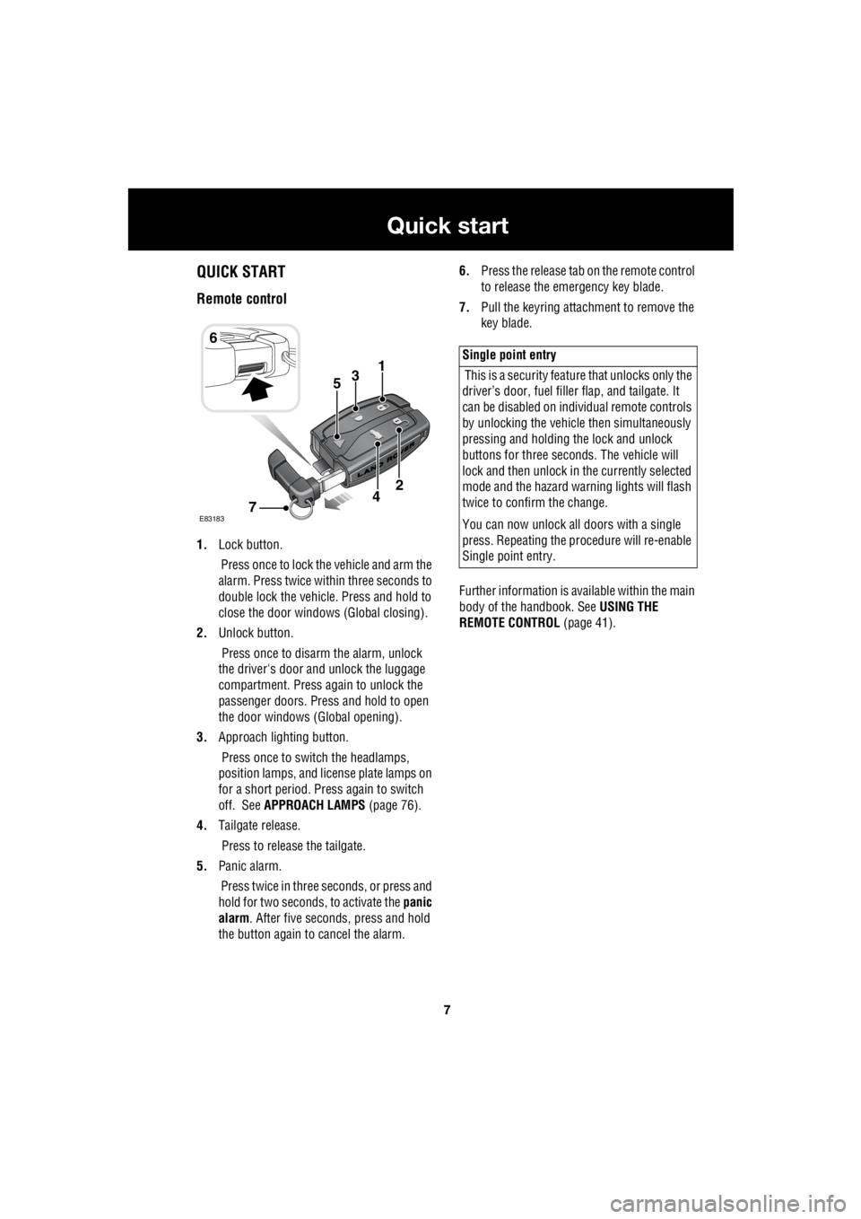
Remote control
1. Lock button.
Press once to lock the vehicle and arm the
alarm. Press twice within three seconds to
double lock the vehicle. Press and hold to
close the door windows (Global closing).
2. Unlock button.
Press once to disarm the alarm, unlock
the driver's door and unlock the luggage
compartment. Press again to unlock the
passenger doors. Press and hold to open
the door windows (Global opening).
3. Approach lighting button.
Press once to switch the headlamps,
position lamps, and license plate lamps on
for a short period. Press again to switch
off. See APPROACH LAMPS (page 76).
4. Tailgate release.
Press to release the tailgate.
5. Panic alarm.
Press twice in three seconds, or press and
hold for two seconds, to activate the panic
alarm . After five seconds, press and hold
the button again to cancel the alarm. 6.
Press the release tab on the remote control
to release the emergency key blade.
7. Pull the keyring attachment to remove the
key blade.
Further information is available within the main
body of the handbook. See USING THE
REMOTE CONTROL (page 41).
6
31
E83183
2
74
5
Single point entry
This is a security feature that unlocks only the
driver’s door, fuel fille r flap, and tailgate. It
can be disabled on indi vidual remote controls
by unlocking the vehicle then simultaneously
pressing and holding th e lock and unlock
buttons for three sec onds. The vehicle will
lock and then unlock in the currently selected
mode and the hazard wa rning lights will flash
twice to confirm the change.
You can now unlock all doors with a single
press. Repeating the pr ocedure will re-enable
Single point entry.
Page 2761 of 3229
41
Keys and remote controls
R
USING THE REMOTE CONTROL
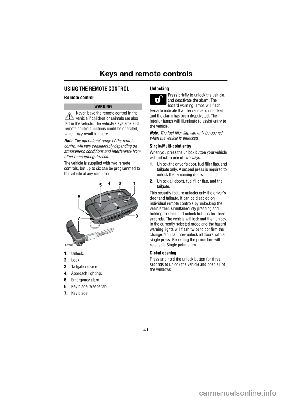
Remote control
Note: The operational range of the remote
control will vary considerably depending on
atmospheric conditions and interference from
other transmitting devices.
The vehicle is supplied with two remote
controls, but up to six can be programmed to
the vehicle at any one time.
1. Unlock.
2. Lock.
3. Tailgate release.
4. Approach lighting.
5. Emergency alarm.
6. Key blade release tab.
7. Key blade.
Unlocking
Press briefly to unlock the vehicle,
and deactivate the alarm. The
hazard warning lamps will flash
twice to indicate that the vehicle is unlocked
and the alarm has been deactivated. The
interior lamps will illuminate to assist entry to
the vehicle.
Note: The fuel filler flap can only be opened
when the vehicle is unlocked.
Single/Multi- point entry
When you press the unlock button your vehicle
will unlock in one of two ways:
1. Unlock the driver's door, fuel filler flap, and
tailgate only. A second press is required to
unlock the remaining doors.
2. Unlock all doors, fuel filler flap, and the
tailgate.
This security feature unlocks only the driver’s
door and tailgate. It can be disabled on
individual remote controls by unlocking the
vehicle then simultaneously pressing and
holding the lock and unlock buttons for three
seconds. The vehicle will lock and then unlock
in the currently selected mode and the hazard
warning lights will flas h twice to confirm the
change. You can now unlock all doors with a
single press. Repeating the procedure will
re-enable Single point entry.
Global opening
Press and hold the unlock button for three
seconds to unlock the ve hicle and open all of
the windows.
WARNING
Never leave the remote control in the
vehicle if children or animals are also
left in the vehicle. The vehicle's systems and
remote control functions could be operated,
which may result in injury.
2
E80909
451
3
6
7
Page 2765 of 3229
45
Alarm
R
AlarmARMING THE ALARM
The engine is automatically
immobilised when the remote
control is removed from the starter
control unit. The alarm system is automatically
armed when the remote lock button is pressed.
The hazard lamps will flash to indicate that the
alarm is armed.
Full alarm
To set full alarm protection ensure that all the
windows and the sunroof are closed. Then
press the lock button twice within three
seconds. The hazard warn ing lights will flash
twice to confirm the alarm state.
Once fully armed the alarm will sound if :-
• the bonnet, tailgate, or a door are opened.
• movement is detected within the vehicle
interior.
• a window, front or rear windscreen, or
sunroof glass are broken.
• the vehicle is raised or tilted.
• the vehicle battery is disconnected.
• an attempt is made to disconnect the alarm
siren.
Note: If the alarm is armed and a window or the
sunroof are left open the alarm will sound due
to movement of air currents.
Partial alarm
To set partial alarm protection, briefly press the
lock button once. The hazard warning lights
will flash once to confirm the alarm state.
Once partially armed the alarm will sound if :-
• the bonnet, tailgate, or a door are opened.
• the vehicle battery is disconnected.
• an attempt is made to disconnect the alarm
siren. Note:
This setting should be used in
circumstances such as travelling on a ferry,
when pets are to be left in the vehicle, when a
window must be left open etc
Alarm indicator
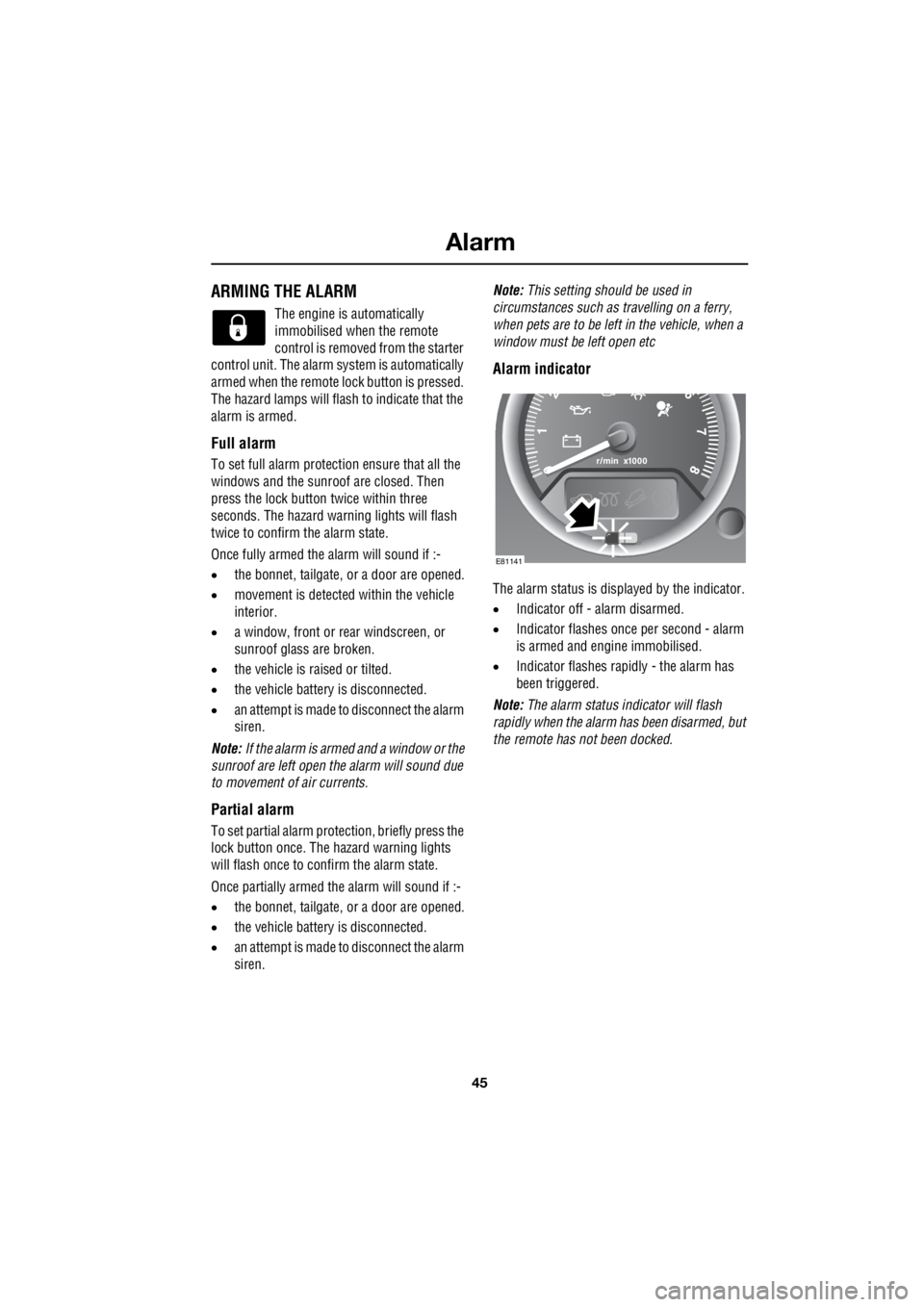
The alarm status is disp layed by the indicator.
• Indicator off - alarm disarmed.
• Indicator flashes once per second - alarm
is armed and engine immobilised.
• Indicator flashes rapidly - the alarm has
been triggered.
Note: The alarm status in dicator will flash
rapidly when the alarm has been disarmed, but
the remote has not been docked.
E81141
Page 2796 of 3229
Lighting
76
L
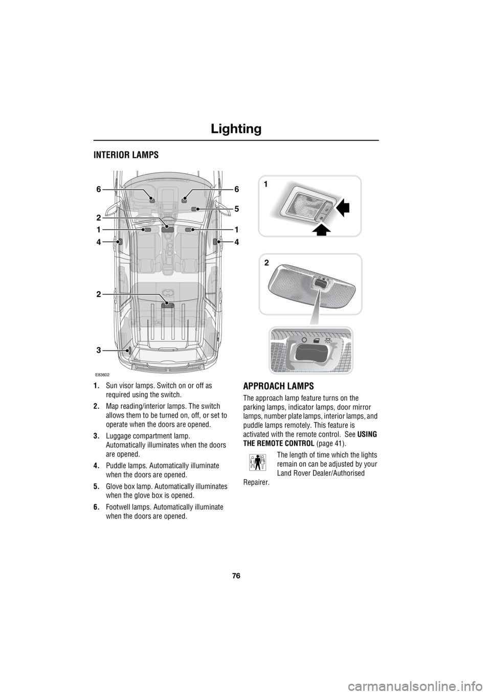
INTERIOR LAMPS
1. Sun visor lamps. Sw itch on or off as
required using the switch.
2. Map reading/interior lamps. The switch
allows them to be turn ed on, off, or set to
operate when the doors are opened.
3. Luggage compartment lamp.
Automatically illuminates when the doors
are opened.
4. Puddle lamps. Automatically illuminate
when the doors are opened.
5. Glove box lamp. Auto matically illuminates
when the glove box is opened.
6. Footwell lamps. Auto matically illuminate
when the doors are opened.APPROACH LAMPS
The approach lamp feature turns on the
parking lamps, indica tor lamps, door mirror
lamps, number plate lamps, interior lamps, and
puddle lamps remotely . This feature is
activated with the remote control. See USING
THE REMOTE CONTROL (page 41).
The length of time which the lights
remain on can be adjusted by your
Land Rover Dealer/Authorised
Repairer.
3
2
4
1
2
6
4
1
5
61
2
E83602