2006 LAND ROVER FRELANDER 2 radiator
[x] Cancel search: radiatorPage 181 of 3229
Air Filtering
CAUTION: When vehicles are operating under arduous conditions, the following service item must be carried outevery 12 months or 15,000 miles (24,000 km).
Replace the ai r fi lt er el ement.For addit ional informat ion, refer t o: Air Cl eaner (303-12A Int ake Ai r Dis t ri but ion and Fi lt ering - I6 3.2L Petrol ,Removal and Inst all ati on).
Accessory Drive Belt
CAUTION: When vehicles are operating under arduous conditions, the following service item must be carried outevery 5 years or 75,000 miles (120,000 km).
Replace the access ory drive bel t.For addit ional informat ion, refer t o: Acces sory Drive Belt (303-05A Acces s ory Drive - I6 3.2L Pet rol , Removal andIns t allat ion).
Radiator and Cooling Fan
CAUTION: When vehicles are operating under arduous conditions, the following item must be carried out.
Vis uall y check radi at or for external obs truct ions , check cool ing fan blades for damage.
Continuous Use In Severe Off-Road Conditions
CAUTION: After 50 miles (80 km) continuous use in severe off-road conditions i.e. w ading, deep mud andabrasive grit/slurry, the following items must be cleaned and inspected.
The parking brake.The acces sory dri ve belt .
Vehicles used in dusty or field conditions or d eep wading:
More frequent att enti on to the ai r cl eaner wi ll be requi red.
Additional Items That May Require Attention
1. Every 6 years: It i s recommended t hat al l brake fl uid hydrauli c s eal s are replaced.
• NOTE: This i s in addi ti on to the maintenance requirement that fl exi ble brake hos es MUST be replaced at thi s s erviceint erval.
Page 192 of 3229
Ins pect rear pads for wear.
Check brake cal ipers for s igns of fl ui d l eaks .
Check brake dis cs for condi ti on.
Check al l brake boos t er and brake s ys t em pipes and hos es for condi ti on, chafi ng and
leaks.Clean road wheel hub s pigot s and appl y greas e, Land Rover Part Number RY L 105020 t o
t he wheel mat ing surface
of each s pigot . Brake Fluid Replacement
CAUTION:
When vehicles are operating under arduous conditions, the following service item mus t be carried out
every 2 Years or 30,000 miles (48,000 km).
Replace brake fluid. Road Wheel Speed Sensors
CAUTION:
When vehicles are operating under arduous conditions, the following service item mus t be carried out
every 3 months or 3,750 miles (6,000 km).
Ins pect the road wheel s peed s ens or harness es for damage. Engine Oil and Filter
• CAUTIO NS:
When vehicles are operating under arduous conditions, the following service item mus t be carried out every 3
months or 3,750 miles (6,000 km).
Vehicles operating on high sulphur content fuel - above 0.7%, the oil and filter cha nge period MUST NOT
exceed 3 months or 3,750 miles (6,000 km).
Vehicles operating on moderate sulphur content fuel - 0.3 to 0.7%, the oil and filte r change period MUST NOT
exceed 6 months or 7,500 miles (12,000 km).
Renew engi ne oil and fil ter. Air Filtering
CAUTION:
When vehicles are operating under arduous conditions, the following service item mus t be carried out
every 12 months or 15,000 miles (24,000 km).
Replace the ai r fi lt er el ement.
For addit ional informat ion, refer t o: Air Cl eaner (303-12A Int ake Ai r Dis t ri but ion and Fi lt ering - I6 3.2L Petrol ,
Removal and Inst all ati on). Accessory Drive Belt
CAUTION:
When vehicles are operating under arduous conditions, the following service item mus t be carried out
every 5 years or 75,000 miles (120,000 km).
Replace the access ory drive bel t. For addi ti onal informat ion, refer to: Acces s ory Drive Belt (303-05A Acces s ory Drive
- I6 3.2L Pet rol, Removal and Ins tal lat ion). Camshaft Timing Belt, Tensioner and Pulley
CAUTION:
When vehicles are operating under arduous conditions, the following service item mus t be carried out
every 4 years or 60,000 miles (96,000 km).
Replace the cams haft t iming belt , tens ioner and pul ley.
For addit ional informat ion, refer t o: Timi ng Belt (303-01B Engi ne - TD4 2.2L Dies el, Removal and Inst all ati on).
Radiator/Charge Air Cooler and Cooling Fan
CAUTION:
When vehicles are operating under arduous conditions, the following items must be ca rried out.
Vis uall y check t he radiat or/charge air cool er for ext ernal obst ruct ions, check cooli ng fan bl ades for damage.Remove any debris from t he charge air cool er us i ng a l ow pres s ure hos e.
Continuous Use In Severe Off-Road Conditions
CAUTION:
After 50 miles (80 km) continuous use in severe off-road conditions i.e. w ading, dee p mud and
abrasive grit/slurry, the following items must be cleaned and inspected.
Page 542 of 3229
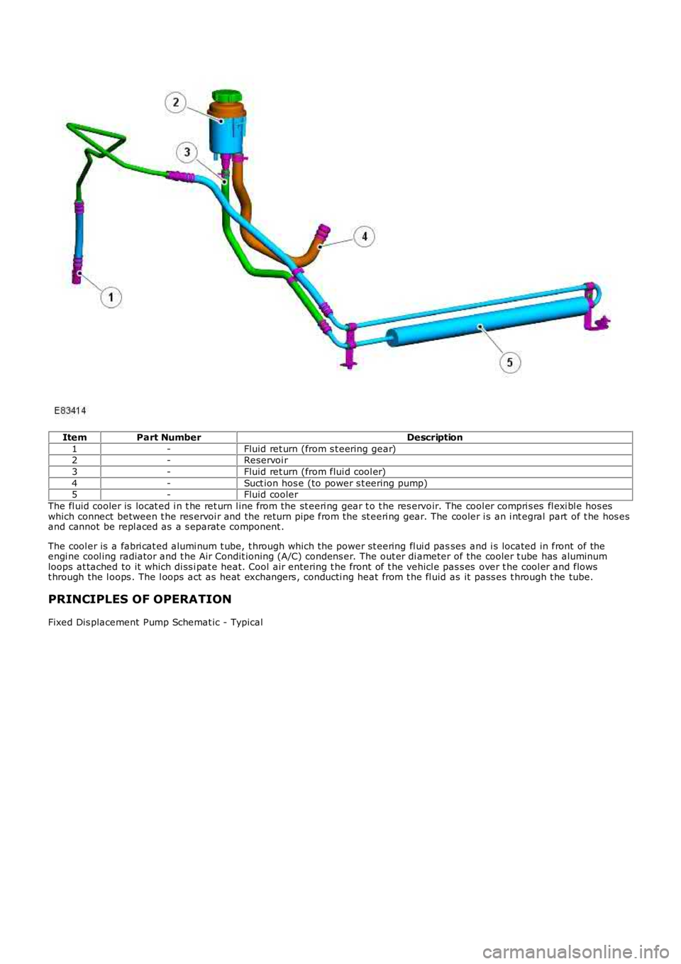
ItemPart NumberDescription
1-Fluid ret urn (from s t eering gear)2-Reservoi r
3-Fluid ret urn (from flui d cool er)
4-Suct ion hos e (to power s t eering pump)5-Fluid cooler
The fl uid cooler is locat ed i n t he ret urn l ine from the st eeri ng gear t o t he res ervoir. The cool er compri s es fl exi bl e hos eswhich connect between t he res ervoi r and the return pipe from the st eeri ng gear. The cooler i s an i nt egral part of t he hos esand cannot be repl aced as a s eparat e component .
The cool er is a fabri cat ed alumi num t ube, t hrough which t he power st eering fl ui d passes and i s located in front of theengi ne cool ing radiator and t he Air Condit ioning (A/C) condens er. The out er di ameter of the cooler t ube has aluminumloops at tached to it which di ss i pat e heat. Cool air entering t he front of t he vehicle pas s es over t he cool er and flowst hrough the l oops . The l oops act as heat exchangers , conducti ng heat from t he fl uid as it pass es t hrough t he tube.
PRINCIPLES OF OPERATION
Fixed Dis placement Pump Schemat ic - Typical
Page 911 of 3229
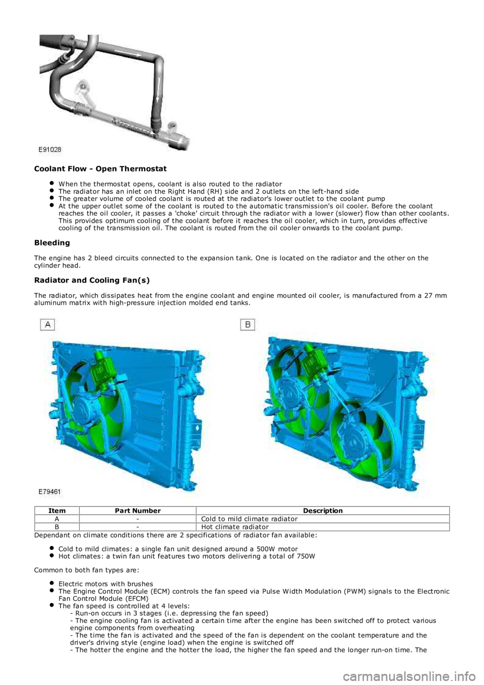
Coolant Flow - Open Thermostat
W hen t he t hermos tat opens, coolant is al so rout ed to the radiatorThe radi at or has an inl et on the Ri ght Hand (RH) s ide and 2 out let s on t he left-hand si deThe great er volume of cooled coolant is routed at the radi ator's l ower out let t o the coolant pumpAt t he upper outl et some of the coolant is routed t o t he automat ic t rans mi ss i on's oil cool er. Before t he coolantreaches the oi l cooler, it pas ses a 'choke' circuit t hrough t he radi at or wit h a lower (s lower) fl ow t han other cool ant s .This provi des opt imum cool ing of t he cool ant before i t reaches the oi l cooler, whi ch in turn, provi des effect ivecool ing of t he transmis s ion oil . The cool ant i s rout ed from t he oil cooler onwards to t he cool ant pump.
Bleeding
The engi ne has 2 bl eed ci rcuit s connected t o t he expans ion t ank. One is l ocat ed on the radiat or and the ot her on thecyl inder head.
Radiator and Cooling Fan(s)
The radi at or, whi ch di s si pat es heat from t he engine cool ant and engi ne mount ed oil cooler, i s manufactured from a 27 mmalumi num mat ri x wit h hi gh-pres s ure i nject ion molded end t anks .
ItemPart NumberDescription
A-Col d t o mi ld cli mat e radiat orB-Hot cl imat e radi at or
Dependant on cli mate condit ions t here are 2 s peci fi cat ions of radiat or fan avail abl e:
Cold t o mild cl imat es : a s ingle fan unit des igned around a 500W mot orHot climat es : a t win fan unit feat ures t wo motors del iveri ng a t otal of 750W
Common t o bot h fan types are:
Electric mot ors wit h brus hesThe Engi ne Control Module (ECM) controls t he fan speed via Pul s e W i dth Modulat ion (PW M) s i gnal s to the El ect ronicFan Cont rol Module (EFCM)The fan speed i s cont rol led at 4 l evel s:- Run-on occurs i n 3 s t ages (i.e. depres s ing the fan s peed)- The engine cool ing fan i s act ivated a cert ai n t ime aft er t he engine has been s wit ched off to prot ect vari ousengi ne component s from overheati ng- The t ime the fan is act ivated and the s peed of the fan i s dependent on the coolant t emperature and thedri ver's driving s t yle (engi ne load) when t he engi ne is swi tched off- The hott er the engine and the hot ter t he load, the hi gher t he fan speed and t he longer run-on ti me. The
Page 916 of 3229
If the pres s ure drops, check the complet e cool ing s ys tem for l eaks . Als o refer to engi ne s ys t em checks i f aleak cannot be locat ed in the cooli ng s ys t em. Correct any leaks found and recheck t he s ys t em.
7. Release the s ys tem pres s ure and remove the press ure tes t equipment. Check the coolant level. Replenis h asnecess ary wit h t he correct cool ant s olut ion.REFER t o: Specificati ons (303-03A Engine Cooli ng - I6 3.2L Pet rol, Specifi cat ions ).
7.
8. Check t he radi at or overfl ow hos e for any obs truct ions which may block the flow of coolant eit her to or from t hecoolant expans ion t ank.8.
9. Conduct the coolant expans ion t ank pres s ure cap pres s ure t es t in t his secti on.9.
Coolant Expansion Tank Pressure Cap Pressure Test
W ARNING: Never, under any ci rcums tances, remove the coolant expans ion tank pres s ure cap whi le t he engine i soperati ng. To avoid havi ng s caldi ng hot water or s team bl ow out of the cooli ng s ys t em, use ext reme care when removi ngt he coolant expans ion tank pres s ure cap from a hot cool ing s ys tem. W ai t unti l the engine has cooled, then wrap a t hickcloth around t he coolant expans ion tank pres s ure cap and t urn it s lowl y unt il t he pres s ure begins t o releas e, s t ep backwhil e t he pres sure i s rel eas ed from the s ys tem. W hen certai n all t he pres s ure has been rel eas ed (s ti ll wit h a cl oth) t urnand remove t he coolant expans ion t ank pres sure cap. Fail ure t o follow thes e i ns t ructi ons may res ult i n damage t o t hecool ing s ys tem, engine and/or cause pers onal injury.
1. Remove the expansi on tank press ure cap from t he cool ant expans i on tank.1.
2. Us e water t o clean cap in area of rubber s eal and vacuum rel ief valve. Fol lowing manufact urers ins truct ions ,i nst all t he cool ant expans i on tank pres s ure cap t o t he pres s ure t es ter.2.
• NOTE: If the press ure tes ter i s pres s uris ed t oo quickly, an erroneous pres s ure readi ng may resul t.
3. Slowly pres suris e t he s ys t em unt il the pres sure gauge reading s t ops i ncreasi ng, and not e highest press urereadi ng obtained.
3.
4. Release pres sure and repeat Step 3 at leas t twi ce to make s ure t he pres s ure t es t reading i s repeatable andwi thi n s peci ficat ion.4.
5. If t he pres s ure t es t gauge readi ngs are not wi thin s pecificati on, i nst all a new coolant expans ion tank pres s urecap.5.
Thermostat Test
Remove the thermos t atREFER to: Thermos t at (303-03A Engine Cooli ng - I6 3.2L Pet rol, Removal and Ins tal lat ion).Ins pect for vis ible damage, note it s openi ng t emperature and immers e i t in wat er. Heat t he water unti l thi s temperat ure isreached. The t hermos tat s hould begin to open. If i t does not begin to open, ins t al l a new t hermos tat .REFER to: Thermos t at (303-03A Engine Cooli ng - I6 3.2L Pet rol, Removal and Ins tal lat ion).If thermos t at begi ns to open, cont inue t o heat the wat er unt il t he t hermos tat fully opens , 5.8 mm (0.2 in) or more off t hes eat . If it does not full y open, i nst all a new thermos t at.REFER to: Thermos t at (303-03A Engine Cooli ng - I6 3.2L Pet rol, Removal and Ins tal lat ion).
Radiator Leak Test - Removed from the Vehicle
CAUTION: Do not l eak tes t an alumi nium radiat or i n t he s ame wat er t hat is us ed t o leak t es t copper/bras s radiat ors .Flux and caust ic cl eaners may be pres ent in the t est wat er which wi ll corrode al umini um. If a separat e t ank is notavai lable, drai n and rins e the tes t tank before t est ing an alumini um radi ator.
Clean t he radi at or before leak t es t ing t o prevent cont aminat ion of t he tes t t ank. Leak tes t t he radiat or in clean wat er wit h138 kPa (20 ps i ) air pres s ure.
Page 924 of 3229
Publi s hed: 11-May-2011
Engine Cooling - I6 3.2L Petrol - Radiator
Removal and Inst all ati on
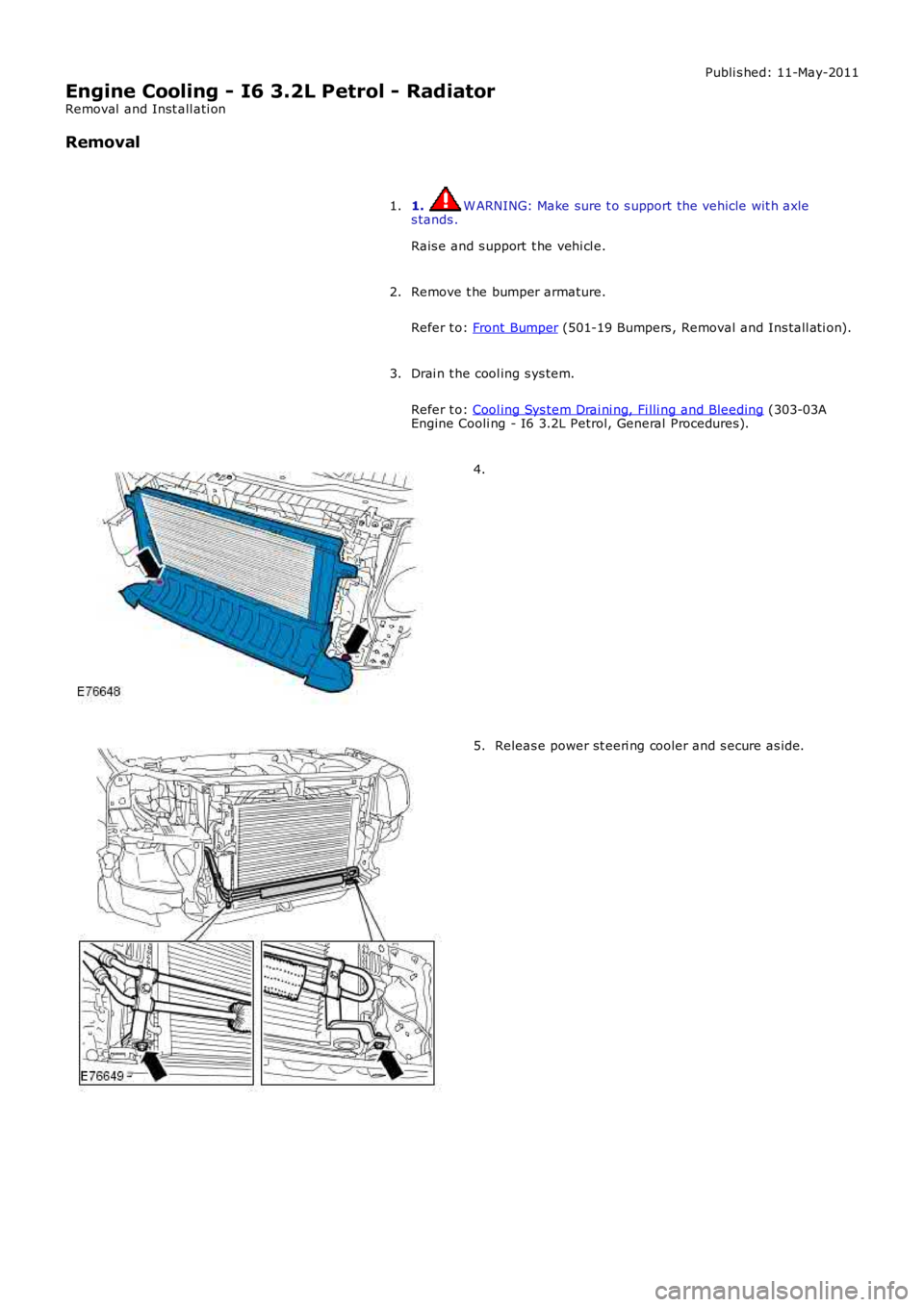
Removal
1. W ARNING: Make sure t o s upport the vehicle wit h axles tands .
Rais e and s upport t he vehi cl e.
1.
Remove t he bumper armature.
Refer t o: Front Bumper (501-19 Bumpers , Removal and Ins tall ati on).
2.
Drai n t he cool ing s ys tem.
Refer t o: Cool ing Sys tem Drai ni ng, Fi lli ng and Bleeding (303-03AEngine Cooli ng - I6 3.2L Petrol, General Procedures).
3.
4.
Releas e power st eeri ng cooler and s ecure as ide.5.
Page 937 of 3229
Publi s hed: 11-May-2011
Engine Cooling - TD4 2.2L Diesel -
Lubricants, Fluids, Sealers and AdhesivesItemSpecification
Anti -freezeTexaco Ext ended Li fe Coolant (XLC) or any glycol bas ed anti -freezecontaini ng no met hanol wit h only Organic Acid Technology (O AT) corrosi oni nhi bit ors
Anti -freeze concentrati on - W i ll provi de frostprot ect ion to -40°C (-40°F)50%
Speci fi c gravit y of cool ant at 20°C (68°F), t oprot ect agains t fros t down to -40°C (-40°F)1.068
Amount of anti-freeze to use for 50%concentration:4.25 li ters
C apacitiesItemCapacity (liters/pints/US quarts)
Cooli ng sys t em capacit y8.5/15.0/9.0
General Specification
ItemSpecificationCoolant pump21.5 li ter/mi n : 2.8 bar
Cooli ng fan750W /600W
Cooli ng sys t em t ypePress uri s ed, t hermos tat icall y cont roll ed wi th remote header t ankExpans ion tankSeeber wit h int egrated level s ensor
Pres s ure cap rati ng145 kPa (21lb/i n²)
Radiat orVal eo 28mm core wit h i nt egrat ed drain cock and repl aceable l ower pi nThermos t atW ax element
St arts to open83°C (181°F)
Full y open91°C (200°C)
Torque Specifications
DescriptionNmlb-ftA/C condens er t o radiator107
Automat ic trans mi ss i on fl uid cooler66
Coolant manifold t o t hermos tat hous ing pipe.86Coolant expans ion t ank bol t107
Coolant pump bolt s1713
Cyli nder block s ealing pl ug4231Radiat or bolt s65
Radiat or drain pl ug76
Thermos t at hous ing bolt s86W iri ng harnes s s upport bracket .86
Page 941 of 3229
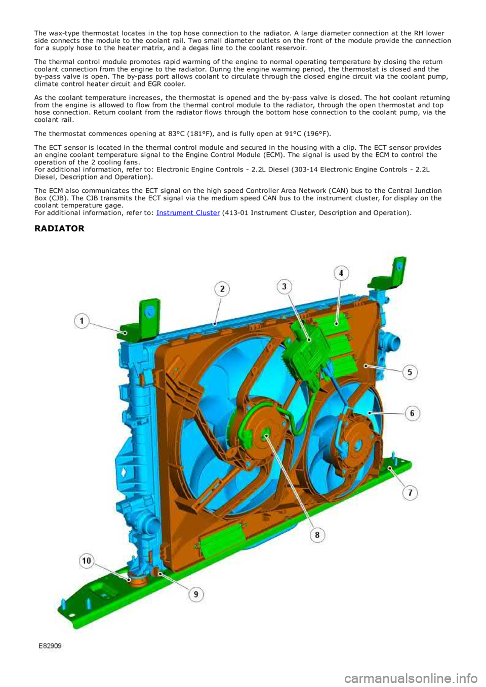
The wax-t ype thermost at locates i n t he top hos e connecti on t o t he radiat or. A l arge di ameter connecti on at the RH lowers ide connect s the modul e t o t he coolant rail. Two smal l diamet er out lets on the front of t he module provi de t he connect ionfor a supply hos e t o t he heat er mat rix, and a degas l ine t o t he cool ant reservoi r.
The t hermal cont rol module promotes rapi d warming of t he engine t o normal operat ing t emperature by clos ing t he returncool ant connect ion from the engi ne to the radiator. During the engine warmi ng period, t he thermost at is cl os ed and t heby-pas s val ve is open. The by-pass port all ows cool ant t o circul ate t hrough t he closed engi ne circuit vi a t he coolant pump,climate control heat er ci rcuit and EGR cooler.
As t he cool ant t emperat ure i ncreas es , the t hermos t at is opened and the by-pas s valve i s clos ed. The hot cool ant ret urningfrom the engine i s all owed to fl ow from the t hermal cont rol module to the radiator, through the open t hermos tat and t ophose connect ion. Return cool ant from t he radiat or fl ows through the bot tom hos e connect ion t o t he cool ant pump, via thecool ant rail .
The t hermos tat commences opening at 83°C (181°F), and i s ful ly open at 91°C (196°F).
The ECT s ens or is locat ed i n t he thermal control modul e and s ecured in the hous ing wi th a clip. The ECT s ens or provi desan engine coolant temperat ure si gnal t o t he Engi ne Control Module (ECM). The si gnal i s us ed by the ECM to cont rol t heoperati on of the 2 cool ing fans .For addit ional informat ion, refer t o: Electroni c Engi ne Controls - 2.2L Dies el (303-14 El ect ronic Engine Cont rols - 2.2LDies el, Des cript ion and Operat ion).
The ECM al so communi cat es the ECT si gnal on t he high speed Controll er Area Network (CAN) bus t o t he Central Junct ionBox (CJB). The CJB t rans mi ts t he ECT s ignal via t he medium s peed CAN bus to the ins trument cl us t er, for di spl ay on thecool ant t emperat ure gage.For addit ional informat ion, refer t o: Ins t rument Clus ter (413-01 Inst rument Cl us t er, Des cript ion and Operat ion).
RADIATOR