2006 LAND ROVER FRELANDER 2 change wheel
[x] Cancel search: change wheelPage 190 of 3229
Ensure that the steering wheel is in the straight ahead position, do not turn the st eering w heel prior to checking the
fluid level.
Check t hat the flui d level is t o t he mi d-way mark between the MAX and MIN marks on t he fluid res ervoir, t op-up i f
neces s ary. Clean t he area around the res ervoi r fi ll er cap, remove cap.
CAUTION:
Do not fill reservoir above the MAX mark.
If necess ary, t op-up us ing t he recommended fluid to the mid-way mark on the reservoi r.
For addit ional informat ion, refer t o: Specificati ons (211-02 Power St eering, Specificati ons).
Ins t all the res ervoir fill er cap.
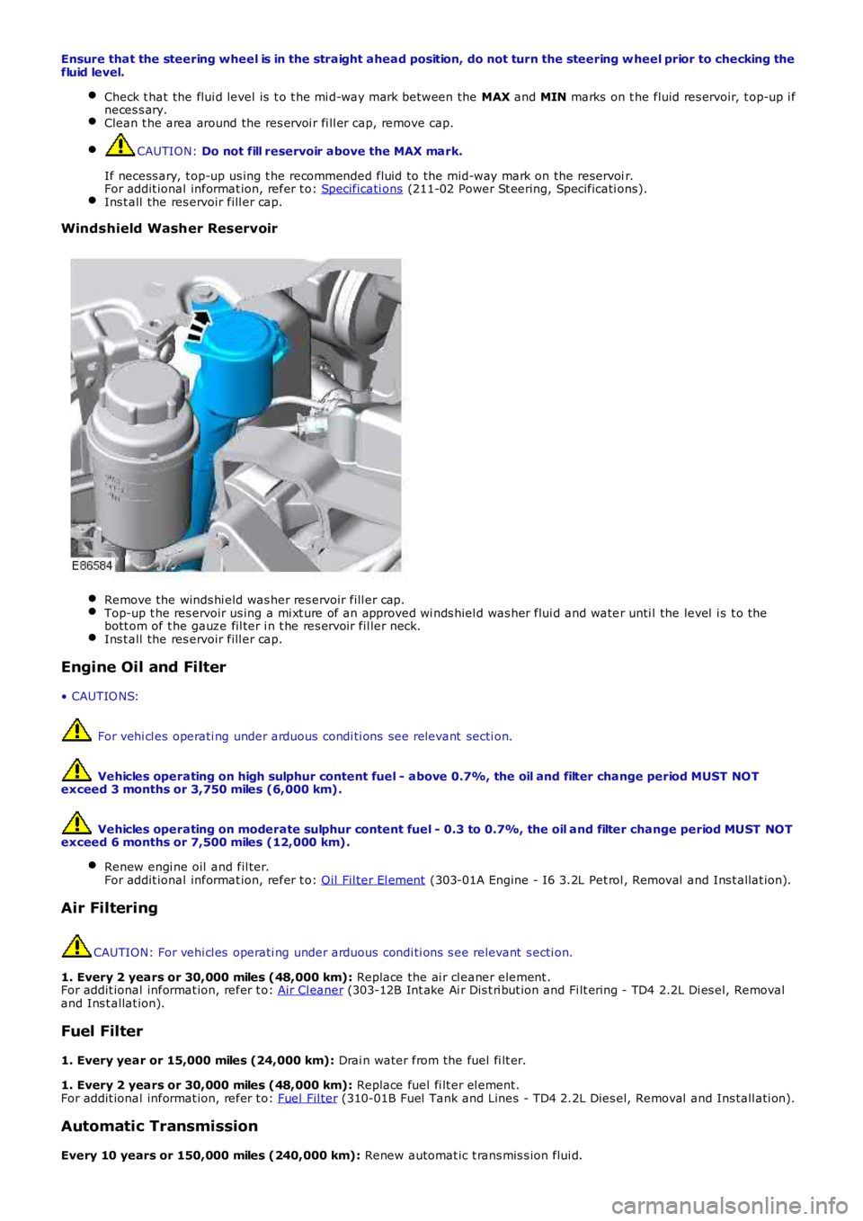
Windshield Washer Reservoir
Remove the winds hi eld was her res ervoir fill er cap.
Top-up t he res ervoir us ing a mi xt ure of an approved wi nds hiel d was her flui d and wate
r unti l the level i s t o the
bott om of t he gauze fil ter i n t he res ervoir fil ler neck. Ins t all the res ervoir fill er cap.
Engine Oil and Filter
• CAUTIO NS: For vehi cl es operati ng under arduous condi ti ons see relevant secti on.
Vehicles operating on high sulphur content fuel - above 0.7%, the oil and filter cha nge period MUST NOT
exceed 3 months or 3,750 miles (6,000 km).
Vehicles operating on moderate sulphur content fuel - 0.3 to 0.7%, the oil and filte r change period MUST NOT
exceed 6 months or 7,500 miles (12,000 km).
Renew engi ne oil and fil ter.
For addit ional informat ion, refer t o: Oil Fil ter El ement (303-01A Engine - I6 3.2L Pet rol , Removal and Ins t allat ion).
Air Filtering
CAUTION: For vehi cl es operati ng under arduous condi ti ons s ee relevant s ecti on.
1. Every 2 years or 30,000 miles (48,000 km): Replace the ai r cl eaner element .
For addit ional informat ion, refer t o: Air Cl eaner (303-12B Int ake Ai r Dis t ri but ion and Fi lt ering - TD4 2.2L Di es el, Removal
and Ins t allat ion).
Fuel Filter
1. Every year or 15,000 miles (24,000 km): Drai n water from the fuel fi lt er.
1. Every 2 years or 30,000 miles (48,000 km): Replace fuel fi lt er el ement.
For addit ional informat ion, refer t o: Fuel Fil ter (310-01B Fuel Tank and Lines - TD4 2.2L Dies el, Removal and Ins tall ati on).
Automatic Transmission
Every 10 years or 150,000 miles (240,000 km): Renew automat ic t rans mis s ion flui d.
Page 192 of 3229
Ins pect rear pads for wear.
Check brake cal ipers for s igns of fl ui d l eaks .
Check brake dis cs for condi ti on.
Check al l brake boos t er and brake s ys t em pipes and hos es for condi ti on, chafi ng and
leaks.Clean road wheel hub s pigot s and appl y greas e, Land Rover Part Number RY L 105020 t o
t he wheel mat ing surface
of each s pigot . Brake Fluid Replacement
CAUTION:
When vehicles are operating under arduous conditions, the following service item mus t be carried out
every 2 Years or 30,000 miles (48,000 km).
Replace brake fluid. Road Wheel Speed Sensors
CAUTION:
When vehicles are operating under arduous conditions, the following service item mus t be carried out
every 3 months or 3,750 miles (6,000 km).
Ins pect the road wheel s peed s ens or harness es for damage. Engine Oil and Filter
• CAUTIO NS:
When vehicles are operating under arduous conditions, the following service item mus t be carried out every 3
months or 3,750 miles (6,000 km).
Vehicles operating on high sulphur content fuel - above 0.7%, the oil and filter cha nge period MUST NOT
exceed 3 months or 3,750 miles (6,000 km).
Vehicles operating on moderate sulphur content fuel - 0.3 to 0.7%, the oil and filte r change period MUST NOT
exceed 6 months or 7,500 miles (12,000 km).
Renew engi ne oil and fil ter. Air Filtering
CAUTION:
When vehicles are operating under arduous conditions, the following service item mus t be carried out
every 12 months or 15,000 miles (24,000 km).
Replace the ai r fi lt er el ement.
For addit ional informat ion, refer t o: Air Cl eaner (303-12A Int ake Ai r Dis t ri but ion and Fi lt ering - I6 3.2L Petrol ,
Removal and Inst all ati on). Accessory Drive Belt
CAUTION:
When vehicles are operating under arduous conditions, the following service item mus t be carried out
every 5 years or 75,000 miles (120,000 km).
Replace the access ory drive bel t. For addi ti onal informat ion, refer to: Acces s ory Drive Belt (303-05A Acces s ory Drive
- I6 3.2L Pet rol, Removal and Ins tal lat ion). Camshaft Timing Belt, Tensioner and Pulley
CAUTION:
When vehicles are operating under arduous conditions, the following service item mus t be carried out
every 4 years or 60,000 miles (96,000 km).
Replace the cams haft t iming belt , tens ioner and pul ley.
For addit ional informat ion, refer t o: Timi ng Belt (303-01B Engi ne - TD4 2.2L Dies el, Removal and Inst all ati on).
Radiator/Charge Air Cooler and Cooling Fan
CAUTION:
When vehicles are operating under arduous conditions, the following items must be ca rried out.
Vis uall y check t he radiat or/charge air cool er for ext ernal obst ruct ions, check cooli ng fan bl ades for damage.Remove any debris from t he charge air cool er us i ng a l ow pres s ure hos e.
Continuous Use In Severe Off-Road Conditions
CAUTION:
After 50 miles (80 km) continuous use in severe off-road conditions i.e. w ading, dee p mud and
abrasive grit/slurry, the following items must be cleaned and inspected.
Page 276 of 3229
The cont rol ling software for t he TPMS i s located wi thi n t he CJB. The s oft ware det ects t he fol lowing:
t he ti re press ure is bel ow t he recommended low pres sure value - under infl ated t iret he pos i ti on of the t ire on t he vehi cle.
The s ys t em compri s es a Radio Frequency (RF) receiver, 4 init iat ors and 4 ti re press ure s ens ors (5 if t he spare wheel has as ens or fi tt ed).
The 4 i nit iators are hard wi red t o t he CJB. The i nit iators t rans mit 125 KHz Low Frequency (LF) s ignals t o t he t ire pres s ures ens ors which res pond by modifying t he mode s t at us wi thin the RF trans mi s si on. The 315 or 433 MHZ RF s ignals aredetected by the RF recei ver whi ch is l ocat ed at the rear of t he vehicle, behi nd t he headl ining. The RF receiver is connect edt o the CJB on the Local Interconnect Net work (LIN) bus . The received RF s i gnals from t he t ire pres s ure s ensors are pas s edt o the CJB on the LIN bus and contain identi fi cat ion, pres sure, temperat ure and accel erat ion i nformat ion for each wheeland t ire.
The TPMS s oft ware communi cat es wit h t he ins trument cl ust er via t he medium s peed Control ler Area Net work (CAN) bus toprovide t he driver wit h appropri at e warnings. The TPMS s oftware als o i ndi cat es s tat us or fail ure of t he TPMS orcomponents .
Tire Location and Identification
The TPMS can identi fy the pos it ion of t he wheel s on t he vehi cle and as s ign a recei ved ti re press ure s ens or identi fi cat ion t oa s peci fi c posi ti on on t he vehi cl e, for exampl e FL (front l eft ), FR (front ri ght ), RL (rear left ) and RR (rear right). Thi s feat ureis required because of the di fferent pres sure t argets and t hres hold bet ween the front and rear t ires.
The wheel l ocat ion i s performed aut omati cal ly by t he TPMS s oft ware us i ng an 'auto-locati on' funct ion. Thi s functi on is full yautomat ic and requi res no i nput from t he dri ver. The TPMS software automat icall y re-learns t he pos it ion of t he wheel s ont he vehi cl e if t he t ire pres s ure s ensors are replaced or the wheel posi ti ons on t he vehi cl e are changed.
The TPMS s oft ware can aut omat icall y detect, under all operati ng condit ions , the following:
one or more new t ire pres sure s ensors have been fit t edone or more ti re press ure s ens ors have s t opped t rans mi tt ingTPMS s oft ware can reject identi fi cat ions from ti re press ure sens ors whi ch do not belong to the vehiclet he spare wheel and one of t he 'runni ng' wheels on the vehicle have changed pos it ions .
If a new t ire pres s ure s ensor i s fi tt ed on any 'running' wheel , the s oft ware can learn t he new s ens or i dent ificati onautomat ically when the vehicle is driven for more t han 15 mi nut es at a s peed of more than 20 km/h (12.5 mph).
• NOTE: The s pare wheel is not fit ted wit h a t ire pres s ure s ens or.
TPMS Operation
Each ti me t he vehi cl e i s dri ven the TPMS s oft ware act ivates each i ni ti ator i n turn to t rans mit a LF 125 KHz s ignal t o eacht ire pres sure s ensor. The LF si gnal i s received by t he ti re pres sure s ens or which responds by t rans mit ti ng a 315 or 433MHZ (depending on market ) si gnal whi ch is received by t he RF recei ver. The si gnal contains coded data which corres pondst o s ens or identi fi cat ion, air pres s ure, air t emperature and accel erati on data. This i s t hen pas s ed to the CJB on the ISO9141 K Line.
If the vehicle has been parked for more than 15 minutes and t hen dri ven at a s peed of more t han 12.5 mph (20 km/h), t heini ti at ors each fire an LF s ignal in turn for 18 s econds i n t he fol lowing order:
Front LHFront RHRear RHRear LH.
Each ti re press ure s ens or res ponds i n t urn whi ch allows the TPMS s oftware to est ablis h the s ensor pos it ions at t he st art oft he drive cycle. This proces s is repeat ed up t o t hree t imes but l ess if t he s ens or pos i ti ons are already known. The processis known as 'Auto Locati on' and t akes 2 to 4 mi nut es t o compl ete.
Duri ng thi s peri od the t ire pres s ure sens ors t rans mi t at regular int ervals , once every 5 s econds (once every 15 s econds onNAS vehicles ). For the remainder of the drive cycl e t he t ire pres sure s ensors transmit once every 60 s econds or more oft enif a change of ti re pres sure is sens ed unti l the vehicle st ops and the TPMS ret urns t o t he parking mode.
Once the wheel pos it ions have been es t abl is hed, t he i ni ti ators s top t rans mit t ing t he LF s ignal and do not t rans mi t agai nunti l the vehicle has been parked for more than 15 minutes .
The warni ng appears in t he i ns t rument clus ter mes s age cent re when the i nfl at ion press ure has fal len t o 25% of t henominal pres s ure. The dis played mes sage wi ll als o i ncl ude the pos it ion(s) of t he affect ed wheel(s).
The TPMS enters 'Parki ng Mode' aft er the vehicl e s peed has been l es s t han 20 km/h (12.5 mph) for 15 minut es . In parkingmode t he t ire pres sure s ensors transmit a coded RF s ignal once every 13 hours. If t he ti re pres sure decreas es by more
t han 0.06 bar (1 lbf/in2 ), t he s ens or wil l trans mi t more oft en if pres s ure in t he t ire is bei ng los t.
The s pare wheel ti re press ure s ens or als o t rans mit s a si gnal once every 13 hours i n t he s ame manner as the 'running
wheels ' when in parki ng mode. If t he t ire pres sure decreases by more t han 0.06 bar (1 l bf/i n2 ), the s ensor wi ll t rans mitmore oft en if press ure in t he t ire is bei ng los t .
Initiators
Page 277 of 3229
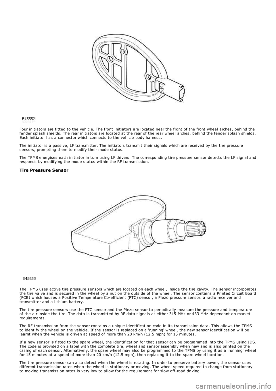
Four i nit iators are fi tt ed t o the vehicl e. The front i ni ti ators are l ocat ed near t he front of the front wheel arches , behind t hefender s pl ash shi elds . The rear init iat ors are located at t he rear of t he rear wheel arches , behind t he fender spl ash shi el ds.Each init iat or has a connect or which connects to the vehicle body harnes s .
The ini ti at or is a pass ive, LF t rans mit ter. The init iat ors t rans mi t their s ignals which are recei ved by the ti re press ures ens ors , prompt ing them to modi fy their mode st atus .
The TPMS energis es each init iat or in t urn usi ng LF dri vers. The corres ponding t ire pres s ure sens or det ect s t he LF s ignal andres ponds by modifyi ng the mode s tat us wit hin t he RF t rans mis s ion.
Tire Pressure Sensor
The TPMS us es act ive t ire pres s ure s ens ors whi ch are l ocat ed on each wheel , ins ide the ti re cavit y. The sens or incorporat est he ti re val ve and is s ecured in the wheel by a nut on t he outs i de of the wheel. The s ensor contains a Pri nt ed Ci rcuit Board(PCB) whi ch hous es a Pos it ive Temperat ure Co-efficient (PTC) s ens or, a Piezo pres s ure s ens or. a radi o receiver andt ransmit ter and a l it hium bat t ery.
The t ire pres sure s ensors use the PTC sens or and the Pi ezo sens or to periodically measure t he pres sure and t emperatureof the ai r ins ide t he t ire. The dat a is trans mi tt ed by RF dat a s ignals at ei ther 315 MHz or 433 MHz dependant on marketrequirements .
The RF t rans mis s ion from t he sens or cont ai ns a unique i dent ificati on code in i ts trans mi ss i on dat a. This all ows t he TPMSt o identi fy the wheel on t he vehi cl e. If t he s ens or is replaced on a 'running' wheel, t he new s ens or i dent ificati on wil l belearnt when the vehicle is driven at s peed of more t han 20 km/h (12.5 mph) for 15 minutes .
If a new s ensor i s fi tt ed t o t he spare wheel, t he identi fi cat ion for that s ens or can be programmed int o t he TPMS usi ng IDS.The code is provi ded on a l abel wit h t he complet e ti re, wheel and sens or ass embly when new and is al s o pri nted on t hecas i ng of each s ensor. Alt ernati vel y, t he s pare wheel may al so be programmed to the TPMS by us i ng it as a 'running' wheelfor 15 minutes at a speed of more t han 20 km/h (12.5 mph), t hen replacing it t o t he spare wheel l ocat ion.
The t ire pres sure s ensor can als o det ect when t he wheel i s rot ati ng. In order t o preserve bat t ery power, t he s ens or us esdifferent t rans mis s ion rates when the wheel is st ati onary or moving. The wheel s peed required to change from st ati onaryt o moving t rans mis s ion rates is very low t o al low for the requi rement for sl ow off-road dri ving.
Page 284 of 3229
Publi s hed: 11-May-2011
Wheels and Tires - Tire Low Pressure Sensor
Removal and Inst all ati on
Removal
W ARNING: The val ve seal and s teel was her mus t be replaced each t ime a t ire is changed to avoi d s eal failure. Thes eal and was her must be replaced if t he s ensor i s removed. Removal of the sens or retai ning nut mus t be regarded ass ens or removal. The valve cap mus t always be in pl ace except when i nfl at ing, rel easing or checki ng pres s ure.
• NOTE: If the s ens or i s repl aced on a 'runni ng' wheel, t he new s ens or ident ifi cat ion will be learnt when t he vehi cl e i s fi rs tdri ven. If a new s ensor i s ins t al led t o t he s pare wheel, t he ident ifi cat ion for that s ensor mus t be programmed i nto t he t irepres s ure moni toring s yst em (TPMS) module us ing Land Rover approved di agnos ti c equi pment . The ident ifi cat ion code i sprovided on a label wit h t he compl ete as s embly and i s als o print ed on t he cas ing of each s ens or.
1. W ARNING: Make sure t o s upport the vehicle wit h axles tands .
Rais e and s upport t he vehi cl e.
1.
Remove t he wheel and t ire.
Refer t o: W heel and Ti re (204-04 W heel s and Tires, Removal andInst all at ion).
2.
3. CAUTION: To avoid damage t o t he t ire low pres sure s ens or,rel ease the t ire bead from the rim, 180 degrees from t he val ve.
Remove t he ti re from t he wheel.
3.
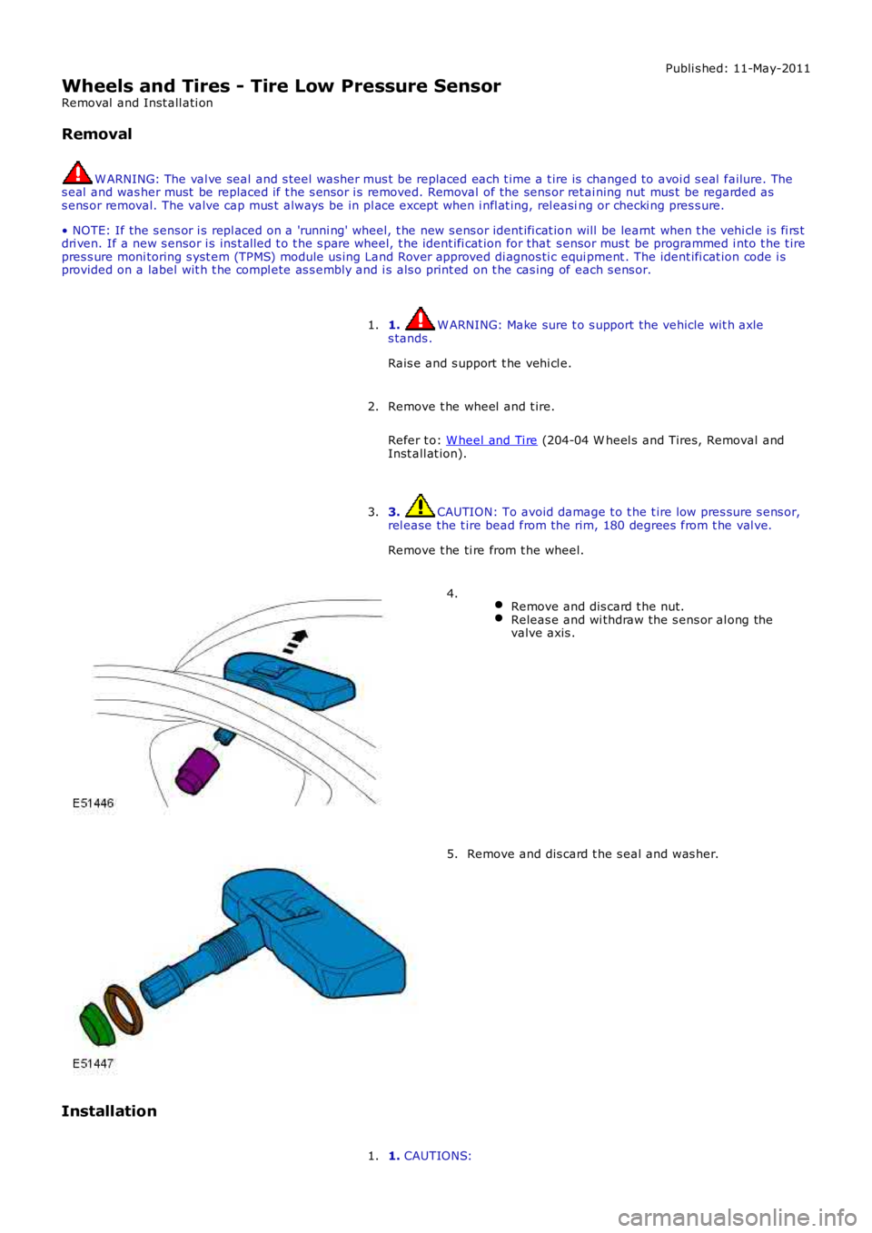
Remove and dis card t he nut.Releas e and wi thdraw the s ens or al ong thevalve axis .
4.
Remove and dis card t he s eal and was her.5.
Installation
1. CAUTIONS:1.
Page 295 of 3229
Each sub-sys tem operates in di fferent ways in relati on t o t he sel ect ed Terrai n Res pons e program t o achieve t he opt imumt racti on, s t abi lit y and eas e of cont rol for t he t errai n encount ered.
Engine Management System (EMS)
The EMS can change t he accel erator pedal maps to change the amount of t orque per percent age of pedal travel .
Each terrain program uses a combi nat ion of operat ing paramet ers for each sub-sys tem. Changing bet ween terrain programsini ti at es a di fferent s et of operat ing characteris ti cs which wil l be noti ceable to the driver, for example; i f the accel erat orpedal i s held i n a const ant pos i ti on and the terrain program is changed from Gras s /Gravel /Snow t o Sand, the driver wil lnoti ce the t orque and engine s peed increas e. If t he t errai n program is changed from Sand t o Grass /Gravel/Snow, t he dri verwil l not ice a reduct ion in t orque and engine s peed.
• NOTE: The change i n t orque and engine s peed can take approximat ely 30 s econds and care mus t be taken not to confus et he Terrai n Respons e s yst em operat ion wit h an EMS faul t.
Transmission Control (Automatic transmission only)
The t ransmis s ion control modul e changes t he shi ft maps for the Terrain Respons e program s elect ed. Thi s changes t he s hi ftpoints providing early or l at e ups hift s and downs hi ft s .
For example, i n t he Gras s /Gravel /Snow program, the trans mi ss i on wil l perform early ups hi ft s and very late downs hifts toensure t he transmis si on is in t he highes t gear pos si ble. The hil l det ect ion funct ion of t he Trans mis s ion Cont rol module(TCM) will l ock t he t orque converter and hold whi chever gear i s s el ect ed t o t he engine s peed (RPM) li mit i f neces s ary whendescending a s t eep incli ne. This provi des maximum engi ne braking before t he dri ver needs t o appl y t he brakes.
Sport mode i s only avail abl e when t he general program i s s elected. Sport mode i s disabled i n all Terrain Res pons e s peci alprograms. 'CommandShift ™' is avail abl e in any program.
Active On-Demand Coup ling Control
The act ive on-demand coupli ng cont rol module has 2 operati ng s trat egies ; pre-empt ive and react ive.
The pre-empti ve st rat egy anti ci pat es and predict s the locki ng torque val ue required t o mi ni mi ze sl ip and maxi mizes tabil it y. Each Terrain Res pons e program has a different t hres hol d and i nput cri teria for the pre-empt ive s t rategy. Forexampl e, a higher locki ng t orque would be appl ied on s li ppery s urfaces .
The reacti ve s trategy vari es the amount of locking t orque in res pons e t o t he actual s lip level and t he dynamic behavi or oft he vehi cl e. Each Terrain Res pons e program has a different t hres hol d and input for the react ive s trategy. The reacti ves trategy i mproves vehi cl e t racti on and compos ure by eliminati ng any wheel s pin which has occurred aft er the pre-empt ives trategy was appli ed. The l ocking res pons e appli ed is appli cable to the t errain program sel ect ed. For exampl e, verys ens i ti ve on s lippery surfaces to provide maximum t racti on and mi nimi ze surface damage.
The locking t orque calculati ons use various s ignals from other s ub-s yst ems , for example, engi ne torque, accel erator pedalposi ti on, s elect ed gear, st eeri ng angl e, vehicle s peed, lat eral accelerat ion, yaw behavi or.
The DSC funct ion of t he ABS s ys t em can override t he act ive on-demand coupli ng cont rol and reduce any appl ied l ocki ngt orque during DSC act ion.
ABS System Control
The ABS module cont rols several functi ons and adjust s t he operati ng paramet ers of t hes e funct ions t o opti mize thes elect ed Terrain Res pons e program.
Tracti on Control
Tracti on cont rol us es different s li p/accel erati on thresholds to i mprove t ract ion and vehicle compos ure. For example, t hes ys t em s ens it ivit y is increased on s lippery surfaces s uch as wet grass or s now t o reduce wheel s pi n. If wheel s pi n wasall owed in t hese ci rcums tances, l oss of t ract ion may res ul t from surface damage (wet grass ) or t he car being unable tomove (snow) due t o wheel spi n.
Dynamic St abi li ty Cont rol
If DSC is s wi tched off (wit h t he DSC s wi tch adjacent to t he Terrain Res pons e rotary cont rol ) when usi ng a TerrainRespons e s peci al program, if t he s peci al program i s s ubs equent ly changed for a di fferent program, DSC is aut omat icall ys wit ched back on.
The DSC us es different t hres hol d values for t he s elected program t o aut omati call y reduce DSC i ntervent ion, removing t herequirement for t he dri ver t o dis able t he DSC s ys tem in order to reduce engine intervent ion whi ch is s omet imes i nduced i nextreme off-road condi ti ons . In ext reme s and condit ions , there may be an addit ional benefit of dis abling the DSC funct ionus ing t he DSC s wit ch in addi ti on to sel ect ing t he s and program.
In the Mud/Ruts program the DSC sys tem is cal ibrat ed t o tol erate a higher 'yaw' thres hold. This al lows a greaterdifferent ial between t he actual and des i red wheel turni ng behavi or before DSC i ntervenes . Thi s all ows the DSC s ys t em t oignore the effect of rut s 'jarring' t he car or adjust ing t he front wheel s t eering angle.
The Terrai n Res pons e s ys tem can al ter t he balance bet ween engine and brake i ntervention. For example, when t he s andprogram is sel ect ed, t he DSC s ys tem reduces it s rel iance on engi ne int erventi on and increas es the us e of brakeint erventi on to maint ai n t he vehi cl es momentum and prevent it from becomi ng bogged down i f wheel s li p i s detected.
Hil l Descent Cont rol
HDC i s automat icall y s wit ched on or off and target s peeds are adjus t ed in res pons e to t he Terrai n Res pons e programs elect ed. The res pons iveness of the HDC functi on is al so increas ed where requi red.
Automat ic operat ion of HDC ai ms t o as s is t the driver by s wit chi ng t he sys t em on or off when it is of most benefi t. HDC isonly aut omat icall y s wit ched on when the mud/rut s program i s s elect ed. HDC i s not automati cal ly s elected in ot her
Page 319 of 3229
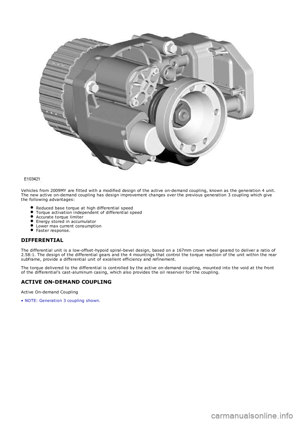
Vehicles from 2009MY are fit ted wit h a modi fied des ign of t he acti ve on-demand coupling, known as the generat ion 4 uni t.The new acti ve on-demand coupl ing has desi gn improvement changes over t he previous generati on 3 coupl ing whi ch gi vet he foll owing advant ages:
Reduced bas e t orque at high different ial s peedTorque acti vat ion i ndependent of different ial s peedAccurat e t orque l imi terEnergy s tored in accumulat orLower max current cons umpt ionFast er res pons e.
DIFFERENTIAL
The different ial unit i s a l ow-offs et -hypoid spi ral-bevel des ign, bas ed on a 167mm crown wheel geared t o deli ver a rat io of2.58:1. The des ign of t he different ial gears and t he 4 mount ings t hat control t he t orque react ion of t he uni t wit hin the rears ubframe, provi de a different ial unit of excel lent efficiency and refinement.
The t orque delivered to the di fferenti al i s cont rol led by t he acti ve on-demand coupli ng, mount ed int o t he voi d at t he frontof the di fferenti al's cas t-alumi num casi ng, whi ch als o provi des t he oil reservoi r for t he coupli ng.
ACTIVE ON-DEMAND COUPLING
Acti ve On-demand Coupl ing
• NOTE: Generati on 3 coupling shown.
Page 512 of 3229
The HDC s wi tch i s non-lat chi ng and is ins tall ed in the floor cons ole, forward of the gear s el ect or lever. Moment aril ypres s ing and releasi ng t he HDC s wit ch connects an ignit ion power feed t o t he ABS module. W it h t he fi rs t pres s and rel easeof the HDC s wit ch, t he ABS module enables operat ion of t he HDC funct ion. W hen t he HDC swi tch i s pres s ed and rel eas edagai n, the ABS modul e dis ables operat ion of t he HDC funct ion.
To prevent mis -use of, or in the event of a broken HDC s wi tch, if t he s wit ch is press ed for more t han 10 s econds nochange of s tat e occurs. A DTC i s s tored in t he ABS module memory if t he input from the HDC swi tch i s held hi gh for moret han 1 mi nut e.
HDC Activating Stoplamps
Operat ion of t he vehi cl e s toplamps during HDC is controll ed by the CJB. The ABS module monit ors t he brake s yst emhydraulic press ure and request s t he CJB, vi a t he high s peed CAN bus, t o energi ze the s t opl amps duri ng act ive braki ng.
A press ure thres hold and ti me fil ter prevents t he s topl amps from fli ckeri ng whil e HDC i s braking.
Stop/St art Vehicl es - From 2010 MY
Acti vat ion of Hi ll Descent Cont rol wi ll deact ivate the St op/St art s yst em. However, if Hi ll Des cent Control i s acti vat ed whent he engi ne is s hutdown in a St op/St art cycl e t he engi ne wil l aut omati cal ly rest art . If during t his event the St op/St arts ys t em cannot det ect t he dri ver's occupancy, for exampl e eit her t he driver’s safety belt or door is unl at ched, t he engi newil l not res tart. The St op/Start sys tem wi ll request the driver to depres s t he clut ch to res tart the engine. The dri ver wi ll beinformed of t his by ‘RESTART REQUIRED PRESS CLUTCH’ being di spl ayed i n t he mes sage center.
The dri ver mus t respond t o t hi s reques t wit hin a li mit ed t ime period, or otherwi s e a convent ional engine res tart us i ng theignit ion swi tch will be requi red.For addit ional informat ion, refer t o: Starti ng Sys t em (303-06C Starti ng Syst em - TD4 2.2L Di es el, Vehicles Bui lt From:01-03-2009, Descripti on and Operat ion).
WHEEL SPEED SENSORS