2006 LAND ROVER FRELANDER 2 air suspension
[x] Cancel search: air suspensionPage 34 of 3229
Air Suspension
W henever work is bei ng undertaken on t he air s us pens ion s ys tem, s uit able eye prot ection must be worn.
Air Conditioning Refrigerant
Highly fl ammable, combus t ible – observe No Smoking poli cy.
Skin contact may res ult in fros tbi te.
Ins t ructi ons gi ven by the manufact urer mus t be followed. Avoi d naked li ght s , wear s uit able protecti ve gloves and goggles .
If refrigerant comes int o contact wit h t he s ki n or eyes , rins e t he affect ed areas with wat er immedi ately. Eyes s houl d als obe rins ed wit h an appropriate irri gat ion s olut ion s uch as a s olut ion of 9% Sodi um Chl oride and Purified W at er. DO NOTRUB T HE EYES AND SEEK IMMEDIAT E MEDICAL AT T ENT ION.
Air Conditioning Refrigerant
Do Not
Do Not expos e refrigerant bott les to s unli ght or heat.Do Not expos e refrigerant bott les to fros t .Do Not drop refrigerant bot tl es .Do Not vent refrigerant t o at mos phere under any circums t ance.Do Not mi x refri gerants .
Adhesives and Sealants
Many adhes ives and s ealants are hi ghl y fl ammable – OBSERVE NO SMOKING POLICY . Thes e it ems , s hould be s tored infl ameproof cabi net s in No Smoking areas . Cleanli nes s and t idi nes s i n us e s houl d be obs erved, for exampl e dis posablepaper covering benches . All adhesi ves and sealant s s houl d be dis pensed from applicators where pos s ibl e; contai ners ,including secondary cont ainers , s houl d be l abell ed appropri at ely.
Anaerobic, Cyanoacrylate (super-g lues) and other Acrylic Ad hesives
Many are irrit ant, s ensi ti zing or harmful to the s kin and res pirat ory t ract . Some are eye i rrit ants .
Skin and eye contact should be avoi ded and the manufact urer's ins t ructi ons foll owed.
Cyanoacrylat e adhes i ves (s uper-gl ues ) MUST NOT cont act t he s ki n or eyes . If s ki n or eye ti s sue i s bonded, cover wi th aclean moi st pad and SEEK IMMEDIAT E MEDICAL AT T ENT ION. Do not att empt to pul l ski n t is sue apart. Us e i n wellvent il ated areas as vapors can caus e irri tat ion t o t he nose and eyes .
For two-pack s yst ems s ee Res in-bas ed and Is ocyanat e Adhesi ves /Seal ers .
Solvent-based Adhesives/Sealers - See Solvents
Follow manufacturers ins t ructi ons .
Water-based Adhesives/Sealers
Thos e bas ed on polymer emul si ons and rubber/latex may cont ain s mal l amount s of vol ati le, toxic and harmful chemicals .Skin and eye contact should be avoi ded and adequate vent ilat ion provi ded during us e.
Hot Melt Adhesives
In the sol id s t ate, t hey are s afe. In t he molt en s tat e t hey may caus e burns and healt h hazards may aris e from t heinhalat ion of t oxi c fumes .
Us e appropri at e protecti ve cl othing and a t hermos tat ical ly controll ed heat er wit h a t hermal cut-out and adequateextract ion.
Resin-based Adhesives/Sealers, for examp le Epoxide and Formaldehyde Resin-based
Mixi ng s hould be carri ed out in wel l vent il at ed areas as harmful or t oxi c vol ati le chemicals may be rel eas ed.
Skin contact wit h uncured res i ns and hardeners can res ult i n irri tat ion, dermat it is , and abs orpt ion of t oxic or harmfulchemical s t hrough the ski n. Splas hes can damage the eyes .
Provide adequat e venti lat ion and avoid s kin and eye contact .
Isocyanate (Polyurethane) Ad hesives/Sealers
See als o Res in-bas ed Adhesi ves
Indi vi dual s s uffering from as thma or res pi rat ory al lergi es should not work wi th or near thes e mat eri al s as s ensi ti vi tyreacti ons can occur.
Over expos ure i s irri tat ing t o t he eyes and res pirat ory sys tem. Excess ive concent rations may produce effects on thenervous s ys t em i ncl udi ng drows ines s. In extreme cas es , l os s of conscious ness may result . Long term expos ure to vapourconcentrati ons may res ult i n adverse heal th effect s.
Prol onged contact wit h t he s ki n may l ead to s ki n irri tat ion and i n s ome cas es , dermat it is .
Splas hes ent eri ng the eye wi ll cause di s comfort and pos si ble damage.
Page 179 of 3229
Check t hat the flui d level is t o t he mi d-way mark between the MAX and MIN marks on t he fluid res ervoir, t op-up i fneces s ary.Clean t he area around the res ervoi r fi ll er cap, remove cap.
CAUTION: Do not fill reservoir above the MAX mark.
If necess ary, t op-up us ing t he recommended fluid to the mid-way mark on the reservoir.For addit ional informat ion, refer t o: Specificati ons (211-02 Power St eering, Specificati ons).Ins t all the res ervoir fill er cap.
Windshield Washer Reservoir
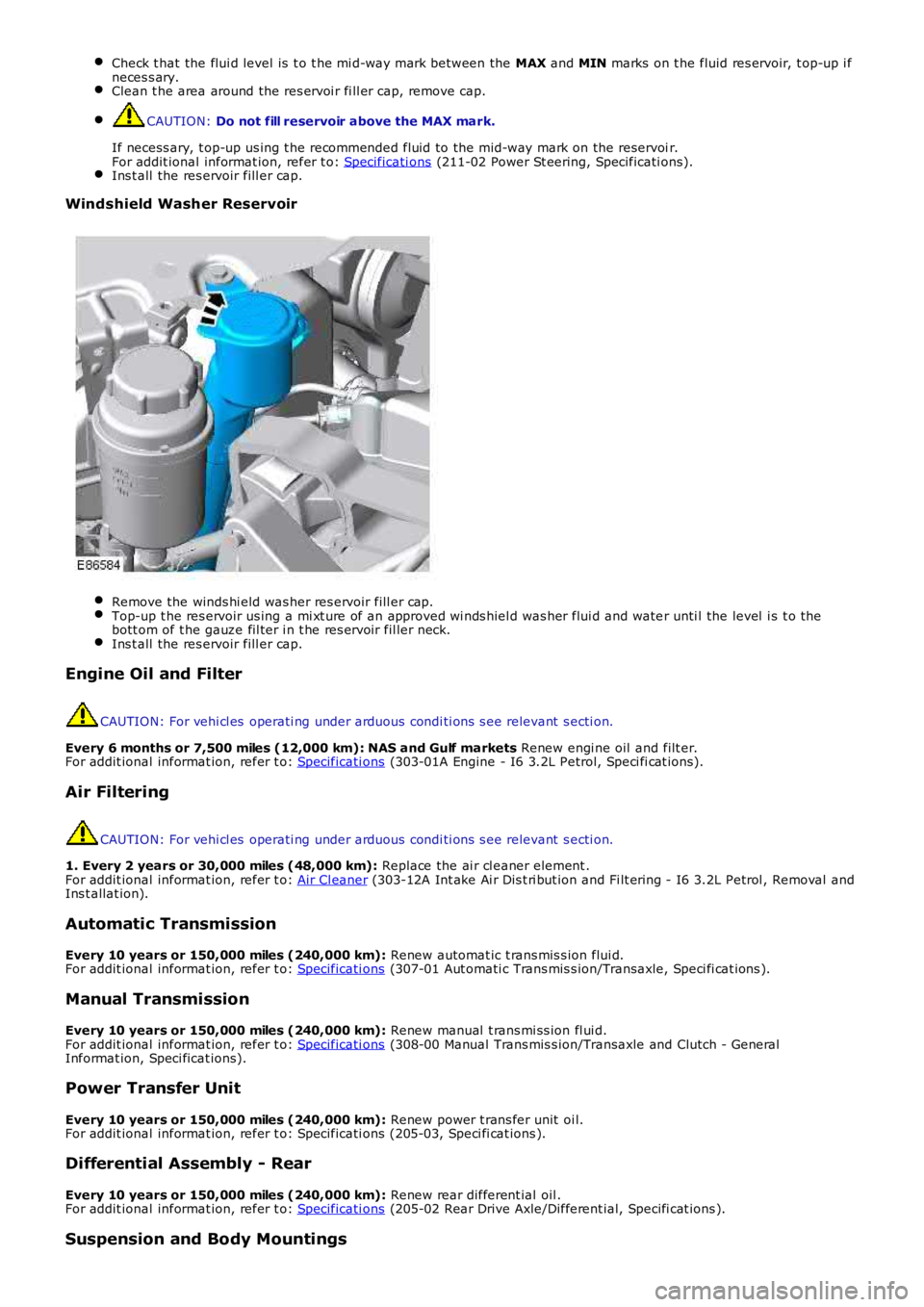
Remove the winds hi eld was her res ervoir fill er cap.Top-up t he res ervoir us ing a mi xt ure of an approved wi nds hiel d was her flui d and water unti l the level i s t o thebott om of t he gauze fil ter i n t he res ervoir fil ler neck.Ins t all the res ervoir fill er cap.
Engine Oil and Filter
CAUTION: For vehi cl es operati ng under arduous condi ti ons s ee relevant s ecti on.
Every 6 months or 7,500 miles (12,000 km): NAS and Gulf markets Renew engi ne oil and filt er.For addit ional informat ion, refer t o: Specificati ons (303-01A Engine - I6 3.2L Petrol, Speci fi cat ions).
Air Filtering
CAUTION: For vehi cl es operati ng under arduous condi ti ons s ee relevant s ecti on.
1. Every 2 years or 30,000 miles (48,000 km): Replace the ai r cl eaner element .For addit ional informat ion, refer t o: Air Cl eaner (303-12A Int ake Ai r Dis t ri but ion and Fi lt ering - I6 3.2L Petrol , Removal andIns t allat ion).
Automatic Transmission
Every 10 years or 150,000 miles (240,000 km): Renew automat ic t rans mis s ion flui d.For addit ional informat ion, refer t o: Specificati ons (307-01 Aut omati c Trans mis s ion/Transaxle, Speci fi cat ions ).
Manual Transmission
Every 10 years or 150,000 miles (240,000 km): Renew manual t rans mi ss ion fl ui d.For addit ional informat ion, refer t o: Specificati ons (308-00 Manual Trans mis s ion/Transaxle and Clutch - GeneralInformat ion, Speci ficat ions).
Power Transfer Unit
Every 10 years or 150,000 miles (240,000 km): Renew power t rans fer unit oi l.For addit ional informat ion, refer t o: Specificati ons (205-03, Speci fi cat ions ).
Differential Assembly - Rear
Every 10 years or 150,000 miles (240,000 km): Renew rear different ial oil .For addit ional informat ion, refer t o: Specificati ons (205-02 Rear Drive Axle/Different ial, Specifi cat ions ).
Suspension and Body Mountings
Page 195 of 3229
Publi s hed: 11-May-2011
Suspension System - General Information - Suspension System
Diagnosi s and Tes ti ng
Principles of Operation
For a detail ed descripti on of the sus pens i on sys t em, refer t o t he rel evant Des cript ion and Operat ion s ecti on in theworks hop manual . REFER to:
Front Sus pensi on (204-01 Front Sus pensi on, Des cri pti on and Operati on),Rear Sus pens ion (204-02 Rear Suspens ion, Descri pti on and Operat ion),Ride and Handli ng Opti mizati on (204-06 Ride and Handli ng Opti mizat ion, Descri pti on and Operat ion).
Inspection and Verification
1. Verify t he cus t omer concern.1.
2. Vis ually ins pect for obvious s igns of damage.2.
Visual InspectionMechanical
Damaged t iresW heel bearing(s)Loose or damaged front or rear s uspens ion component sLoose, damaged or mis s ing s us pens ion fas tener(s )Incorrect spring(s ) i ns t alledDamaged or s aggi ng spring(s )Damaged or leaking s hock abs orber(s )Damaged or leaking s t rut (s )W orn or damaged s us pensi on bushi ng(s )Loose, worn or damaged s t eering sys tem componentsDamaged axle component s
3. If an obvious cause for an obs erved or report ed concern is found, correct t he caus e (if pos s ible) beforeproceeding t o t he next s t ep.3.
4. If t he caus e is not vis ually evi dent , verify t he sympt om and refer t o t he Sympt om Chart.4.
Symptom Chart
SymptomPossible CauseAction
CrabbingIncorrect rear thrus t angleFront or rear s uspens ioncomponent sDrive axle damaged
CHECK t he rear toe adjust ment.REFER to: Speci fi cat ions (204-00 Suspens ion Syst em - GeneralInformat ion, Specificati ons) /Four-W heel Al ignment (204-00 Sus pens i on Sys t em - GeneralInformat ion, General Procedures ).INSPECT t he front and rear s us pensi on s yst ems . REPAIR orINSTALL new s us pens ion component s as neces s ary. INSTALL a newrear dri ve axl e/di fferenti al as necess ary
Drift/Pul lUnequal t ire pres s ureIncorrect wheel ali gnmentTiresUnevenl y loaded oroverloaded vehi cleDamaged s teeri ngcomponent sBrake drag
CHECK and ADJUST the t ire pres s ures . INSPECT t he ti re forexces si ve wear.REFER to: Speci fi cat ions (204-04 W heels and Ti res , Specificati ons ).CHECK and ADJUST the wheel ali gnment .REFER to: Four-W heel Al ignment (204-00 Sus pensi on Syst em -General Informat ion, General Procedures ).CHECK and ADJUST the t ire pres s ures . INSPECT t he ti re forexces si ve wear.REFER to: Speci fi cat ions (204-04 W heels and Ti res , Specificati ons ).NOTIFY the cus tomer of incorrect vehicle l oadi ng. CHECK thes teeri ng s ys t em.REFER to: St eering Sys tem (211-00 St eeri ng Sys t em - GeneralInformat ion, Diagnosi s and Test ing).CHECK t he brakes .REFER to: Brake Sys tem (206-00 Brake Syst em - GeneralInformat ion, Diagnosi s and Test ing).Front Bott omi ng orRidi ng LowCoil s pri ngsCHECK t he ri de hei ght. INSTALL new springs as neces s ary.REFER to: Spri ng (204-01 Front Sus pensi on, Removal andIns t al lat ion) /Rear Shock Absorber (204-02 Rear Sus pensi on, Removal andIns t al lat ion).
Incorrect Ti re W earIncorrect ti re press ure(rapid center rib or i nnerand outer edge wear)Exces s ive front or rear toe(rapid inner or out er edgewear)Exces s ive negat ive orposi ti ve camber (rapi dinner or out er edge wear)Tires out of bal ance (ti rescupped or dis hed)
CHECK and ADJUST the t ire pres s ure. INSPECT t he t ire forexces si ve wear.REFER to: Speci fi cat ions (204-04 W heels and Ti res , Specificati ons ).CHECK and ADJUST the wheel ali gnment .REFER to: Four-W heel Al ignment (204-00 Sus pensi on Syst em -General Informat ion, General Procedures ).BALANCE the wheels /ti res
Page 2546 of 3229
Publis hed: 11-May-2011
Front End Sheet Metal Repairs - Front Side Member and Suspension Top Mount
AssemblyRemoval and Ins tallat ion
Removal
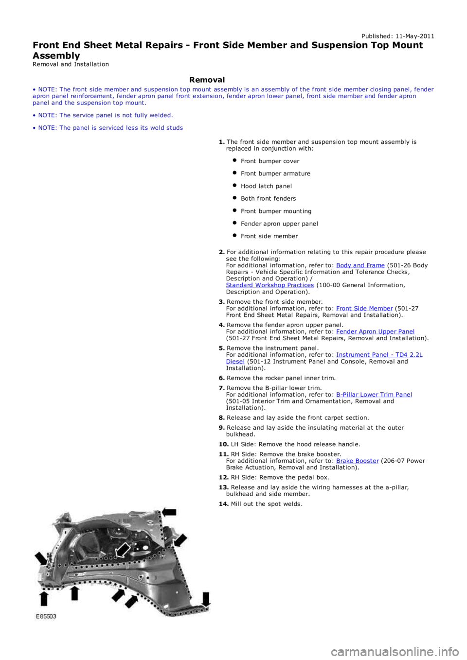
• NO TE: The front s ide member and suspens ion t op mount as sembly is an ass embly of the front s ide member closing panel, fenderapron panel reinforcement, fender apron panel front ext ens ion, fender apron lower panel, front s ide member and fender apronpanel and the s uspens ion t op mount .
• NO TE: The service panel is not fully welded.
• NO TE: The panel is serviced les s it s weld s tuds
1. The front side member and suspens ion t op mount as sembly isreplaced in conjunct ion wit h:
Front bumper cover
Front bumper armat ure
Hood lat ch panel
Both front fenders
Front bumper mount ing
Fender apron upper panel
Front side member
2. For addit ional information relating t o t his repair procedure pleas es ee t he following:For addit ional informat ion, refer to: Body and Frame (501-26 BodyRepairs - Vehicle Specific Informat ion and Tolerance Checks ,Des cript ion and O perat ion) /Standard W orkshop Pract ices (100-00 General Informat ion,Des cript ion and O perat ion).
3. Remove t he front s ide member.For addit ional informat ion, refer to: Front Side Member (501-27Front End Sheet Met al Repairs, Removal and Ins t allat ion).
4. Remove t he fender apron upper panel.For addit ional informat ion, refer to: Fender Apron Upper Panel(501-27 Front End Sheet Met al Repairs, Removal and Ins t allat ion).
5. Remove t he ins t rument panel.For addit ional informat ion, refer to: Inst rument Panel - TD4 2.2LDiesel (501-12 Inst rument Panel and Cons ole, Removal andIns t allat ion).
6. Remove t he rocker panel inner t rim.
7. Remove t he B-pillar lower t rim.For addit ional informat ion, refer to: B-Pillar Lower Trim Panel(501-05 Int erior Trim and Ornamentat ion, Removal andIns t allat ion).
8. Releas e and lay as ide t he front carpet sect ion.
9. Releas e and lay as ide t he ins ulat ing mat erial at t he out erbulkhead.
10. LH Side: Remove the hood releas e handle.
11. RH Side: Remove the brake boost er.For addit ional informat ion, refer to: Brake Boost er (206-07 PowerBrake Act uat ion, Removal and Ins t allat ion).
12. RH Side: Remove the pedal box.
13. Release and lay aside t he wiring harnes ses at t he a-pillar,bulkhead and s ide member.
14. Mill out t he spot welds .
Page 2554 of 3229
Publi s hed: 11-May-2011
Front End Sheet Metal Repairs - Suspension Top Mount
Removal and Inst all ati on
Removal
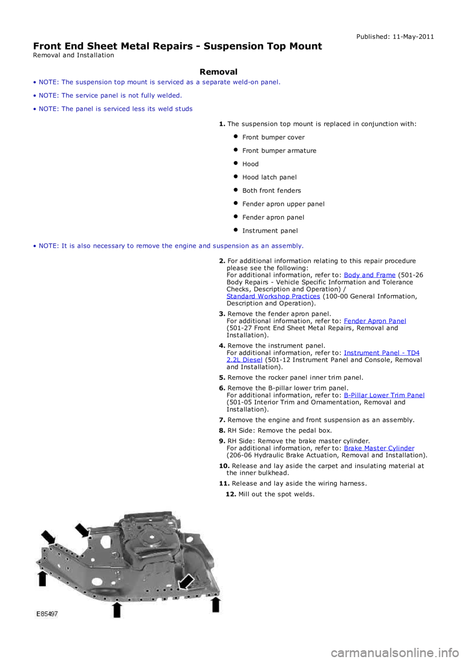
• NOTE: The s uspens ion t op mount is s ervi ced as a s eparate wel d-on panel.
• NOTE: The s ervice panel is not ful ly wel ded.
• NOTE: The panel i s s erviced les s i ts wel d s t uds
1. The sus pens i on top mount i s repl aced i n conjunct ion wi th:
Front bumper cover
Front bumper armature
Hood
Hood lat ch panel
Both front fenders
Fender apron upper panel
Fender apron panel
Ins t rument panel
• NOTE: It is al so neces sary t o remove t he engine and s us pens ion as an as s embly.
2. For addit ional informati on rel at ing to this repair procedurepleas e s ee t he foll owing:For addi ti onal informat ion, refer t o: Body and Frame (501-26Body Repai rs - Vehi cl e Speci fic Informat ion and ToleranceChecks , Descripti on and Operat ion) /Standard W orks hop Practi ces (100-00 General Informat ion,Des cript ion and Operat ion).
3. Remove the fender apron panel.For addi ti onal informat ion, refer t o: Fender Apron Panel(501-27 Front End Sheet Met al Repairs , Removal andIns t allat ion).
4. Remove the i nst rument panel.For addi ti onal informat ion, refer t o: Ins t rument Panel - TD42.2L Di esel (501-12 Ins t rument Panel and Cons ole, Removaland Ins t allat ion).
5. Remove the rocker panel i nner t ri m panel.
6. Remove the B-pill ar lower trim panel .For addi ti onal informat ion, refer t o: B-Pi ll ar Lower Tri m Panel(501-05 Int eri or Trim and Ornament ati on, Removal andIns t allat ion).
7. Remove the engine and front s uspens ion as an as s embly.
8. RH Side: Remove t he pedal box.
9. RH Side: Remove t he brake mas ter cylinder.For addi ti onal informat ion, refer t o: Brake Mas t er Cyli nder(206-06 Hydraulic Brake Actuati on, Removal and Ins t al lat ion).
10. Rel eas e and l ay as ide t he carpet and ins ul ati ng mat erial att he inner bul khead.
11. Rel eas e and l ay as ide t he wiring harnes s .
12. Mil l out t he s pot wel ds.
Page 2557 of 3229
Publ is hed: 11-May-2011
Front End Sheet Metal Repairs - Front Side Member Section
Removal and Installation
Removal
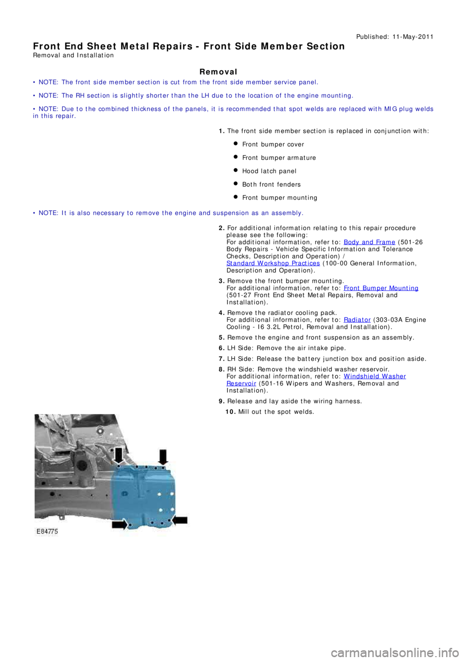
• NOTE: The front side member section is cut from the front side member service panel.
• NOTE: The RH section is slightly shorter than the LH due to the location of the engine mounting.
• NOTE: Due to the combined thickness of the panels, it is recommended that spot welds are replaced with MIG plug welds
in this repair.
1. The front s ide member s ect ion is replaced in conjunct ion wit h:
Front bumper cover
Front bumpe r a rma t ure
Hood lat ch panel
Both front fenders
Front bumpe r mount i ng
• NOTE: It is also necessary to remove the engine and suspension as an assembly.
2. Fo r a d d i t i o na l i nf o rma t i o n re l a t i ng t o t hi s re p a i r p ro ce d ure
please see the following:
Fo r a d d i t i o na l i nf o rma t i o n, re f e r t o : Body and Frame
(501-26
Body Repairs - Vehicle Specific Information and Tolerance
Checks, Description and Operation) /
St a nd a rd W o rks ho p P ra ct i ce s
(100-00 Ge ne ra l I nf o rma t i o n,
Description and Operation).
3. Re move t he f ront bumpe r mount i ng.
Fo r a d d i t i o na l i nf o rma t i o n, re f e r t o : Front Bumper Mount ing
(501-27 Front End Sheet Met al Re pai rs , Removal and
Installation).
4. Remove the radiator cooling pack.
Fo r a d d i t i o na l i nf o rma t i o n, re f e r t o : Radiator
(303-03A Engi ne
Cooling - I6 3.2L Petrol, Removal and Installation).
5. Remove the engine and front suspension as an assembly.
6. LH Side: Remove the air intake pipe.
7. LH Side: Release the battery junction box and position aside.
8. RH Side: Remove the windshield washer reservoir.
Fo r a d d i t i o na l i nf o rma t i o n, re f e r t o : Windshield Washer
Res ervoi r (501-16 W i pers and W as hers , Removal and
Installation).
9. Release and lay aside the wiring harness.
10. Mill out the spot welds.
Page 2564 of 3229
Publ is hed: 11-May-2011
Front End Sheet Metal Repairs - Fender Apron Panel Reinforcement
Removal and Installation
Removal
• NOTE: The fender apron panel reinforcement has to be unpicked from the fender apron panel service panel, it is not
available separately.
• NOTE: The RH panel is serviced less its weld studs 1. T he f e nd e r a p ro n p a ne l re i nf o rce me nt i s re p l a ce d i n
conjunct ion wit h:
Front bumper cover
Hood lat ch panel
Both front fenders
Fender apron upper panel
2. Fo r a d d i t i o na l i nf o rma t i o n re l a t i ng t o t hi s re p a i r p ro ce d ure
please see the following:
Fo r a d d i t i o na l i nf o rma t i o n, re f e r t o : Body and Frame
(501-26
Body Repairs - Vehicle Specific Information and Tolerance
Checks, Description and Operation) /
St a nd a rd W o rks ho p P ra ct i ce s
(100-00 Ge ne ra l I nf o rma t i o n,
Description and Operation).
3. Remove the fender apron upper panel.
Fo r a d d i t i o na l i nf o rma t i o n, re f e r t o : Fender Apron Upper Panel
(501-27 Front End Sheet Met al Re pai rs , Removal and
Installation).
4. Remove the front shock absorber.
Fo r a d d i t i o na l i nf o rma t i o n, re f e r t o : Front Shock Abs orber
(204-01 Front Suspension, Removal and Installation).
5. LH Side: Remove the engine support insulator.
Fo r a d d i t i o na l i nf o rma t i o n, re f e r t o : Engine Upper Support
Insulator (303-01B Engi ne - TD4 2.2L Di es el, Removal and
Installation).
6. LH Side: Remove the bat tery t ray.
Fo r a d d i t i o na l i nf o rma t i o n, re f e r t o : Battery Tray
(414-01
Battery, Mounting and Cables, Removal and Installation).
7. LH Side: Remove the air intake pipe.
8. LH Side: Release the battery junction box and position aside.
9. RH Side: Remove the windshield washer reservoir.
Fo r a d d i t i o na l i nf o rma t i o n, re f e r t o : Windshield Washer
Res ervoi r (501-16 W i pers and W as hers , Removal and
Installation).
10. RH Side: Remove the engine mounting bracket.
Fo r a d d i t i o na l i nf o rma t i o n, re f e r t o : Engine Mount RH
(303-01B
Engine - TD4 2.2L Diesel, Removal and Installation).
11. RH Side: Release the coolant expansion tank and lay it
aside.
12. RH Side: Evacuate the A/C system.
Fo r a d d i t i o na l i nf o rma t i o n, re f e r t o : Air Conditioning (A/C)
System Recovery, Evacuation and Charging (412-00 Cl i mat e
Co nt ro l Sys t e m - Ge ne ra l I nf o rma t i o n, Ge ne ra l P ro ce d ure s ).
13. RH Side: Remove the fender apron A/C pipes.
14. RH Side: Release and lay aside the insulating material at the
bulkhead.
15. Release and lay aside the wiring harness.
Page 2574 of 3229
Publ is hed: 11-May-2011
Front End Sheet Metal Repairs - Front Side Member Closing Panel
Removal and Installation
Removal
• NOTE: The front side member closing panel must be unpicked from the front side member and suspension top mount
assembly, it is not serviced separately.
• NOTE: The panel is serviced less its weld studs
1. The front side member closing panel is replaced in conjunction
with:
Front bumper cover
Front bumper
Hood lat ch panel
Both front fenders
Front bumpe r mount i ng
Fender apron l ower panel
Fender apron panel front reinforcement
Front s i de me mbe r
• NOTE: It is also necessary to remove the engine and suspension as an assembly.
2. Fo r a d d i t i o na l i nf o rma t i o n re l a t i ng t o t hi s re p a i r p ro ce d ure
please see the following:
Fo r a d d i t i o na l i nf o rma t i o n, re f e r t o : Body and Frame
(501-26
Body Repairs - Vehicle Specific Information and Tolerance
Checks, Description and Operation) /
St a nd a rd W o rks ho p P ra ct i ce s
(100-00 Ge ne ra l I nf o rma t i o n,
Description and Operation).
3. Re move t he f ront s i de me mbe r.
Fo r a d d i t i o na l i nf o rma t i o n, re f e r t o : Front Side Member
(501-27
Front End Sheet Metal Repairs, Removal and Installation).
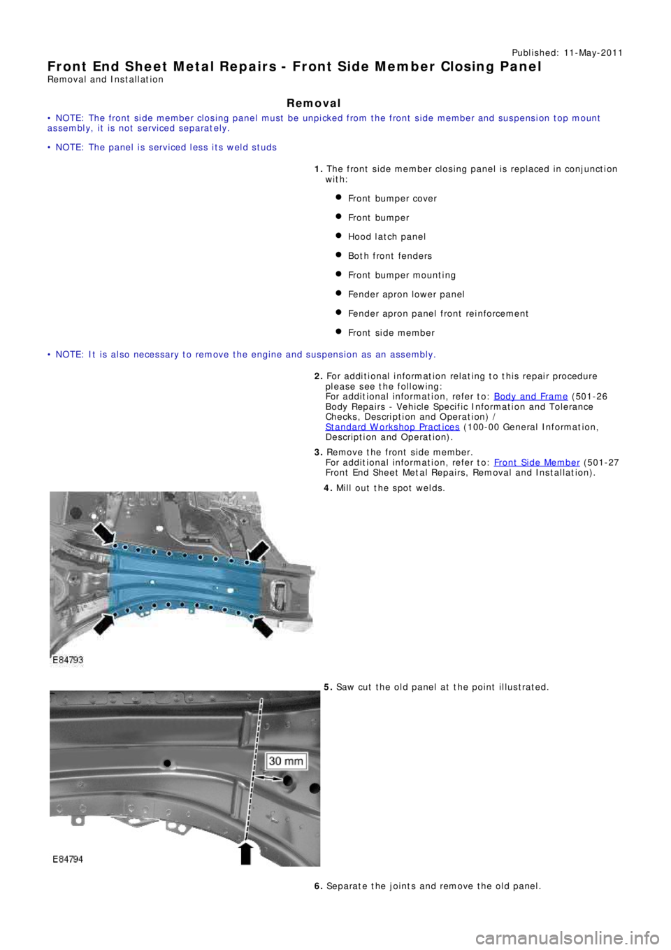
4. Mill out the spot welds.
5. Saw cut the old panel at the point illustrated.
6. Separate the joints and remove the old panel.