2006 LAND ROVER FRELANDER 2 air suspension
[x] Cancel search: air suspensionPage 2634 of 3229
Ite m De scr iption
19 Inner quart er panel and wheelhous e
20 Re a r bumpe r mount i ng
21 Li ft gat e
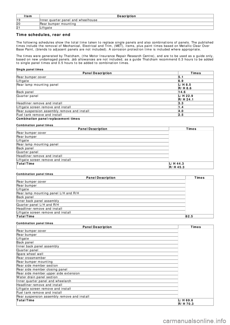
Time schedules, rear end
The following schedules show the total time taken to replace single panels and also combinations of panels. The published
times include the removal of Mechanical, Electrical and Trim, (MET), items, plus paint times based on Metallic Clear Over
Base Paint, (blends to adjacent panels are not included). A corrosion protection time is included where appropriate.
The times were generated by Thatcham, (the Motor Insurance Repair Research Centre), and are to be used as a guide only,
based on new undamaged panels. Job allowances are not included, as a guide Thatcham recommend 0.3 hours to be added
to single panel times and 0.5 hours to be added to combination times.
Single panel timesP a n e l D e s c r ip t io n T ime s
Rear bumper cover5.1
Liftgate6.9
Rear l amp mount ing panelL/H 8.5
R/H 8.6
Back panel14.6
Quarter panelL/H 22.9
R/H 24.1
Headliner remove and install3.3
Liftgate screen remove and install1.4
Rear suspension assembly remove and install4.0
Fuel tank remove and install2.5
C o mb in a t io n p a n e l r e p la c e me n t t ime s
C o mb in atio n p an el times
P a n e l D e s c r ip t io n T ime s
Rear bumper cover
Rear bumper
Liftgate
Rear l amp mount ing panel
Back panel
Quarter panel
Headliner remove and install
Liftgate screen remove and install
Total TimeL/H 44.3
R/H 45.3
C o mb in atio n p an el times
P a n e l D e s c r ip t io n T ime s
Rear bumper cover
Rear bumper
Liftgate
Rear lamp mounting panel L/H and R/H
Back panel
Inner back panel assembly
Quarter panel L/H and R/H
Headliner remove and install
Liftgate screen remove and install
Total Time62.5
C o mb in atio n p an el times
P a n e l D e s c r ip t io n T ime s
Rear bumper cover
Rear bumper
Liftgate
Back panel
Inner back panel assembly
Quarter panel
Spare wheel well
Rear crossmember
Re a r bumpe r mo unt i ng
Re a r s i de me mbe r s e ct i o n
Re a r s i de me mbe r cl os i ng pa ne l
Rear side member upper side extension
W at er drai n panel s ect i on
I nne r q ua rt e r p a ne l a nd whe e l a rch
Headliner remove and install
Liftgate screen remove and install
Fuel tank remove and install
Rear suspension assembly remove and install
Total TimeL/H 69.6
R/H 70.3
Page 2642 of 3229
Publ is hed: 11-May-2011
Rear End Sheet Metal Repairs - Rear Side Member Section
Removal and Installation
Removal
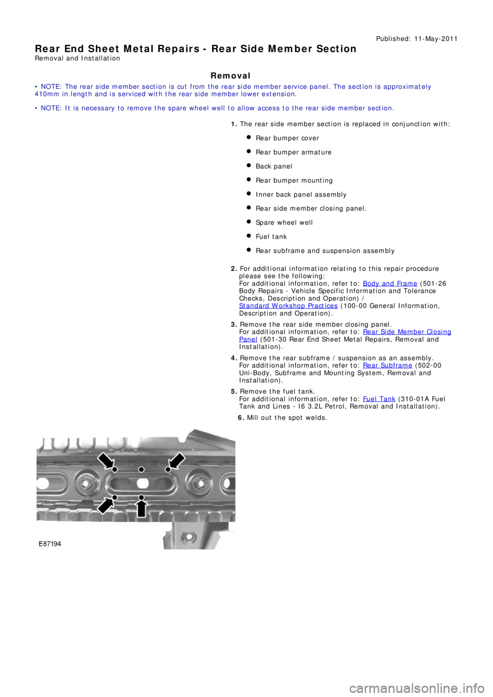
• NOTE: The rear side member section is cut from the rear side member service panel. The section is approximately
410mm in length and is serviced with the rear side member lower extension.
• NOTE: It is necessary to remove the spare wheel well to allow access to the rear side member section.
1. The rear side member section is replaced in conjunction with:
Rear bumper cover
Re a r bumpe r a rma t ure
Back panel
Re a r bumpe r mo unt i ng
Inner back panel assembly
Re a r s i de me mbe r cl os i ng pa ne l .
Spare wheel well
Fuel t ank
Rear subframe and suspension assembly
2. Fo r a d d i t i o na l i nf o rma t i o n re l a t i ng t o t hi s re p a i r p ro ce d ure
please see the following:
Fo r a d d i t i o na l i nf o rma t i o n, re f e r t o : Body and Frame
(501-26
Body Repairs - Vehicle Specific Information and Tolerance
Checks, Description and Operation) /
St a nd a rd W o rks ho p P ra ct i ce s
(100-00 Ge ne ra l I nf o rma t i o n,
Description and Operation).
3. Re move t he re a r s i de me mbe r cl os i ng pa ne l .
Fo r a d d i t i o na l i nf o rma t i o n, re f e r t o : Rear Side Member Closing
Panel (501-30 Rear End Sheet Metal Repairs, Removal and
Installation).
4. Remove the rear subframe / suspension as an assembly.
Fo r a d d i t i o na l i nf o rma t i o n, re f e r t o : Rear Subframe
(502-00
Uni-Body, Subframe and Mounting System, Removal and
Installation).
5. Remove the fuel tank.
Fo r a d d i t i o na l i nf o rma t i o n, re f e r t o : Fuel Tank
(310-01A Fuel
Tank and Lines - I6 3.2L Petrol, Removal and Installation).
6. Mill out the spot welds.
Page 2646 of 3229
Publ is hed: 11-May-2011
Rear End Sheet Metal Repairs - Rear Side Member Closing Panel
Removal and Installation
Removal
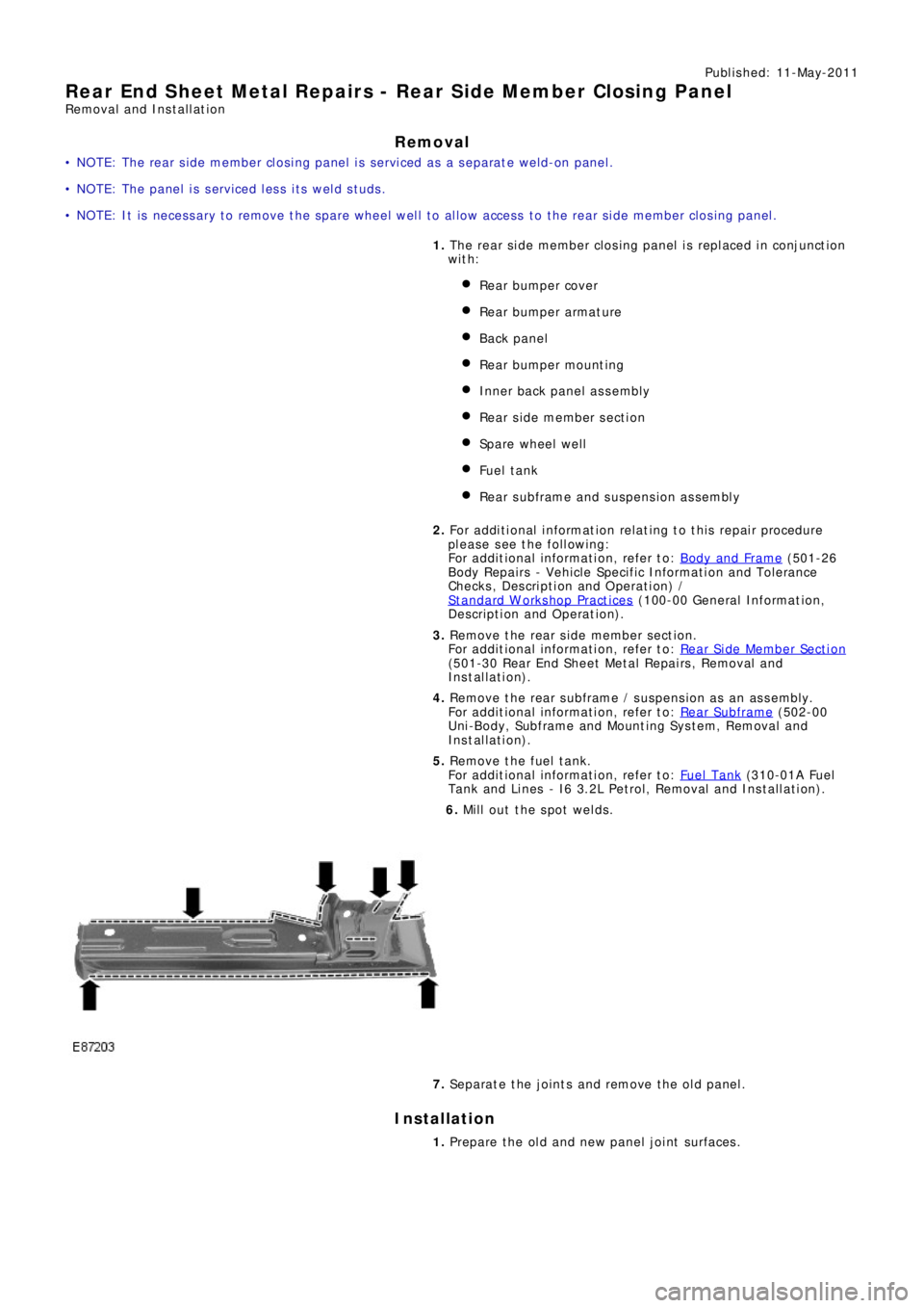
• NOTE: The rear side member closing panel is serviced as a separate weld-on panel.
• NOTE: The panel is serviced less its weld studs.
• NOTE: It is necessary to remove the spare wheel well to allow access to the rear side member closing panel.
1. The rear side member closing panel is replaced in conjunction
with:
Rear bumper cover
Re a r bumpe r a rma t ure
Back panel
Re a r bumpe r mo unt i ng
Inner back panel assembly
Re a r s i de me mbe r s e ct i o n
Spare wheel well
Fuel t ank
Rear subframe and suspension assembly
2. Fo r a d d i t i o na l i nf o rma t i o n re l a t i ng t o t hi s re p a i r p ro ce d ure
please see the following:
Fo r a d d i t i o na l i nf o rma t i o n, re f e r t o : Body and Frame
(501-26
Body Repairs - Vehicle Specific Information and Tolerance
Checks, Description and Operation) /
St a nd a rd W o rks ho p P ra ct i ce s
(100-00 Ge ne ra l I nf o rma t i o n,
Description and Operation).
3. Re move t he re a r s i de me mbe r s e ct i on.
Fo r a d d i t i o na l i nf o rma t i o n, re f e r t o : R e a r Si d e Me mb e r Se ct i o n
(501-30 Rear End Sheet Metal Repairs, Removal and
Installation).
4. Remove the rear subframe / suspension as an assembly.
Fo r a d d i t i o na l i nf o rma t i o n, re f e r t o : Rear Subframe
(502-00
Uni-Body, Subframe and Mounting System, Removal and
Installation).
5. Remove the fuel tank.
Fo r a d d i t i o na l i nf o rma t i o n, re f e r t o : Fuel Tank
(310-01A Fuel
Tank and Lines - I6 3.2L Petrol, Removal and Installation).
6. Mill out the spot welds.
7. Separate the joints and remove the old panel.
Installation
1. Prepare the old and new panel joint surfaces.
Page 2649 of 3229
Publ is hed: 11-May-2011
Rear End Sheet Metal Repairs - Spare Wheel Well
Removal and Installation
Removal
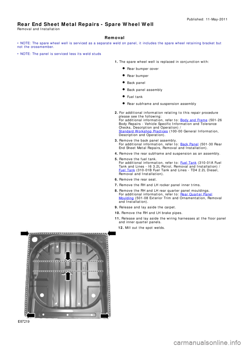
• NOTE: The spare wheel well is serviced as a separate weld on panel, it includes the spare wheel retaining bracket but
not the crossmember.
• NOTE: The panel is serviced less its weld studs
1. The spare wheel well is replaced in conjunction with:
Rear bumper cover
Rear bumper
Back panel
Back panel assembly
Fuel t ank
Rear subframe and suspension assembly
2. Fo r a d d i t i o na l i nf o rma t i o n re l a t i ng t o t hi s re p a i r p ro ce d ure
please see the following:
Fo r a d d i t i o na l i nf o rma t i o n, re f e r t o : Body and Frame
(501-26
Body Repairs - Vehicle Specific Information and Tolerance
Checks, Description and Operation) /
St a nd a rd W o rks ho p P ra ct i ce s
(100-00 Ge ne ra l I nf o rma t i o n,
Description and Operation).
3. Remove the back panel assembly.
Fo r a d d i t i o na l i nf o rma t i o n, re f e r t o : Back Panel
(501-30 Rear
End Sheet Metal Repairs, Removal and Installation).
4. Remove the rear subframe and suspension as an assembly.
5. Remove the fuel tank.
Fo r a d d i t i o na l i nf o rma t i o n, re f e r t o : Fuel Tank
(310-01A Fuel
Tank and Lines - I6 3.2L Petrol, Removal and Installation) /
Fuel Tank
(310-01B Fuel Tank and Li nes - TD4 2.2L Di es el,
Removal and Installation).
6. Remove the rear seat.
7. Remove the RH and LH rocker panel inner trims.
8. Remove the RH and LH rear quarter panel mouldings.
Fo r a d d i t i o na l i nf o rma t i o n, re f e r t o : Rear Quarter Panel
Moulding (501-08 Ext eri or Trim and Ornament at i on, Removal
and Installation).
9. Release and lay aside the carpet.
10. Remove the RH and LH brake pipes.
11. Release and lay aside the wiring harnesses at the floor panel
and inner quarter panels.
12. Mill out the spot welds.
Page 2685 of 3229
Publ is hed: 11-May-2011
Rear End Sheet Metal Repairs - Inner Quarter Panel and Wheelhouse
Removal and Installation
Removal
• NOTE: The inner quarter panel and wheelhouse is an assembly of the inner quarter panel, rear wheelhouse inner, rear
wheelhous e out er and t he rear lamp mount ing panel.
• NOTE: The service panel is not fully welded.
• NOTE: The panel is sectioned to avoid disturbing the roof panel.
1. The inner quarter panel and wheelhouse is replaced in
conjunct ion wit h:
Rear bumper cover
Rear bumper
Quarter panel
Rear door
Quarter glass
Rear subframe and suspension assembly
2. Fo r a d d i t i o na l i nf o rma t i o n re l a t i ng t o t hi s re p a i r p ro ce d ure
please see the following:
Fo r a d d i t i o na l i nf o rma t i o n, re f e r t o : Body and Frame
(501-26
Body Repairs - Vehicle Specific Information and Tolerance
Checks, Description and Operation) /
St a nd a rd W o rks ho p P ra ct i ce s
(100-00 Ge ne ra l I nf o rma t i o n,
Description and Operation).
3. Remove the quarter panel.
Fo r a d d i t i o na l i nf o rma t i o n, re f e r t o : Quarter Panel
(501-30
Rear End Sheet Metal Repairs, Removal and Installation).
4. Remove the rear subframe / suspension as an assembly.
5. Remove the brake pipe.
6. RH Only: Release and lay aside the fuel vent hose.
7. Remove the rear seat backrest.
Fo r a d d i t i o na l i nf o rma t i o n, re f e r t o : Front Seat Backres t Heat er
Ma t (501-10 Seating, Removal and Installation).
8. Release and lay aside the wiring harness.
Page 2757 of 3229
37
Introduction
R
DATA RECORDING
Service data recording
Service data recorders in your vehicle are
capable of collecting and storing diagnostic
information about your vehicle. This potentially
includes information about the performance or
status of various syst ems and modules in the
vehicle such as engine, throttle, steering or
brakes.
In order to properly di agnose and service your
vehicle, Land Rover a nd service and repair
facilities may access vehicle diagnostic
information through a direct connection to
your vehicle.
Event data recording
Event data recorders are capable of collecting
and storing data during a crash or near-crash
event. The recorded information may assist in
the investigation of such an event. The
modules may record information about both
the vehicle and the oc cupants, potentially
including information such as:
• How various systems in your vehicle were
operating.
• Whether or not the driver and passenger
seat belts were buckled.
• How far, if at all, the driver was depressing
the accelerator and/or the brake pedal.
• How fast the vehicle was travelling.
• Where the driver was positioning the
steering wheel.
To access this information special equipment
must be connected directly to the recording
modules. Land Rover do not access event data
recorder information without obtaining
consent, unless pursuan t to court order or
where required by law enforcement, other
government authorities or third parties acting
with lawful authority. Other parties may seek to access the
information independe ntly of Land Rover.
DISABILITY MODIFICATIONS
Occupants with disabili ties which may require
modification of the vehi cle must contact a Land
Rover Dealer/Authorised Repairer before any
modifications are made.
PARTS AND ACCESSORIES
WARNINGS
The fitting of non-approved parts and
accessories, or the carrying out of
non-approved alterations or
conversions, may be dangerous and could
affect the safety of th e vehicle and occupants
and also invalidate the terms and conditions of
the vehicle warranty.
Land Rover will not accept any liability
for death, personal injury or damage to
property which may occur as a direct
result of fitment of non-approved accessories
or the carrying out of non-approved
conversions to La nd Rover vehicles.
Land Rover strongly advise against
making any modifications to the
suspension or steering system. This
could seriously affe ct the handling and
stability of the vehicle leading to loss of control
or roll-over.
Page 2925 of 3229
205
Status after a collision
R
Status after a collisionDRIVING AFTER A COLLISION
Before starting or driving
If the vehicle has been involved in an accident
it should be checke d thoroughly before
attempting to start the engine or drive the
vehicle.
Check for :-
• Fuel leaks.
• Fluid leaks.
• Battery damage.
• Damage to wiring.
• Damage to lights.
• Damage to steering, suspension, wheels
or tyres.
• Sharp or protruding bodywork.
• Operation of doors and locks.
• Condition and operation of seat belts and
SRS components.
• Condition of chil d seats and their
mounting/attach ment points.
Note: This list is not exhaustive.
Resetting the fuel cut-off
The fuel system cut-off forms part of the Safety
and Restraint System (SRS) fitted to your
vehicle. Following an im pact, and depending on
the severity, the fuel pump may be switched
off.
1. Switch the ignition off, and wait for one
minute.
2. Turn the ignition on for 30 seconds.
3. Check the vehicle thoroughly for fuel leaks.
If a leak is detected switch the ignition off
immediately.
• The vehicle must not be started if a leak
is present. Seek qualified advice, and
have the vehicle recovered.
4. If no leaks are detected, start the vehicle.
When driving
When driving a vehicle which has been
involved in a collision use caution and pay extra
attention to the operation of the vehicle. If any
changes in vehicle operati on after the collision
are noted when compared to it's operation
before the collision, do not continue to drive
the vehicle. Stop the vehicle as soon as it is
safe to do so, and have the vehicle recovered.
Pay particular attent ion to changes in :-
• Steering.
• Braking.
• Unusual noises.
• Warning lights or messages displayed.
• Problems with electrical systems.
WARNING
If the vehicle is involved in a collision it
should be checked by a Land Rover
Dealer/Authorised repairer, or suitably
qualified persons before starting or driving.
WARNING
The fuel cut-off s hould never be reset
if you can smell fuel , or a leak can be
seen. Doing so can lead to a fire which
may cause personal injury or death.