2006 LAND ROVER FRELANDER 2 fuse box diagram
[x] Cancel search: fuse box diagramPage 1830 of 3229

• NOTE: The fus i bl e l inks are mount ed on t he inboard s i de of the BJB behind a series of removable covers .
The CJB is mount ed behind t he glovebox and recei ves it s main power s uppl y from the BJB. In addi ti on to cont aining bl adefus es , the CJB i s t he main controll er for a number of vehicle s ys t ems. Thes e functi ons are out li ned in t he rel evant s ect ionsof thi s manual .
The AJB is locat ed beneat h t he luggage compartment carpet , adjacent t he spare wheel wel l. The AJB i s a modular des ign,and compris es up t o 3 individual elements depending on vehicle specificati on. The AJB cont ains bl ade and J-cas e fuses ,and rel ays to di st ribute el ect ri cal power to sys t ems used at the rear of t he vehi cle. The AJB receives it s mai n power s upplyfrom the BJB.
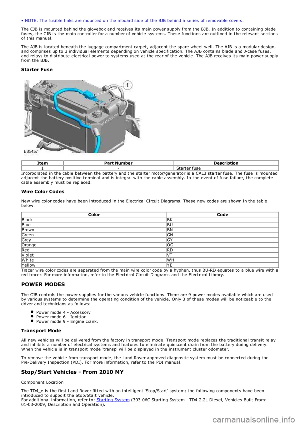
Starter Fuse
ItemPart NumberDescription
1-Starter fus e
Incorporat ed i n the cable bet ween t he bat t ery and t he s tarter mot or/generat or is a CAL3 st art er fus e. The fus e is mount edadjacent t he batt ery pos it ive t erminal and is i ntegral wi th t he cable as s embly. In the event of fus e fai lure, t he completecabl e as sembl y mus t be repl aced.
Wire Color Codes
New wi re col or codes have been i ntroduced i n the El ect ri cal Ci rcuit Di agrams . Thes e new codes are s hown i n t he tablebelow.
ColorCode
BlackBK
BlueBUBrownBN
GreenGN
GreyGYOrangeOG
RedRD
Viol etVTW hi teW H
Y ell owY E
Tracer wire col or codes are s eparat ed from the main wi re col or code by a hyphen, t hus BU-RD equat es to a blue wire wit h ared tracer. For more informat ion, refer to t he Elect rical Circui t Diagrams and the El ect ri cal Library.
POWER MODES
The CJB cont rol s the power s uppl ies for the vari ous vehi cl e functi ons. There are 9 power modes availabl e which are usedby vari ous s ys tems to det ermi ne t he operati ng condit ion of t he vehi cle. Only 3 of thes e modes wil l be noti ceable t o t hedri ver and t echnici ans as foll ows:
Power mode 4 - Acces s oryPower mode 6 - Igni ti onPower mode 9 - Engine crank.
Transport Mode
All new vehicles will be del ivered from the factory in t rans port mode. Trans port mode repl aces t he t radit ional trans i t relayand inhibi ts a number of el ect ri cal s ys t ems and feat ures t o eli mi nat e quies cent drain from the bat tery during del ivery.W hen t he vehicle i s in transport mode 't rans p' wi ll be di spl ayed i n t he ins trument cl ust er odomet er.
To remove the vehicle from t rans port mode, the Land Rover approved di agnos ti c s ys t em mus t be connect ed during t hePre-Delivery Ins pect ion (PDI). For more i nformati on, refer t o the PDI manual .
Stop/Start Vehicles - From 2010 MY
Component Locat ion
The TD4_e is t he first Land Rover fit t ed wit h an i ntell igent ‘St op/Start’ s yst em; t he fol lowing component s have beenint roduced to support t he Stop/St art vehicle.For addit ional informat ion, refer t o: Starti ng Sys t em (303-06C Starti ng Syst em - TD4 2.2L Di es el, Vehicles Bui lt From:01-03-2009, Descripti on and Operat ion).
Page 2374 of 3229

1
2
1
1
2
1
1
1
Is t he fused li nk (VBAT T ) circuit t o t he roof opening panel mot orinta ct ?YesGO to C2.NoThe fused link t o t he roof ope ning panel mot or has failed.Refer t o the e lect rical circuit diagrams and check the(VBAT T) circuit bet wee n t he fuse d l ink and t he roof openingpanel mot or for short ci rcuit t o ground. Replace the fus ed linkor repair t he circuit a s required. Check for correct roofopening panel ope rat ion.C2: VEHICLE - AUT HORIZAT ION• NOTE: W it h the igniti on st ate ON t he authorizat ion signal voltage is supplied on t he (ACC) circuit of t he roof opening panel mot or, ands hould be great er than 7volts when t he roof pa nel aut horizat ion signal is active and l ess t han 1volt when t he roof panel aut horizat ion signa lis inactive.Acces s t he roof opening panel swit ch.REFER to: Overhead Console (501-12 Inst rument P anel andConsole, Removal and Inst allat ion).Refer t o the e lect rical circuit diagrams and check the (ACC)circuit t o the roof openi ng panel mot or for corre ct operation(se e note above).Doe s the (ACC) circuit t o t he roof opening panel motor show theexpected volta ges?YesGO to C3.NoConfirm DT C B10F2-14 (Sunroof cont rol - circuit short toground or open) ha s been st ored, refer t o t he elect rical circuitdiagrams and check t he (ACC) circuit bet ween the cent raljunct ion box and t he roof opening pane l motor for fault .Repair a s required.If t he DTC ha s not been st ored,invest igat e the cent ral junct ion box (ACC) circuit operat ion.C3: ROOF OPENING PANEL - SWITCH CONNECT ORRefer t o the e lect rical circuit diagrams and check the roofopening panel s wit ch t erminals and housing for locat ion andcondit ion.Are t he roof opening panel swit ch t erminal s and housing locat edcorrectly and i n good condi tion?YesGO to C4.NoCorrectly re locat e or replace any roof opening panel swit chconnector t erminals a s required. Check for correct roofopening panel ope rat ion.C4: ROOF OPENING PANEL - MOT OR CONNECT ORAcces s t he roof opening panel mot or.REFER to: Roof Opening Panel Mot or (501-17 Roof OpeningPanel, Removal and Inst allat ion).Refer t o the e lect rical circuit diagrams and check the roofopening panel mot or t erminals and housing for locat ion andcondit ion.Are t he roof opening panel motor connector t erminals and housinglocat ed correct ly and in good condit ion?YesGO to C5.NoCorrectly re locat e or replace any roof opening panel mot orconnector t erminals a s required. Check for correct roofopening panel ope rat ion.C5: SWIT CH - CIRCUIT CHECK 1• NOTE: The roof ope ning panel mot or gives a volta ge out on t he open and close circuit s which is grounded when t he swit ch is operat ed, t hisvolta ge should be great er than 7volts (switch inactive) and less t han 1volt (switch active) wit h t he ignit ion st at e s wit ched to on.Refer t o the e lect rical circuit diagrams and locat e the openand close circuits between t he roof opening panel mot or andthe roof opening panel swi tch, monit or t he volt age on eachcircuit as t he switch is operat edDo both open and close swit ch circuit volt ages change fromgreate r t han 7volts t o less t han 1volt when t he roof openingpanel open or close s wit ches are operat ed?YesGO to C8.NoGO to C6.C6: SWIT CH - CIRCUIT CHECK 2• NOTE: During t he previous check, if t he voltage rema ined high (greater than 7volts), refer to t he electrical circuit diagrams and check t hes wit ch circuit for faul t.• NOTE: During t he previous check, if t he voltage rema ined low (less than 1volt), refer t o the e lect rical circuit diagrams and check the roofopening panel mot or circuit for fault .Refer t o not es above .Did t he volt age remai n l ow (less than 1volt)?YesGO to C7.NoThe volt age remained high (above 7volts) refe r t o t heelect rical circuit diagrams and check the roof opening panelswit ch circuit for fa ult.C7: MOT OR SUPPLY - VOLT AGERefer t o the e lect rical circuit diagrams and check the volta gebetween t he powe r (VBATT ) and ground (GND) circuit s t othe roof opening panel mot or for bat t ery supply volta ge(approx. 12volts).